
Subscribe to Our Youtube Channel
Related Manuals for RGB Technology ZB20


Summary of Contents for RGB Technology ZB20
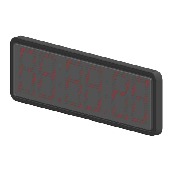
- Page 1 TECHNICAL DOCUMENTATION ZB20 CLOCKS in the Prestige line casing Catalogue index no: 301-09-XX * Explanatory figure...
-
Page 2: Table Of Contents
Table of contents Specifications ..................................3 Transport and storage ................................ 3 Device construction ................................3 Construction of the ZB20 clocks ..........................4 3.1.1 List of display cables ............................4 Dimensions of the ZB20 device ..........................4 3.2.1 Mounting the ZB20 device ..........................4 Installation of the device .............................. -
Page 3: Specifications
99%RH. 3 Device construction ZB20 has a housing made of polycarbonate, which is resistant to UV radiation and has a high mechanical strength. By using the thermo-moulded housing and a rear sealing layer, the device, when properly assembled, meets the IP66 tightness requirements. -
Page 4: Construction Of The Zb20 Clocks
3.1 Construction of the ZB20 clocks Front view Back view det. A – extender box; det. B – M5x10 screw; det. C – technological hole plug; det. D – mounting bracket; det. E – power supply unit; det. F – Prestige Line casing;... -
Page 5: Installation Of The Device
NOTICE! It is forbidden to make any additional mounting points or any holes in the device assembly components. 4.1 ZB20 devices The ZA20 devices are designed to display time, date, and optionally temperature. For the proper operation of the device, it should be correctly configured. As a standard the device is configured using LAN. -
Page 6: Compact-Clock Extender Module
5 Compact-clock extender module The extender module (Fig. 4) enables the operation of peripheral devices and, thanks to a battery, ensures correct time counting when there is no external power supply. det. A signal LEDS; det. B – relay; det. C –... -
Page 7: Additional Options
8 Additional options 8.1 IR remote control unit IR remote control unit (Fig. 5), catalogue index number 300-03-09, enables entering the embedded user menu. You can do it by pressing the „MENU” button (Fig.5, det. C) Fig. 5 det. A –...
Need help?
Do you have a question about the ZB20 and is the answer not in the manual?
Questions and answers