
Related Manuals for GEZE E 212 R


Summary of Contents for GEZE E 212 R
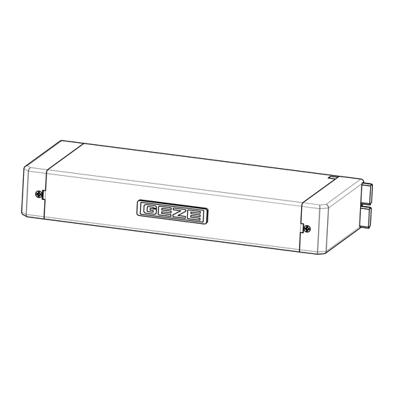
- Page 1 E 212 R1 /230 V AC DE Anschlussplan GB Wiring diagram E 212 R /230 V AC E 212 /24 V DC DE Linearantrieb GB Linear drive...
-
Page 2: Table Of Contents
E 212 R1 / E 212 R / E 212 Inhaltsverzeichnis Symbole und Darstellungsmittel ............3 Sicherheitshinweise ................3 Produkthaftung........................3 Allgemeine Sicherheitshinweise..................4 Montagehinweise ......................4 Leitungsverlegung und elektrischer Anschluss .............5 Sicherheitsbewusstes Arbeiten und Benutzen ............5 Prüfen der montierten Anlage ..................6 Entsorgung der Fensteranlage ............6 Wartung .....................6... -
Page 3: Symbole Und Darstellungsmittel
E 212 R1 / E 212 R / E 212 Symbole und Darstellungsmittel Symbole und Darstellungsmittel Warnhinweise In dieser Anleitung werden Warnhinweise verwendet, um Sie vor Sach- und Personenschäden zu warnen. Lesen und beachten Sie diese Warnhinweise immer. Befolgen Sie alle Maßnahmen, die mit dem Warnsymbol und Warnwort gekennzeichnet sind. -
Page 4: Allgemeine Sicherheitshinweise
Sicherheitshinweise E 212 R1 / E 212 R / E 212 tageanleitungen des Produkts enthaltenen Informationen (Produktin- formationen und bestimmungsgemäße Verwendung, Fehlgebrauch, Produktleistung, Produktwartung, Informations- und Instruktionspflich- ten) zu beachten. Die Nichtbeachtung entbindet den Hersteller von seiner Haftungspflicht. à Nur Sachkundige, die von GEZE autorisiert sind, dürfen Montage, Funk- tionsprüfung und Wartung durchführen. -
Page 5: Leitungsverlegung Und Elektrischer Anschluss
E 212 R1 / E 212 R / E 212 Sicherheitshinweise Lesen und beachten Sie die Angaben in der Montageanleitung und be- wahren Sie diese für den späteren Gebrauch auf. Alle Maßangaben sind am Bau eigenverantwortlich zu prüfen. à Der Antrieb ist ausschließlich für den Einsatz in trockenen Räumen bestimmt und darf keiner stark korrosionsgefährdenden Umgebung... -
Page 6: Sicherheitsbewusstes Arbeiten Und Benutzen
Sicherheitshinweise E 212 R1 / E 212 R / E 212 Bei den Anschlüssen von Komponenten müssen die Angaben in dieser Beschreibung beachtet werden. Die Planung und Berechnung des Leis- tungsnetzes obliegt dem sachkundigen Errichter und muss entsprechend der gesetzlichen Vorschriften durchgeführt werden (in Deutschland z. B. -
Page 7: Entsorgung Der Fensteranlage
E 212 R1 / E 212 R / E 212 Entsorgung der Fensteranlage Nach der Installation ist zu überprüfen, dass die Anlage richtig eingestellt ist und richtig und gefahrlos funktioniert. Alle Funktionen durch Probelauf überprüfen. à Der Endanwender muss nach der Fertigstellung in allen wichtigen Be- dienschritten eingewiesen werden. -
Page 8: Elektrischer Anschluss
Elektrischer Anschluss E 212 R1 / E 212 R / E 212 Elektrischer Anschluss Gefahr durch elektrischen Strom! GEFAHR! Beim Anschluss des Antriebs sicherstellen, dass keine Netzspannung an den Anschlussklemmen anliegt! E 212 R1 /230 V E 212 R /230 V E 212 /24 V Kabelführungsöffnung aus-... -
Page 9: Technische Daten
E 212 R1 / E 212 R / E 212 Technische Daten Technische Daten Hauptmaße Mechanische Daten E212 R1 230 V / E 212 /24 V DC E 212 R 230 V AC max. Zug- und Druckkraft [N] 1500 1500... -
Page 10: Hub-/Endlageeinstellung
Hub-/Endlageeinstellung E 212 R1 / E 212 R / E 212 Hub-/Endlageeinstellung LED (grün) Einstellschraube Hub Der Hub ist ab Werk auf 52 mm eingestellt. Hub entsprechend Beschlaghub einstellen und prüfen. Einstellwert = Beschlaghub -2 mm. Beispiel OL90: Beschlaghub 54 mm = Einstellwert Antrieb 52 mm. - Page 11 E 212 R1 / E 212 R / E 212 DE 11...
- Page 12 E 212 R1 / E 212 R / E 212 Contents Symbols and means of representation ...........3 Safety instructions ..................3 Product liability ........................3 General safety precautions ....................4 Installation notes .......................4 Routing cables and electrical connection ..............5 Safety-conscious working and usage ................6 Inspection of installed system ..................6...
-
Page 13: Symbols And Means Of Representation
E 212 R1 / E 212 R / E 212 Symbols and means of representation Symbols and means of representation Warnings In these instructions, warnings are used to warn against material damage and injuries. Always read and observe these warnings. -
Page 14: General Safety Precautions
à GEZE shall not be liable if devices from other manufacturers are used with GEZE equipment. Use only original GEZE parts for repair and main- tenance work as well. -
Page 15: Routing Cables And Electrical Connection
E 212 R1 / E 212 R / E 212 Safety instructions Read and observe the specifications in the mounting instructions and keep these for later use. All the dimensions specified have to be checked on site on own initiative and responsibility. -
Page 16: Safety-Conscious Working And Usage
OFF default setting must be used (e.g. GEZE Mat. No. 117996 for SCT, 090176 for cylinder). The switch has to be mounted so that the points of danger can be seen. -
Page 17: Disposal Of The Window Unit
Dispose of the parts in accordance with the statutory regulations. Maintenance GEZE prescribes regular maintenance (at least once a year). This is to be carried out by a suitably qualified person. In the process the operation as well as the condition of the mechanical equipment (imbalance or signs of wear, damage to fastening parts) and the electrical connections are to be checked. -
Page 18: Electrical Connection
Electrical connection E 212 R1 / E 212 R / E 212 Electrical connection Danger of electric shock! DANGER! When connecting the drive, make sure there is no mains voltage at the supply terminals! E 212 R1 /230 V E 212 R /230 V... -
Page 19: Technical Data
E 212 R1 / E 212 R / E 212 Technical data Technical data Main dimensions Mechanical data E212 R1 230 V / E 212 /24 V DC E 212 R 230 V AC Max. tensile force and force of pressure [N] 1500... -
Page 20: Stroke/End Position Setting
Stroke/end position setting E 212 R1 / E 212 R / E 212 Stroke/end position setting LED (green) Setting screw stroke The stroke is set to 52 mm in the factory. Set and check the stroke according to fitting stroke Setting value = Fitting stroke – 2 mm... - Page 21 E 212 R1 4 x 1,5 mm LTA-LSA (ID: 118476) 3 x 1,5 mm 230 V AC 230 V AC 230 V AC GN/YE...
- Page 22 E 212 R 5 x 1,5 mm LTA-230 (ID: 118474) 5 x 1,5 mm 3 x 1,5 mm 230 V AC 230 V AC 230 V AC 230 V AC 230 V AC GN/YE A-II...
- Page 23 E 212 3 x 1,5 mm 24 V DC 24 V DC 24 V DC A-III...
- Page 26 Notizen/Notes E 212 R1 / E 212 R / E 212...
- Page 27 Notizen/Notes E 212 R1 / E 212 R / E 212...
- Page 28 Tel. +49 (0) 7930-9294-0 Baltic States India Singapore Fax +49 (0) 7930-9294-10 GEZE GmbH Baltic States office GEZE India Private Ltd. GEZE (Asia Pacific) Pte, Ltd. E-Mail: sk.de@geze.com E-Mail: office-latvia@geze.com E-Mail: office-india@geze.com E-Mail: gezesea@geze.com.sg GEZE GmbH www.geze.com www.geze.in...
Need help?
Do you have a question about the E 212 R and is the answer not in the manual?
Questions and answers