
Related Manuals for Matrix Orbital GTT480272A


Summary of Contents for Matrix Orbital GTT480272A
- Page 1 GTT480272A Hardware Manual Revision 1.5 PCB Revision: 1.4 or Higher Firmware Revision: 1.0 or Higher...
- Page 2 Revision History Revision Date Description Author August 21 , 2012 Updated I2C Section Clark March 10 , 2011 Restricted Temperature Rating Clark August 24 , 2010 Additional Heading Numbers and Additional Formatting Clark July 28 , 2010 Added Defect Criteria Clark July 22 , 2010...
-
Page 3: Table Of Contents
Contents Introduction ............................1 Quick Connect Guide ..........................2 Available Headers ......................... 2 Standard Module .......................... 3 2.2.1 Recommended Parts ......................3 2.2.2 Serial Connections ......................... 3 I2C Module ............................ 4 2.3.1 Recommended Parts ......................4 2.3.2 C Connections ........................4 USB Module .......................... - Page 4 4.5.1 Mass Storage Mini USB Connector ..................11 4.5.2 SD Memory Card ......................... 11 4.5.3 Mass Storage Mode ......................11 4.5.4 Field Upgrade ........................11 Troubleshooting ..........................12 Power ............................12 Display ............................12 Communication ........................... 12 Factory Defaults .......................... 13 Appendix .............................
-
Page 5: Introduction
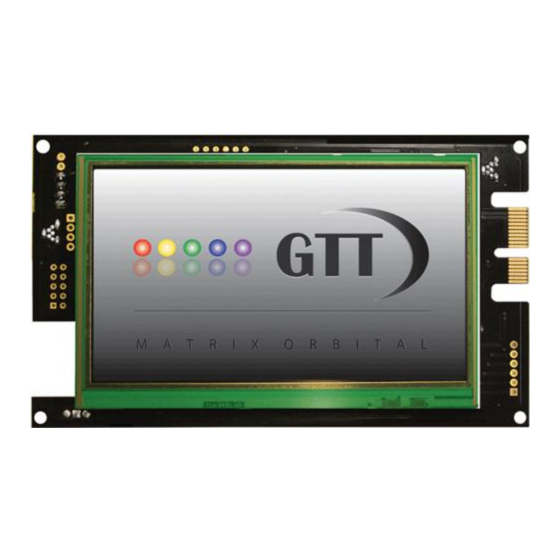
1 Introduction Figure 1: GTT480272A Display The Matrix Orbital GTT480272A is a full colour TFT display with an integrated touch screen crafted to become a crisp, controllable canvas for creativity. Utilizing an extended version of our widely used command protocol and industry standard communication protocols, the customizable GTT480272A will quickly become the gorgeous face of your application. -
Page 6: Quick Connect Guide
2 Quick Connect Guide 2.1 Available Headers Figure 2: GTT480272A Header Locations Table 1: List of Available Headers Header Mate Population Extended Communication/Power ESCCPC5V Standard Model Only Standard Communication/Power I2C Model Only USB Communications EXTMUSB3FT/ INTMUSB3FT USB/I2C Models Only Alternate USB... -
Page 7: Standard Module
2.2 Standard Module The standard version of the GTT480272A allows for user configuration of two common communication protocols. The unit can communicate using flow controlled serial protocol at either RS323 or TTL voltage levels. Connections for each are accessed through the communication/power header as in Table 2. -
Page 8: I2C Module
2.3 I2C Module The I2C version of the GTT480272A offers both a standard 4 pin I2C connection as well as a USB header for debugging purposes without the need to muck about with hardware changes. A simple I2C.cfg file in the SYSTEM folder will tell the unit to respond on the I2C bus, with it missing it will respond via USB. -
Page 9: Usb Module
2.4 USB Module The GTT480272A-USB offers a single USB interface for easy connection to a host computer. This simple but common protocol can be accessed using the on board mini B style USB connector as outlined below. 2.4.1 Recommended Parts The External Mini USB Cable is recommended for the GTT480272A-USB display. -
Page 10: Rs422 Module
2.5.1 RS422 Connections To interface to the robust GTT480272A-422, a series of six wires are usually screwed into the RS422 terminal block provided. This setup will supply power to your display and provide a simple communication scheme. To connect in RS422 mode, adhere to the steps below. -
Page 11: Software
A number of control characters are also activated. Advanced commands are merely values prefixed with a special command byte, 254 in decimal. While many software programs are available to communicate with the GTT480272A, a number of more common samples are detailed in depth below. Table 21: Reserved Control Characters... -
Page 12: Hardware
The Extended Communication/Power Header provides a standard connector for interfacing to the GTT480272A. Voltage is applied through pins one and four of the header. Please ensure the correct voltage input for your display by referencing the electrical specifications in Table 11 before applying power. -
Page 13: I2C Model
The GTT480272A-I2C also comes with a Mini-B USB connector for development and debugging purposes. By removing the I2C.cfg file from the SYSTEM directory, the GTT480272A-I2C can be interfaced to a PC through a standard USB cable. This connection creates a virtual com port that offers a... -
Page 14: Usb Model
Tx (A) Figure 13: RS422 Header The six pin RS422 Header of the GTT480272A-422 offers power and ground connections as well as two differential pair communication lines. Both a regular and an inverted line are provided for both receive and transmit signals. The Tyco 282834-6 style header is best suited to a wire connection. -
Page 15: Common Features
Figure 14: Mass Storage USB Connector The GTT480272A comes with a secondary Mini USB connector to access the SD memory card as a mass storage device for easier access to the files contained on the card. The mass storage jumper must be placed to use this function, please refer to the Mass Storage Mode section for further information. -
Page 16: Troubleshooting
5 Troubleshooting 5.1 Power In order for your Matrix Orbital display to function correctly, it must be supplied with the appropriate power. If the power LED near the top right corner of the board is not illuminated, power is not applied correctly. -
Page 17: Factory Defaults
5.4 Factory Defaults If the settings of your display become altered in a way that dramatically impacts usability, the default settings can be temporarily restored simply by removing the AUTOEXEC file in the memory card’s root directory. This will reset the baud rate to 115,200. -
Page 18: Appendix
- 265 - mA Full Brightness Controller (I C, TTL) ±2 kV Human Body Model 6.6 Electrical Characteristics 6.6.1 Absolute Maximum Ratings Table 14: GTT480272A Limiting Values Parameter Unit Remarks -0.5 Standard Voltage Option Supply Voltage -0.5 Extended Wide Voltage (-VPT) Option... -
Page 19: Communication Characteristics
6.6.2 Communication Characteristics Table 15: RS232 Interface Characteristics Table 16: USB Interface Characteristics Parameter Min Typ Max Unit Parameter Min Typ Max Unit Input Threshold Low 0.6 1.2 Static Out ut High Input Threshold High Static Output Low Input Differential Thre hold Output Voltage Swing ±5.0 ±5.4 Input Resistance... -
Page 20: Dimensional Drawing
6.8 Dimensional Drawing Figure 15: GTT480272A Dimensional Drawing... -
Page 21: Ordering
7 Ordering 7.1 Part Numbering Scheme Table 22: Part Numbering Scheme GTT 480272 A -USB 7.2 Options Table 23: Display Options Designator Options Product Type GTT: TFT Display with Touchscreen Input Display Size 480272: 480 pixel columns by 272 rows Display Form Factor A: A form factor Voltage... -
Page 22: Definitions
Definitions 9-Slice: Graphic format used to scale bitmaps, usually rectangular, without distorting their geometry. Nine regions define the object center, four corners, and four sides for accurate up or down scaling. ASCII: American standard code for information interchange used to give standardized numeric codes to alphanumeric characters. - Page 23 Mouser Electronics Authorized Distributor Click to View Pricing, Inventory, Delivery & Lifecycle Information: Matrix Orbital GTT480272A GTT480272A-USB GTT480272A-VPT GTT480272A-I2C GTT480272A-I2C-VPT...
Need help?
Do you have a question about the GTT480272A and is the answer not in the manual?
Questions and answers