
Related Manuals for Matrix Orbital GLK19264A-7T-1U


Summary of Contents for Matrix Orbital GLK19264A-7T-1U
- Page 1 GLK19264A-7T-1U Including the GLK19264A-7T-1U-USB, and GLK19264A-7T-1U-422 Technical Manual Revision 2.5 PCB Revision: 2.0 or Higher Firmware Revision: 8.4 or Higher...
- Page 2 Revision History Revision Date Description Author October 27, 2015 Correction to Hardware Lock Divino October 19, 2015 Revision to Commands for Firmware Revision 8.6 Clark May 21, 2014 Revision to Commands for Firmware Revision 8.5 Martino March 5, 2014 Correction to Current Draw of Backlights Martino September 9, 2013 Corrected Scripted Key and Keypad Brightness Commands...
-
Page 3: Table Of Contents
Contents 1 Introduction ............................... 1 2 Quick Connect Guide..........................2 2.1 Available Headers ..........................2 2.2 Standard Module ..........................3 Recommended Parts ..........................3 Serial Connections ..........................3 C Connections ............................. 4 2.3 USB Module ............................5 Recommended Parts ..........................5 USB Connections ........................... - Page 4 4.4 Common Features ..........................13 General Purpose Outputs ........................13 Dallas One-Wire Connector ........................ 13 5 Troubleshooting ............................14 5.1 Power ..............................14 5.2 Display ............................... 14 5.3 Communication ..........................15 5.4 Manual Override ..........................15 6 Commands ............................... 16 6.1 Communication ..........................
- Page 5 6.16 Miscellaneous ..........................47 7 Appendix ..............................49 7.1 Command Summary ......................... 49 7.2 Block Diagram ........................... 54 7.3 Environmental Specifications ......................54 7.4 Electrical Tolerances ......................... 54 7.5 Dimensional Drawings ........................55 7.1 Optical Characteristics ........................57 8 Ordering ..............................57 8.1 Part Numbering Scheme ........................
-
Page 6: Introduction
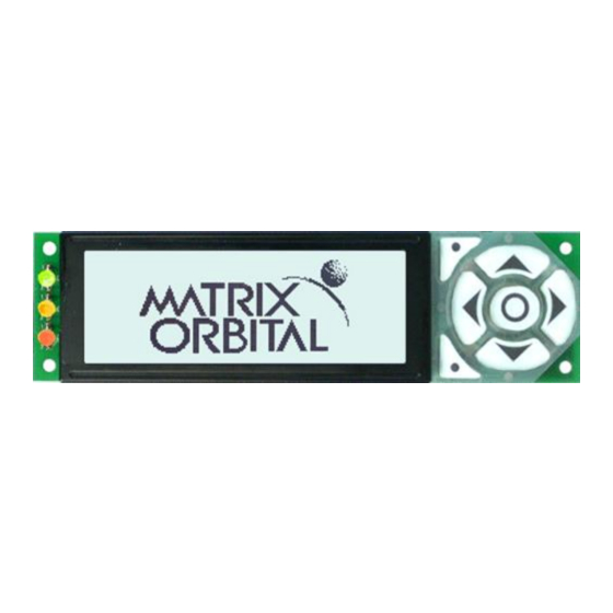
User input on the GLK19264A-7T-1U is available through a built-in seven key tactile keypad. Three bi- colour LEDs provide visual outputs and six general purpose outputs provide simple switchable five volt sources on each model. -
Page 7: Quick Connect Guide
2 Quick Connect Guide 2.1 Available Headers Figure 2: GLK19264A-7T-1U Standard Module Header Locations Figure 3: GLK19264A-7T-1U USB and RS422 Model Header Locations Table 1: List of Available Headers Header Mate Population Mini USB Connector EXTMUSB3FT/INTMUSB3FT USB Model Only RS422 Terminal Block... -
Page 8: Standard Module
2.2 Standard Module The standard version of the GLK19264A-7T-1U allows for user configuration of two common communication protocols. First, the unit can communicate using serial protocol at either RS323 or TTL voltage levels. Second, it can communicate using the Inter-Integrated Circuit connect, or I C protocol. -
Page 9: I 2 C Connections
3. Create. This time you're on your own. While there are many examples within the Matrix Orbital AppNote section, www.matrixorbital.ca/appnotes, too many controllers and languages exist to cover them all. If you get stuck in development, it is possible to switch over to another protocol on the standard board, and fellow developers are always on our forums for additional support. -
Page 10: Usb Module
2.3 USB Module The GLK19264A-7T-1U-USB offers a single USB protocol for easy connection to a host computer. The simple and widely available protocol can be accessed using the on board mini B style USB connector as outlined in the USB Connections section. -
Page 11: Rs422 Module
RS422 terminal block provided. An alternate header is also available to provide local power to a regular or –LV unit. To connect to your GLK19264A-7T-1U-422, adhere to the steps laid out below. -
Page 12: Software
3.1 MOGD# The Matrix Orbital Graphic Display interface, MOGD#, is offered as a free download from www.matrixorbital.ca/software/software_graphic. It provides a simple graphical interface that allows settings, fonts, and bitmaps to be easily customised for any application. -
Page 13: Firmware Upgrade
This program provides both a staging areas for your graphics display and a proving ground that will prepare it for any application environment. 3.2 Firmware Upgrade Beginning with revision 8.1, the firmware of the GLK19264A-7T-1U can be upgraded in the field. All firmware revisions can be installed using software found at www.matrixorbital.ca/software/GLT Series. -
Page 14: Hardware
The Extended Communication/Power Header provides a standard connector for interfacing to the GLK19264A-7T-1U. Voltage is applied through pins one and four of the four pin Communication/Power Header. Please ensure the correct voltage input for your display by referencing Voltage Specifications before connecting power. -
Page 15: Power Through Db9 Jumper
DB-9 Jumper labelled D, as illustrated below. This connection can be made using a zero ohm resistor, recommended size 0603, or a solder bridge. The GLK19264A-7T-1U allows all voltage models to use the power through DB-9 option, see the Voltage Specifications for power requirements. -
Page 16: Usb Model
Alternate USB Header. This header offers power and communication access in a simple interface package. The Optional Alternate USB Header may be added to the GLK19264A-7T-1U-USB for an added charge as part of a custom order. Please use the Contact section to request more information from the friendly Matrix Orbital sales team. -
Page 17: Rs422 Model
Tx (A) Figure 13: RS422 Header The six pin RS422 interface header of the GLK19264A-7T-1U-422 offers power and ground connections as well as two differential pair communication lines. Regular and inverted lines are provided for both receive and transmit signals. Power is supplied locally to the regular or –LV variants while the –VPT can receive power over a distance. -
Page 18: Common Features
Function Figure 16: Dallas One-Wire Connector In addition to the six general purpose outputs the GLK19264A-7T-1U offers an Optional Dallas One-Wire bridge, to allow for an additional thirty two one-wire devices to be connected to the display. This header can be populated with a Tyco 173979 connector at an added cost by custom order only. Please use the Contact section to request more information from the Matrix Orbital sales team. -
Page 19: Troubleshooting
See the Manual Override section to reset to default. • Make sure that the start screen is not blank. It is possible to overwrite the Matrix Orbital logo start screen, if this happens the screen may be blank. Try writing to the display to ensure it is functional, after checking the contrast above. -
Page 20: Communication
5.3 Communication When communication of either text or commands is interrupted, try the steps below. • First, check the communication cable for continuity. If you don't have an ohm meter, try using a different communication cable. If you are using a PC try using a different Com/USB Port. •... -
Page 21: Commands
6 Commands 6.1 Communication 1.1 Change 254 57 Speed v8.0 Baud Rate FE 39 Speed ■ 9 ASCII Speed Immediately changes the baud rate. Not available in I2C. Baud rate can be temporarily forced to 19200 by a manual override. Speed Byte Valid settings shown below. - Page 22 1.5 Set Flow 254 63 Mode v8.0 Control Mode FE 3F Mode ■ ? ASCII Mode Toggles flow control between hardware, software and off settings. Software and Hardware control can be further tuned using the settings above. Default is Off, or 0. Mode Byte Flow control setting as below.
-
Page 23: Text
1.10 Echo 254 255 Length Data v8.3 FE FF Length Data ■ ASCII Length Data Send data to the display that it will echo. Useful to confirm communication or return information from scripts. Length Short Length of data array to be echoed. Data Byte(s) An arbitrary array of data that the module will return. - Page 24 2.4 Set Cursor 254 121 v8.0 Coordinate FE 79 ■ y ASCII Sets the cursor to an exact pixel position where the next transmitted character is printed. Byte Value between 1 and screen width, represents leftmost character position. Byte Value between 1 and screen height, represents topmost character position. 2.5 Get String 254 41 Text...
- Page 25 2.9 Initialize 254 45 ID X1 Y1 X2 Y2 Vert Hor Font Background CharSpace v8.3 Label FE 2D ID X1 Y1 X2 Y2 Vert Hor Font Background CharSpace ■ - ASCII ID X1 Y1 X2 Y2 Vert Hor Font Background CharSpace Designates a portion of the screen that can be easily updated with one line of text, often used to display variables.
-
Page 26: Drawing
2.13 Auto Scroll 254 82 v8.0 FE 52 ■ R ASCII New text is written over the top line when the end of the screen is reached. Display default is Auto Scroll on. 6.3 Drawing 3.1 Set Drawing 254 99 Colour v8.0 Colour... - Page 27 3.5 Draw a 254 114 Colour X1 Y1 X2 Y2 v8.0 Rectangle FE 72 Colour X1 Y1 X2 Y2 ■ r ASCII Colour X1 Y1 X2 Y2 Draw a rectangular frame one pixel wide using the colour specified; current drawing colour is ignored. Colour Byte 0 for background or any other value for text colour.
- Page 28 3.9 Draw a 254 123 X Y Radius v8.3 Circle FE 7B X Y Radius ■ { ASCII X Y Radius Draw a circular frame one pixel wide using the current drawing colour. Byte Horizontal coordinate of the circle centre. Byte Vertical coordinate of the circle centre.
- Page 29 3.13 Scroll 254 89 X1 Y1 X2 Y2 MoveX MoveY v8.3 Screen FE 59 X1 Y1 X2 Y2 MoveX MoveY ■ Y ASCII X1 Y1 X2 Y2 MoveX MoveY Define and scroll the contents of a portion of the screen. Byte Leftmost coordinate of the scroll window, zero indexed from left.
- Page 30 3.16 Draw a 254 105 ID Value v8.3 Bar Graph FE 69 ID Value ■ i ASCII ID Value Fill in a portion of a bar graph after initialization. Any old value will be overwritten by the new. Setting a value of zero before setting a new value will restore a graph should it become corrupted.
-
Page 31: Fonts
6.4 Fonts 4.1 Upload a 254 36 ID Size Data v8.0 Font File FE 24 ID Size Data ■ $ ASCII ID Size Data Upload a font to a graphic display. To create a font see the Font File Creation section, for upload protocol see the File Transfer Protocol or XModem Transfer Protocol entries. -
Page 32: Font File Creation
Front files alter the style of text and appearance of the display. By default, a Matrix Orbital graphic display is loaded with a small filled font in slot one and a future bk bt 16 style in slot two. Both are available at www.matrixorbital.ca/software/graphic_fonts. -
Page 33: Bitmaps
The character data is a binary graphical representation of each glyph in a font. Each character is drawn on a grid containing as many rows as the height specified in the header and as many columns as the width specified in the character table. Cells are drawn by writing a one in their location and cleared by setting a value of zero. -
Page 34: Bitmap File Creation
Bitmap file data, see the Font File Creation example. Bitmap File Creation In addition to fonts, Matrix Orbital graphic displays can also hold a number of customizable bitmaps to provide further stylistic product integration. Like font files, bitmaps files are most easily uploaded to a display using MOGD#. -
Page 35: Bitmap Masking
Table 24: Smiley Face Bitmap Table 25:Smiley Face Data Table 26: Example Bitmap File Header Bitmap Data 80 34 224 Bitmap Masking Like a regular bitmap, a mask can be loaded to the display and used to create a more polished result when drawing in populated areas. -
Page 36: 9-Slice File Creation
6.3 Display a 254 91 ID X1 Y1 X2 Y2 v8.3 9-Slice FE 5B ID X1 Y1 X2 Y2 ■ [ ASCII ID X1 Y1 X2 Y2 Displays a previously loaded 9-slice at the specified location. Short Unique 9-slice identification number, value between 0 and 1023. Byte Leftmost coordinate of the 9-slice. -
Page 37: Animations
6.7 Animations 7.1 Upload an 254 92 4 File ID Size Data v8.3 Animation File FE 5C 04 File ID Size Data ■ \ ASCII File ID Size Data Upload an animation file to a graphic display. To create an animation see the Animation File Creation section, for upload protocol see the File Transfer Protocol or XModem Transfer Protocol entries. -
Page 38: Animation File Creation
7.6 Get 254 196 v8.3 Animation FE C4 ■ ─ Frame ASCII Get the current frame of a displayed animation. Byte Animation number to request frame number, value between 0 and 15. Response Byte Current frame number of the animation specified, value between 0 and 31. Animation File Creation An animation file is a series of bitmaps, each displayed for a specified length of time within a continuous rotation. -
Page 39: Led Indicators
LED Indicators The GLK19264A-7T-1U has 6 General Purpose Outputs which control 3 bi-colour LEDs. Red, green, and orange-yellow colours can be created using these software controlled GPOs. Odd numbered GPOs control red while even numbers switch the green aspects of the LEDs, as shown in the table below. -
Page 40: Piezo Buzzer
9.2 Dallas One-Wire 254 200 1 Flags Send Bits Receive Bits Data v8.0 Transaction FE C8 01 Flags Send Bits Receive Bits Data ■ ╚ ASCII Flags Send Bits Receive Bits Data Performs a single Dallas 1-Wire transaction. Consult your device documentation for information regarding device specific protocols. -
Page 41: Keypad
6.11 Keypad 11.1 Auto 254 65 v8.0 Transmit Key FE 41 ■ A Presses On ASCII Key presses are automatically sent to the host when received by the display. Use this mode for I2C transactions. 11.2 Auto 254 79 v8.0 Transmit Key FE 4F ■... - Page 42 11.7 Auto 254 96 v8.0 Repeat Mode Off FE 60 ■ ` ASCII Turns auto repeat mode off. Default is on (typematic). 11.8 Assign Keypad 254 213 Key Down Key Up v8.0 Codes FE D5 Key Down Key Up ■ ╒ ASCII Key Down Key Up Assigns the key down and key up values sent to the host when a key press is detected.
-
Page 43: Display Functions
11.11 Set Auto 254 157 Setting v8.4 Backlight FE 9D Setting ■ ¥ ASCII Setting Set the way the display and keypad backlights respond when a key is pressed. The options in the tables below allow a keypress to turn on the display and/or keypad backlights after they have timed out or been turned off. Setting Byte What portions of the unit light on a keypress, if any, and if that press is returned. - Page 44 12.3 Set 254 153 Brightness v8.0 Brightness FE 99 Brightness ■ Ö ASCII Brightness Immediately sets the backlight brightness. If an inverse display color is used this represents the text colour intensity instead. Default is 255. Brightness Byte Brightness level from 0(Dim) to 255(Bright). 12.4 Set and Save 254 152 Brightness...
-
Page 45: Scripting
6.13 Scripting 13.1 Upload a 254 92 2 ID Length Data v8.3 Script File FE 5C 02 ID Length Data ■ \ ASCII ID Length Data Save a list of commands to be executed at a later time. Bytes are saved as if they are being sent by the host, for upload protocol see the File Transfer Protocol or XModem Transfer Protocol entries. - Page 46 14.3 Get 254 175 v8.0 Filesystem Space FE AF ■ » ASCII Returns the amount of space remaining in the display for font or bitmap uploads. Response Integer Number of bytes remaining in memory. 14.4 Get Filesystem 254 179 v8.0 Directory FE B3 ■...
- Page 47 14.7 File 254 178 Type ID v8.0 Download FE B2 Type ID ■ ▓ ASCII Type ID Downloads a single font or bitmap file from the display to the host using the File Transfer Protocol. Type Byte Variable length, see File Types . Short Unique identification number of font or bitmap to download, value between 0 and 1023.
-
Page 48: File Transfer Protocol
Once a bitmap or font file has been created and paired to its command it must be sent using a file protocol developed specifically for Matrix Orbital displays. Once a file upload command has been sent requesting a unique reference number and specifying the file size required, the display will respond indicating whether it has enough room to save the file or not. -
Page 49: Xmodem Transfer Protocol
XModem Transfer Protocol In addition to its original simple upload format, Matrix Orbital has added an XModem based protocol. This facilitates much faster download speeds by increasing the packet size from 1 byte to 128 bytes and using only a two byte CRC for error checking, greatly increasing throughput. - Page 50 Table 41: XModem File Upload Protocol Table 42: XModem File Download Protocol Host Display Comments Host Display Comments Command Prefix Command Prefix XModem Upload Command XModem Download Command Command Byte One Command Byte One Command Byte Two Command Byte Two Command Byte Three Command Byte Three File ID LSB...
-
Page 51: Data Security
6.15 Data Security 15.1 Set 254 147 Switch v8.0 Remember FE 93 Switch ■ ô ASCII Switch Allows changes to specific settings to be saved to the display memory. Writing to non-volatile memory can be slow and each change consumes 1 write of at least 100,000 available. The Command Summary outlines which commands are saved always, never, and when this command is on only. -
Page 52: Miscellaneous
6.16 Miscellaneous 16.1 Write 254 52 Data v8.0 Customer Data FE 34 Data ■ 4 ASCII Data Saves a user defined block of data to non-volatile memory. Useful for storing display information for later use. Data Byte(s) User defined data. 16.2 Read 254 53 v8.0... - Page 53 ■ 7 ASCII Causes display to respond with its module number. Response Byte Module number, see Sample Module Type Responses for a partial list. Table 46: Sample Module Type Responses GLK19264A-7T-1U GLK19264A-7T-1U-USB 16.7 Read 254 184 v8.1 Screen FE B8 ■...
-
Page 54: Appendix
7 Appendix 7.1 Command Summary Available commands below include identifying number, required parameters, the returned response and an indication of whether settings are remembered always, never, or with remember set to on. Table 47: Communication Command Summary Name ASCII Parameters Response Remembered Change Baud Rate... - Page 55 Table 49: Drawing Command Summary Name ASCII Parameters Response Remembered Set Drawing Colour Byte None Remember On Draw Pixel Byte[2] None Never Draw a Line Byte[4] None Never Continue a Line Byte[2] None Never Draw a Rectangle Byte[5] None Never Draw a Filled Rectangle Byte[5] None...
- Page 56 Table 52: 9-Slice Command Summary Name ASCII Parameters Response Remembered See 9-Slice File Upload a 9-Slice File 92 3 5C 03 Short, Integer, Byte[] Always Creation See 9-Slice File Upload a 9-Slice Mask 92 6 5C 06 Short, Integer, Byte[] Always Creation Display a 9-Slice...
- Page 57 Table 57: Keypad Command Summary Name ASCII Parameters Response Remembered Auto Transmit Key Presses On None None Remember On Auto Transmit Key Presses Off None None Remember On Poll Key Press & None Byte Never Clear Key Buffer None None Never Set Debounce Time Byte...
- Page 58 Table 60: Filesystem Command Summary Name ASCII Parameters Response Remembered Delete Filesystem 33, 89, 33 21, 59, 21 !, Y, ! None None Always Delete a File ¡ Byte, Short None Always Get Filesystem Space » None Integer Never │ Get Filesystem Directory None Byte[][8]...
-
Page 59: Block Diagram
7.2 Block Diagram Figure 22: Functional Diagram 7.3 Environmental Specifications Table 63: Environmental Limits Standard Extended (-E) Operating Temperature 0°C to +50°C -20°C to +70°C Storage Temperature -10°C to +60°C -30°C to +80°C Operating Relative Humidity Maximum 90% non-condensing 7.4 Electrical Tolerances Current Consumption Table 64: Current Consumption Board... -
Page 60: Dimensional Drawings
7.5 Dimensional Drawings Figure 23: Display Dimensional Drawing Figure 24: Standard Model Dimensional Drawing Command Summary... - Page 61 Figure 25: USB Model Dimensional Drawing Figure 26: RS422 Model Dimensional Drawing Command Summary...
-
Page 62: Optical Characteristics
7.1 Optical Characteristics Table 67: Display Optics Module Size 112.00 x 38.00 x 28.9 Viewing Area 98.0 x 28.4 Active Area 93.57 x 24.93 Pixel Size 0.36 x 0.36 Pixel Pitch 0.39 x 0.39 Viewing Direction O’clock Viewing Angle -30 to +30 °... -
Page 63: Accessories
8.3 Accessories Power Table 70: Power Accessories Standard Power Cable Communication Table 71: Communication Accessories CSS4FT 1 ft. Serial Cable CSS4FT 4 ft. Serial Cable EXTMUSB3FT Mini-USB Cable INTMUSB3FT Internal Mini-USB Cable Extended Serial Communication/5V ESCCPC5V Power Cable Breadboard Cable Command Summary... - Page 64 Peripherals Table 72: Peripheral Accessories Temperature Probe Dallas One-Wire Temperature Probe Mounting Table 73: Mounting Accessories B19264-BK 19264-1U Black Mounting Bracket Command Summary...
-
Page 65: Definitions
C, provides reduced data rates at a greater distance. One wire carries data, while two others supply power and ground. Matrix Orbital tests non-parasitic devices only, those that do not draw power from the data line; however, some parasitic devices may work.
Need help?
Do you have a question about the GLK19264A-7T-1U and is the answer not in the manual?
Questions and answers