Advertisement
Cyclone Inline Fans
Thank you for purchasing this HiB product.
Please read through these instructions carefully and refer back to them during installation to
ensure that your product is fitted safely and that it retains its high quality finish.
Please retain this leaflet for future reference.
Before drilling, ensure there are no hidden cables or pipes in the wall
Suitable for installation in zones: 2 & Outside Zones
Please see Fig. 1 on the back page for details
White - Non Illuminated
Art
no.33300
White - Cool White LED
Art
no.32600
White - Warm White LED
Art
no.33800
Chrome - Non Illuminated
Art
no.33400
Chrome - Cool White LED
Art
no.32700
Chrome - Warm White LED
Art
no.33700
FI
#05 001 R151221
Ver No.
1.0 Jan 2016
Advertisement
Table of Contents

Related Manuals for HiB 32600


Summary of Contents for HiB 32600
- Page 1 Chrome - Warm White LED no.33700 Thank you for purchasing this HiB product. Please read through these instructions carefully and refer back to them during installation to ensure that your product is fitted safely and that it retains its high quality finish.
- Page 2 9. 1x Fitting instructions Warning The Cyclone Illuminated Inline Fans (32600, 33800, 32700 & 33700) are supplied with an MR16 3 Watt LED lamp. This is the only lamp suitable for use with this fan. Do not replace with any other lamp as this will invalidate any warranty.
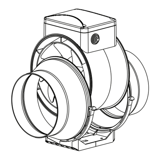
- Page 3 1m straight ducting to the motor body (see fig.B). min 1m g. A horizontal on a wall g. B horizontal on a oor Do not mount vertically 2. Using a screw driver, remove 3. Remove bracing clips & remove central unit. screws on clips. hib.co.uk...
-
Page 4: Electrical Connection
4. Place frame in desired 5. Fix frame to desired surface, using fixings suitable for location and mark fixing wall type. Then replace central unit and bracing clips. holes. 6. Connect the flexible ducting to both sides of the Inline fan with the metal hose clamps. Ensure there is a minimum of 1m straight ducting between fascia and fan. - Page 5 5. Amend the timer setting, if desired, following the process on page 6. Replace cover using a suitable screw driver. 6. On Illuminated versions (32600, 33800, 32700 & 33700) the mains supply should be connected to the LED driver as per the wiring diagram for lamp (Fig. D).
- Page 6 Timer System Warning! The timer circuit is under mains voltage. Ensure mains power supply is switched off before making any adjustments. The fan is operational after the control voltage is supplied by the external switch (e.g., by the light switch) to the input terminal LT. After the fan is switched off the fan continues to operate within the timer period set by the timer from 2 to 30 minutes.
- Page 7 Avoid water dripping on the electric components. Wipe the surfaces dry after cleaning. Technical Information Power Input: 220-240V, 50/60Hz Maximum Ventilation Volume: 210 m3/hr (±5%) / 58.333 Litres Per Second Power Consumption: 25W + 3W LED Lamp (32600, 33800, 32700 & 33700 only) Decibel: 32dB Dimensions: Ø14 x D7.3cm hib.co.uk...
- Page 8 ©HiB Copyright: No part of this document may be reprinted or duplicated without HiB consent. All sizes and measurements are approximate, but we do try and make sure they are as accurate as possible. In the interest of continuous product development, HiB reserves the right to alter specifications as necessary. E & OE.
Need help?
Do you have a question about the 32600 and is the answer not in the manual?
Questions and answers