Table of Contents
Advertisement
Advertisement
Table of Contents

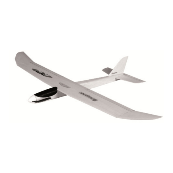
Summary of Contents for GRAUPNER PEP 4318
- Page 1 Manual R/C electric airplane No. 4318...
-
Page 3: Table Of Contents
Index Introduction ................5 Service centre ................5 Intended use ................6 Glue ..................6 Parts list No. 4318 ..............6 Technical data ................8 Required tools and facilities (not included) ......8 Recommended accessories (not included) ......8 Assembly step 1 ............... 9 Assembly step 2 ............... - Page 4 Assembly step 23 ..............16 Assembly step 24 ..............17 Assembly step 25 ..............17 Assembly step 26 ..............17 Symbol description ..............18 Safety notes................18 Package content ..............19 Care and maintenance ............19 Warranty conditions .............. 19...
-
Page 5: Introduction
This manual is part of that product. It contains important informa- tion concerning operation and handling. Keep these instructions for future reference and give it to third person in case you gave the product. Service centre Graupner Central Service Servicehotline Graupner/SJ GmbH (+49) (0)7021/722-130 Henriettenstraße 96... -
Page 6: Intended Use
Read through this entire manual before you attempt to install or use the PEP. Graupner/SJ constantly works on the development of all products; we reserve the right to change the item, its technology and equip- ment. - Page 7 Triangle stick Balsa 60 x 7 x7 Support Plywood Laser part 3 Captive nut Steel Polyester band Polyester 80 x 15 x 0,2 Fuselage side part right 1 Balsa Laser part 3 Fuselage side part left Balsa Laser part 3 Pushrod tube Plastic Ø...
-
Page 8: Technical Data
Rudder hinge Plastic 270 x 20 x (not included) Sunk-head screw Polyamide M3x16 Decals sheet Self- 180 x 65 x gluing film Angle template 88° Plywood Laser part 3 Support Balsa Laser part 3 Sanding block Hardwood 120x40x20 Technical data Wingspan approx. -
Page 9: Assembly Step 1
Assembly step 1 First mark a straight line in the middle of the construc- tion board, then cover the construction board with transparent film so that no parts stick to it. Fasten the fuselage bottom (1) and (3) as well as the cover (2) con- gruently. -
Page 10: Assembly Step 10
Assembly step 4 After hardening the wood glue, carefully remove the fuselage from the construc- tion board. Sand the outer sides of the fuselage with the sanding block (54) using the coarse grained side. Do not sand off the protruding noses of part (53). -
Page 11: Assembly Step 12
Assembly step 6 Cut off the ends of the poly- ester tape protruding below and cut the tape over the nuts (13). Try to install the elevator servo from RC drive set No. 4318.90 (No. 4318.90 is not included in the quick- kit No. -
Page 12: Assembly Step 15
(35) with the sanding block. To check, attach the wing to the building board as shown in the figure and place part (20). Please note, the small radius is on the underside of the wing, the top is profiled to a depth of about 15 mm finished with a large radius. -
Page 13: Assembly Step 17
The disc (26) serves as a template. First round off the fuselage edges with the balsa plane, then with the coarse-grained side of the sanding block (54). Make sure that the left and right sides evenly rounded by removing the cover (2). -
Page 14: Assembly Step 18
Assembly step 12 Insert the prepared tail units into the fuselage and align them exactly, place the wing (35) on the fuselage for con- trol, sight from the front whether the rudder is verti- cal and the elevator is paral- lel to the wing. -
Page 15: Assembly Step 15
Assembly step 15 Bevel the leading edge of reinforcement (41) before sticking. Then stick together with the holes in the wing (35). Check that the end edge is parallel to the wing leading edge and check the triangle ruler. Lower the holes for the screws (50) so that the screw heads do not protrude. Assembly step 16 Cut off the end strips (38/39) and glue them on, the under-... -
Page 16: Assembly Step 23
Assembly step 20 The illustration shows the fully installed aileron servos. Insert the slots for the rud- der horns (33) with the balsa cutter into the ailerons (40). Cut off the aileron linkage (rest part of (32)) and trim off with a pair of flat nose pli- ers at the end, first push on the reinforcement (44) and glue with superglue. - Page 17 Fly the model with neutral control surfaces in calm or light wind. An obstacle-free meadow is ideally suited as a terrain. Start the model into the air by hand against the wind direction. GRAUPNER Modellbau wishes many beautiful flights with the PEP model 17 / 20...
-
Page 18: Symbol Description
Symbol description Always observe the information indicated by this warning sign. Par- ticularly those which are additionally marked with the words CAU- TION or WARNING. The signal word WARNING indicates the potential for serious injury, the signal word CAUTION indicates pos- sibility of lighter injuries. -
Page 19: Package Content
The present construction or user manual is for informational pur- poses only and may be changed without prior notice. The current version can be found on the Internet at www.graupner.de on the rel- evant product page. In addition, the company...


Need help?
Do you have a question about the PEP 4318 and is the answer not in the manual?
Questions and answers