Table of Contents
Advertisement
Quick Links
Advertisement
Table of Contents

Related Manuals for Williams Sound DL102


Summary of Contents for Williams Sound DL102
- Page 1 PDF provided by Conference Room AV Williams Sound DL 102 Counter Loop Amplifier for T-Coil Hearing Devices...
- Page 2 DL102 Counter Loop Amplifier USER MANUAL MAN 234A...
-
Page 3: Table Of Contents
Contents Overview ............................3 System Includes ........................3 Maintenance and Recycling Instructions ................. 3 Safety Information ........................... 4 Quick Setup ............................5 Setup ..............................6 Loop Amplifier .........................6 Wiring a Counter ........................6 Connect Loop Wire to the Loop Output Terminals .............6 Placing a Loop Mat ........................6 Connect Audio Outputs to Loop Amplifier Inputs ............8 Connect Power to the Amplifier ..................9 Operation ............................ -
Page 4: Overview
Audio is wired into the DL102 amplifier via a line input or microphone. Audio is fed from the amplifier through the loop wire in the area where a T-coil hearing device can pick-up the audio. -
Page 5: Safety Information
Safety Information Servicing or attempting to service this device will void the warranty Refer servicing to qualified personnel. Servicing is required when the system has been damaged in any way: if liquid has been spilled or objects have fallen into the unit, if the unit has been exposed to moisture, if the unit does not operate normally, or if the unit has been dropped. -
Page 6: Quick Setup
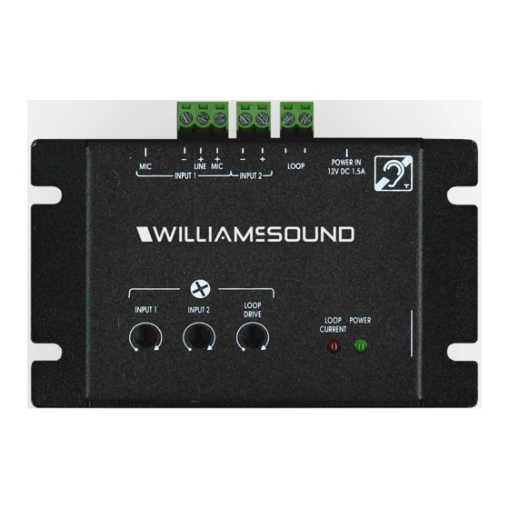
400 mA/m in the looped area to meet the IEC 60118-4 specification. 8. Switch your hearing device to be in T-coil mode (follow instructions for your specific Phoenix style connector Phoenix style connector hearing device). Front Figure 1: Controls for the DL102... -
Page 7: Setup
Setup Important: Always disconnect the unit from power before making connections. Loop Amplifier Place the amplifier in a convenient, well-ventilated area near the audio source so that all of the necessary connections can reach the amplifier. Wiring a Counter There are several configurations for wiring a loop for a counter top or similar area. We recommend the loop be placed on both the flat top and vertical face of the counter. - Page 8 Loop Loop Amplifier Amplifier Amplifier Amplifier Loop Loop Figure 2: Various Counter Placements...
-
Page 9: Connect Audio Outputs To Loop Amplifier Inputs
Phoenix style connector Front Figure 3: The phoenix style connectors at the top of the DL102. Note: For Input 1, the phoenix style connector is not for use with balanced audio; there is not a gnd connection. Instead, there is a microphone + line in. Use Line + for Line level... -
Page 10: Connect Power To The Amplifier
Microphones (optional) The MIC 103 is included with the DL102. Several other microphones can be used as well, such as the Williams Sound MIC 027 and STD 005. See the Williams AV website for all microphone options. A microphone can be used at the same time as the line inputs to monitor other sounds, such as a doorbell or telephone ringer. -
Page 11: Operation
Operation When connecting power to your amplifier for the first time, the power LED will illuminate green and the amplifier will be on. 1. Set the audio equipment to normal listening level for the other listeners in the room. 2. Switch your hearing aid to T-coil mode. 3. -
Page 12: Troubleshooting
Troubleshooting PROBLEM SOLUTION No Sound -Check all connections -Microphone or audio source not connected -Hearing aid not on the T-coil setting -Volume is muted Low Sound -Microphone too far from sound -Loop wire not connected correctly -Volume set too low Distorted Sound -Volume control set too high. -
Page 13: Specifications
Specifications 3 (1 microphone or line input, isolated line input, Mic) Audio Input 3.5mm jack, Mic-2 pole line in, 3 pole line in, Mic in Connector Type 12V DC 1.5 A output Power Supply 100-240VAC, 50/60Hz - 2.0A Input Power Voltage >... - Page 14 This page is intentionally left blank.
-
Page 15: Warranty
Williams AV warrants the DL102 amplifier against defects in materials and workmanship for TWO (2) years. During the first two years from the purchase date, we will promptly repair or replace the product. - Page 16 Pack the system carefully and send it to: Williams AV Attn: Repair Dept. 10300 Valley View Road Eden Prairie, MN 55344 USA Your warranty becomes effective the date you purchase your system. If your sales receipt is not available, the date code on the product will determine your warranty status.
- Page 17 info@williamsav.com / www.williamsav.com 800-843-3544 / INTL: +1-952-943-2252 © 2018, Williams AV, LLC MAN 234A...
Need help?
Do you have a question about the DL102 and is the answer not in the manual?
Questions and answers