Table of Contents
Advertisement
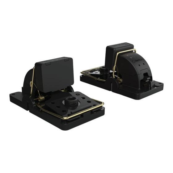
Rat Riddance Connect
Instruction Manual
This manual is based on the latest information and is provided subject to alteration.
We reserve the right to change the construction and/or confi guration of the product
and versions at any time without obligation.
All rights reserved. No part of this document may be reproduced, stored in a database or any other retrieval
system, or published, in any form or way, electronically, mechanically, digitally per photo print or microfi lm or
any other way without written permission from the author.
Advertisement
Table of Contents

Subscribe to Our Youtube Channel
Related Manuals for Rentokil Rat Riddance Connect


Summary of Contents for Rentokil Rat Riddance Connect
- Page 1 Rat Riddance Connect Instruction Manual This manual is based on the latest information and is provided subject to alteration. We reserve the right to change the construction and/or confi guration of the product and versions at any time without obligation.
-
Page 2: Table Of Contents
Contents Introduction Safety Instruction Caution Attention Product Description Product Functions Limitation of Liability & Damages Product Disposal Environmental Restrictions Operational Notices Trap Features Installation Process Prior to Installation Components for Installation Fitting the Lanyard Site Installation Installing the Batteries... -
Page 3: Safety Instruction
Introduction Rat Riddance Connect is a discreet, non-toxic solution to rat control. Designed specifically for high risk market segments where even a single rat cannot be tolerated. Rat Riddance Connect is suitable for food and pharmaceutical manufacturers, hospitality, educational, health establishments and general pest control. -
Page 4: Product Description
Product Description Rat Riddance Connect is a stand alone, designed by Rentokil for both indoor battery powered trapping device and outdoor use to provide a non tox that has been designed to efficiently solution against travelling rats. Correctly capture, kill and contain rodents. -
Page 5: Limitation Of Liability & Damages
The product described in this manual is subject to continuous development and improvement and Rentokil reserve the right to alter the specification or design without prior notice. Rentokil cannot accept any liability for any loss or damage arising from the use of any information contained within this manual, or from any incorrect use of the product described herein. -
Page 6: Environmental Restrictions
Environmental Restrictions Environmental Details Restrictions Excessive levels The product has been validated to IP65* of surface water and is therefore suitable for indoor outdoor use. In the event of extreme flood conditons greater than 100mm for a prolonged period, damage to the device or radio functionality may occur. -
Page 7: Operational Notices
Operational Notices Note: Trapping can be dangerous and can cause injury. Ensure the trap is in a disarmed state before carrying out servicing. Take care not to trap your fi ngers Armed Disarmed 1. Ensure neoprene or rubber gloves are used when setting up and handling. -
Page 8: Trap Features
Trap Features 1. Understanding the Trap’s Features User Interaction: Status LED 2. Signal LED 3. Magnetic Switch 4. Paddle Activation Switch 5. Trap Armed Switch 6. Trap Base Trap Break Back Arm 8. Bait Tray Internal Features To Be Aware of: The Module features a number of switch sensors which detect the trap status: Item 4. -
Page 9: Installation Process
Retain the equipment and packing materials for inspection. Check that all parts have been received as ordered. 2. Components for Installation 1. Rat Riddance Connect Main Assembly 2. Rat Riddance Connect Snap Trap 3. -
Page 10: Fitting The Lanyard
Only use Lanyard if retention is required. 4. Site Installation Rat Riddance Connect trapping devices can be sited along wall / floor junctions, behind machinery and equipment, in accordance with correct Pest Service technician guidelines. Care should be taken to site the devices in the most suitable way. -
Page 11: Installing The Batteries
5. Installing the Batteries Ensure the correct battery pole orientation Ensure the trap is disarmed, then remove Fit 3x AAA batteries and replace the Main Assembly from shoe using RI Service battery door, check the LED’s status. Key and remove the battery door. LED Start-Up Sequence: Code: Status LED... -
Page 12: Service Process
Note: Ensure trap is in disarmed state before handling and all actions Service Process performed before re-arming Assess Trap Status: CATCH: Dispose of catch into black & yellow waste bag NO CATCH Disarm the trap before continuing Clean & Re-Bait: Clean trap in accordance with standard cleaning procedure and refi ll the bait tray. -
Page 13: Using The Interface
Using the Interface 1. Using the Service Key Note: Ensure trap is disarmed before using RI Key Use the RI Key Magnet to activate the Interface Active Magnet Zone 2. LED Icon Code Trap Status Indicator Trap Connection Indicator 3. Service Modes Hold the magnet close to the RI Icon, the Status light fl ashes when recognised: Blue for fi rst 5 seconds = Service Visit... -
Page 14: Radio Restart
Using the Interface (Continued) 5 - 10 Secs 5. Radio Restart To force the radio to restart the connection process to the control panel, hold the magnet over the device for between 5 and 10 seconds. Only remove the magnet when the fl ashing status LED has changed from blue to yellow. -
Page 15: Testing The Paddle Switch
Using the Interface (Continued) 7. Testing the Paddle Switch Test the paddle activation switch by pressing the paddle. If the switch is working effectively the Status LED will be yellow each time the paddle is pressed. Note: Ensure trap is disarmed before pressing the paddle 8. -
Page 16: Module Warnings
Using the Interface (Continued) 9. Module Warnings Low Battery When initially powered the Status LED will flash rapidly Red for low battery for 20 seconds or when arming the device the Status LED will flash red rapidly for 20 seconds. No Signal Trap Connection Indicator will flash red every 3 seconds if there is no signal and no connection. -
Page 17: Troubleshooting Fixes
Using the Interface (Continued) 10. Troubleshooting Fixes No Radio Connection: If the device is not connected to the Control Panel, the radio can be forced to restart by using the Radio Restart mode (See Page 14). The device will automatically restart the radio over time, but this step will force an immediate Radio Restart. -
Page 18: Further Information
-20ºC to 50ºC ( -4ºF to 122ºF) Environmental rating Target IP65 Connect Details Interface 868-928MHz depending on local Approvals Rentokil Initial Propriatary Application Layer Protocol Max Number of 300 per control panel Rat Riddance Connect Product Code Summary Accessories 304751... -
Page 19: Approvals
Approvals FCC PART15 CLASS B, CE and RoHS compliant FCC Warning Statement: • This device complies with Part 15 of the FCC Rules. Operation is subject to the following two conditions: (1) This device may not cause harmful interference, and (2) This device must accept any interference received, including interference that may cause undesired operation. - Page 20 Rentokil reserve the right to alter the specification or design without prior notice. Rentokil cannot accept any liability for any loss or damage arising from the use of any information contained within this manual, or from any incorrect use of the product described herein.
Need help?
Do you have a question about the Rat Riddance Connect and is the answer not in the manual?
Questions and answers