Table of Contents
Advertisement
Advertisement
Table of Contents

Related Manuals for Spirotech SpiroVent Superior S6 Series


Summary of Contents for Spirotech SpiroVent Superior S6 Series
-
Page 2: Table Of Contents
Risk of electric shock Spirotech bv. This manual has been composed with the utmost care. Should, however, this manual contain any inaccuracies, Risk of burning Spirotech bv cannot be held responsible for this. User manual - version 1.1 English... -
Page 3: Introduction
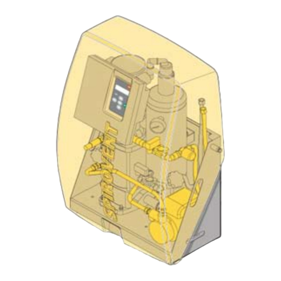
OBJ_DOKU-75-001.fm Page 22 Thursday, January 29, 2009 1:34 PM INTRODUCTION Overview of the unit Superior S6A Superior S6A-R 2P Superior S6A-R Automatic air vent Main pump Deaeration vessel Adjustable outlet valve Inlet hose Pressure sensor Refill connection (types S6A-R and S6A-R 2P) SmartSwitch (in bottom of control unit) Valve behind pressure gauge Pressure switch... - Page 4 OBJ_DOKU-75-001.fm Page 23 Thursday, January 29, 2009 1:34 PM Operation The figure below schematically shows the operation of the unit. The letter indications comply with the main figure on the previous page. S6A-R S6A-R 2P User manual - version 1.1 English...
-
Page 5: Technical Specifications
OBJ_DOKU-75-001.fm Page 24 Thursday, January 29, 2009 1:34 PM 2.2.1 General The unit should be used within the limits of the technical The Superior is a fully automatic vacuum degasser for specifications as given in chapter 3. installations filled with fluid. The fluid contains dissolved and undissolved gases. - Page 6 OBJ_DOKU-75-001.fm Page 25 Thursday, January 29, 2009 1:34 PM General specifications S6A-R S6A-R 2P Max. system volume 150 m 150 m 150 m Empty weight 57 kg 59 kg 67 kg Volume of degassing vessel Inlet connection Swivel G¾” f.t. Swivel G¾”...
-
Page 7: Safety
Temperature Serial number Year of manufacture WARNING SPIROTECH bv – Helmond – The Netherlands There are hot parts below the cover. Let the unit cool down before starting the activities. CE marking The unit has a CE marking. This means that the unit has... -
Page 8: Installation And Commissioning
OBJ_DOKU-75-001.fm Page 27 Thursday, January 29, 2009 1:34 PM INSTALLATION AND Installation and mounting COMMISSIONING CAUTION Install the unit in accordance with the • Installation conditions local guidelines and rules. Install the unit on a frost-free, well-ventilated place. • Install the unit as bypass on the main •... - Page 9 OBJ_DOKU-75-001.fm Page 28 Thursday, January 29, 2009 1:34 PM 5.3.2 Installation With the types S6A-R and S6A-R 2P: Insert a valve (F) and a non-return protection (E) in Mechanical the refill fluid supply line. Connect the supply line to the refill connection (G) of the unit.
- Page 10 OBJ_DOKU-75-001.fm Page 29 Thursday, January 29, 2009 1:34 PM Set the adjustment valves (A and B) from the position "fully open" with the following table. Open the valve (C) behind the pressure gauge (D). Open the valves (E and F) in the inlet and outlet lines.
- Page 11 OBJ_DOKU-75-001.fm Page 30 Thursday, January 29, 2009 1:34 PM Follow the procedures given below for entering the Check operation required parameters. Set date en time Press O Select a language using . Press E NTER Set the date using . Press E NTER Set the day using .
- Page 12 OBJ_DOKU-75-001.fm Page 31 Thursday, January 29, 2009 1:34 PM Press M . Select User menu > Manual Parameter Description operation using . Press E NTER Block.time day 2 See Block.time day 1. Select Manual operation > system fill Block.time week Days of the week on which the unit using .
-
Page 13: Use
OBJ_DOKU-75-001.fm Page 32 Thursday, January 29, 2009 1:34 PM Press M . Select User menu > General info With the types S6A-R and S6A-R 2P: • using . Press E The amount of fluid that is added (B) depends on NTER Select an item using . -
Page 14: Failures
OBJ_DOKU-75-001.fm Page 33 Thursday, January 29, 2009 1:34 PM FAILURES Putting out of operation Remedy failures WARNING In case of failure always warn the • installer. • Remove the voltage and pressure from the unit before starting the activities see §... - Page 15 OBJ_DOKU-75-001.fm Page 34 Thursday, January 29, 2009 1:34 PM Failure table General The letter indications comply with the main figure in § 2.1. An overview of the replacement parts has been included in § 8.2. Problem Possible cause Correction The temperature of the system fluid is Provide a temperature of >...
- Page 16 OBJ_DOKU-75-001.fm Page 35 Thursday, January 29, 2009 1:34 PM Specific for types S6A-R and S6A-R 2P Problem Possible cause Correction A failure in the installation. Provide a system pressure of > 1 bar. Err 1 Psystem too low The system pressure is below 1 bar. There is a leak in the installation.
-
Page 17: Maintenance
OBJ_DOKU-75-001.fm Page 36 Thursday, January 29, 2009 1:34 PM MAINTENANCE Periodic maintenance Annually replace the interior of the solenoid valves (N). Replacement parts The letter indications comply with the main figure in § 2.1. Article number Letter Description 15.552 Shaft sealing for pump type CR1-13/1-9 AAA HQQE 15.553 Gasket set for pump type CR1-9 and CR1-13 15.554... - Page 18 OBJ_DOKU-75-001.fm Page 37 Thursday, January 29, 2009 1:34 PM Maintenance card Type: Serial number: Installation date: Installed by firm: Installed by technician: Inspection date: Technician: Initials: Nature of the maintenance: Inspection date: Technician: Initials: Nature of the maintenance: Inspection date: Technician: Initials: Nature of the maintenance:...
-
Page 19: Guarantee
Declaration of conformity EU declaration of conformity We, Spirotech bv, Churchilllaan 52, Helmond NL, declare entirely on our own responsibility that the products SpiroVent Superior S6A / S6A-R / S6A-R 2P to which this declaration applies, comply with the standards: EN 292-1, EN 292-2, EN 809, EN 60204-1, EN60335-1, EN 55014-1 and EN 55014-2, EN 61000-3-2, EN 61000-3-3, EN 61000-6-2 and EN 61000-6-4. - Page 20 The manufacturer reserves the right to make changes without prior notification. © Copyright Spirotech bv Information given in this brochure may not be reproduced complete or in part without the prior written consent of Spirotech bv. Spirotech bv The Netherlands...
Need help?
Do you have a question about the SpiroVent Superior S6 Series and is the answer not in the manual?
Questions and answers