Table of Contents
Advertisement
Quick Links
HM-5140-3
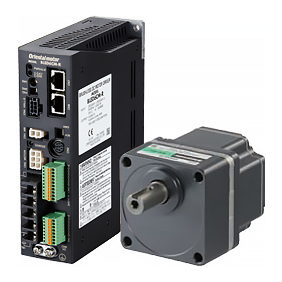
Brushless Motor and Driver Package
BLE Series
RS-485 communication type
USER MANUAL
(Motor)
(Driver)
Thank you for purchasing an Oriental Motor product.
This Operating Manual describes product handling procedures and safety precautions.
• Please read it thoroughly to ensure safe operation.
• Always keep the manual where it is readily available.
Advertisement
Table of Contents
Troubleshooting

Related Manuals for Orientalmotor BLE23AR*S Series


Summary of Contents for Orientalmotor BLE23AR*S Series
- Page 1 HM-5140-3 Brushless Motor and Driver Package BLE Series RS-485 communication type USER MANUAL (Motor) (Driver) Thank you for purchasing an Oriental Motor product. This Operating Manual describes product handling procedures and safety precautions. • Please read it thoroughly to ensure safe operation. •...
-
Page 2: Table Of Contents
Entry Explanation of I/O signals ......44 Assignment of direct I/O ......44 Operating Manuals for the BLE Series ..6 „ Assignment to the input terminals .....44 „ Changing the logic level setting of input Introduction ........... 7 signals ...............45 „... - Page 3 Method of control via „ Input/output of remote I/O ........118 „ Details of remote I/O assignment ....120 Modbus RTU Method of control via MECHATROLINK (RS-485 communication) communication .......... 122 Guidance ........... 122 Guidance ............76 Setting the switches........125 2 Communication specifications ....79 I/O field map for the NETC01-M2 .....
- Page 4 Reference 1 Specifications ..........150 Specifications ..........150 General specifications ....... 152 Dimension..........152 Standard and CE Marking ......153 Installing and wiring in compliance with EMC Directive ........155 Appendix Accessories (sold separately) ....160 Related products (sold separately) ..162 −4−...
- Page 5 1 Entry This part explains the composition of the operating manuals, the product overview, specifications and safety standards as well as the name and function of each part and others. Table of contents 1 Operating Manuals for the BLE Series ..........6 2 Introduction ..........7 3 Safety precautions .......8 4 Precautions for use ......10...
-
Page 6: Operating Manuals For The Ble Series
Operating Manuals for the BLE Series 1 Operating Manuals for the BLE Series Operating manuals for the BLE Series FLEX RS-485 communication type are listed below. After reading the following manuals, keep them in a convenient place so that you can reference them at any time. Applicable product Type of operating manual Model... -
Page 7: Introduction
Introduction 2 Introduction „ Before use Only qualified and educated personnel should work with the product. Use the product correctly after thoroughly reading the section p.8 "3 Safety precautions". The product described in this manual has been designed and manufactured to be incorporated in general industrial equipment. -
Page 8: Safety Precautions
Safety precautions 3 Safety precautions The precautions described below are intended to prevent danger or injury to the user and other personnel through safe, correct use of the product. Use the product only after carefully reading and fully understanding these instructions. Handling the product without observing the instructions that accompany a "Warning"... - Page 9 Safety precautions • Do not use the product in conditions exceeding the motor (gearhead) or driver specifications. Doing so may result in electric shock, fire, injury or equipment damage. • Do not insert an object into the openings in the driver. Doing so may result in fire, electric shock or injury. •...
-
Page 10: Precautions For Use
Precautions for use 4 Precautions for use This chapter explains the restrictions and other items you should take heed of when using the BLE Series FLEX RS- 485 communication type. • Connect protective devices to the power line Connect a circuit breaker or earth leakage breaker to the driver’s power line to protect the primary circuit. If an earth leakage breaker is to be installed, use one incorporating high-frequency noise elimination measures. - Page 11 Precautions for use • Saving data to the non-volatile memory Do not turn off the 24 VDC power supply while writing the data to the non-volatile memory, and also do not turn off within 5 seconds after the completion of writing the data. Doing so may abort writing the data and cause a EEPROM error alarm to generate.
-
Page 12: System Configuration
System configuration 5 System configuration An example of system configuration using the BLE Series FLEX RS-485 communication type is shown below. Illustration shows the electromagnetic brake type. Data setter OPX-2A (accessory) Motor Driver PC in which the data editing software MEXE02 Connection has been installed cable... -
Page 13: Preparation
Preparation 6 Preparation This chapter explains the items you should check, as well as the name and function of each part. 6.1 Checking the product Verify that the items listed below are included. Report any missing or damaged items to the branch or sales office from which you purchased the product. -
Page 14: Combination Tables
Preparation 6.3 Combination tables • in the model names indicates a number representing the gear ratio. • • „ indicates a number representing the length of a connection cable. • • The combination types come with the motor and gearhead pre-assembled. „... -
Page 15: Names And Functions Of Parts
Preparation 6.4 Names and functions of parts „ Motor Illustration shows the electromagnetic brake type. Motor Pilot Output shaft Mounting hole (4 locations) Protective Earth Terminal Be sure to ground. Motor cable Motor power connector Electromagnetic brake connector Motor signal connector −15−... - Page 16 Preparation „ Driver Mounting hole (at the back) PWR/ALM LED C-DAT/C-ERR LED RS-485 communication connector Address number setting switch (SW1) (CN7/CN8) Test operation mode switch (SW2) Motor signal connector (CN4) Function setting switch1 (SW3) Electromagnetic brake connector (CN1) Data edit connector (CN3) CHARGE LED Motor connector (CN2) Input signal connector (CN5)
- Page 17 Preparation Name Description Ref. SW2-No.1: This switch is used to check the connection between the motor and driver before establishing a communication. When having connected properly, setting the SW2-No.1 to the ON side causes the motor to rotate at low speed in p.39 Test operation mode switch the forward direction.
- Page 18 −18− 1 Entry...
- Page 19 2 Installation and connection This part explains the installation method of the product, the mounting method of a load and the connection method as well as I/O signals. Table of contents 2.6 Selecting the input signal power 1 Installation ..........20 supply ............
-
Page 20: Installation
Installation 1 Installation This chapter explains the installation location and installation methods of the motor and driver, as well as how to install a load and external potentiometer. 1.1 Installation location The motor and driver are designed and manufactured for use as a component to be installed inside equipment. Install them in a well-ventilated location that provides easy access for inspection. - Page 21 Installation „ Installing the combination type • hollow shaft flat gearhead A combination type • hollow shaft flat gearhead can be installed by using Mounting plate Front either its front or rear side as the mounting surface. Install the supplied Hollow shaft hexagonal socket head screw set in the four mounting holes you drilled and flat gearhead tighten the nuts until no gaps remain between the motor and mounting plate.
-
Page 22: Installing The Combination Type • Parallel Shaft Gearhead
Installation 1.3 Installing the combination type • parallel shaft gearhead „ Mounting hole dimensions [unit: mm (in.)] Model ØA ØB ØD BLE23 70 (2.76) 24 (0.94) 10 (0.39) 4.5 (0.177) BLE46 94 (3.70) 34 (1.34) 13 (0.51) 6.5 (0.256) BLE512 104 (4.09) 40 (1.57) 18 (0.71) -
Page 23: Installing The Round Shaft Type
Installation 1.4 Installing the round shaft type „ Mounting plate size Install the motor to a mounting plate of the following size or larger, so that the motor case temperature will not exceed 90 °C (194 °F). Model Size of mounting plate Thickness Material BLE23... - Page 24 Installation „ Using the rear side as the mounting surface Safety cover Hexagonal socket head screw Safety cover mounting screw (M3) • Mounting hole dimension ØD or more Mounting plate 4×ØC Flat washer Spring washer Hexagonal nut Mounting hole dimensions [unit: mm (in.)] Model ØA ØC...
-
Page 25: Installing A Load To The Combination Type • Parallel Gearhead Or Round Shaft Type
Installation • Do not forcibly assemble the motor and gearhead. Also, do not let metal objects or other foreign Note matters enter the gearhead. The pinion of the motor output shaft or gear may be damaged, resulting in noise or shorter service life. •... -
Page 26: Installing A Load To The Combination Type • Hollow Shaft Flat Gearhead
Installation 1.7 Installing a load to the combination type • hollow shaft flat gearhead If the motor is subject to a strong impact upon instantaneous stop or receives a large overhung load, use a stepped load shaft. • Apply grease (molybdenum disulfide grease, etc.) on the surface of the load shaft and inner Note walls of the hollow output shaft to prevent seizure. - Page 27 Installation • Recommended load shaft installation dimensions [Unit: mm (in.)] Recommended Outer diameter Inner diameter of Nominal diameter Applicable Spacer Model diameter of load of stepped shaft hollow shaft (H8) of retaining ring screw thickness shaft (h7) (ØD) +0.027 Ø12 Ø12 -0.018 BLE23...
-
Page 28: Permissible Radial Load And Permissible Axial Load
Installation 1.8 Permissible radial load and permissible axial load Make sure the radial load and axial load received by the motor (gearhead) output shaft will not exceed the allowable values shown in the table below. If the radial load or axial load exceeds the specified allowable value, repeated load applications Note may cause the bearing or output shaft of the motor (gearhead) to undergo a fatigue failure. -
Page 29: Installing The Driver
Installation 1.9 Installing the driver 35 (1.38) 20 (0.79) or more The driver is designed so that heat is dissipated via air convection and conduction through the enclosure. Install the driver to a flat metal plate offering excellent vibration resistance. When two or more drivers are to be installed side by side, provide 20 mm (0.79 in.) and 25 mm (0.98 in.) clearances in the horizontal and vertical directions, respectively. -
Page 30: Installing The External Potentiometer (Supplied)
Installation Removing from DIN rail Pull the DIN lever down until it locks using a flat tip screwdriver, and lift the bottom of the driver to remove it from the rail. Use force of about 10 to 20 N (2.2 to 4.5 lb.) to pull the DIN lever to lock it. Excessive force may damage the DIN lever. -
Page 31: Connection
Connection 2 Connection This chapter explains how to connect the driver and motor, I/O signals, and power supply, as well as the grounding method. 2.1 Connection example The following figure is a connection example when an electromagnetic brake motor is used. Motor signal connector Connect to CN4 Grounding... -
Page 32: Connecting The Power Supply
Connection 2.2 Connecting the power supply Connect the power cable to the main power supply input terminals (TB1) on the driver. The product does not come with a power cable. It must be supplied by the user. Power supply input Connecting method Single-phase 100-120 V Connect the live side to terminal L, and the neutral side to terminal N. -
Page 33: Connecting The Motor And Driver
Connection 2.4 Connecting the motor and driver Connect the motor power connector to the CN2, and the motor signal connector to the CN4 on the driver. When using an electromagnetic brake type motor, also connect the electromagnetic brake connector to the CN1. When extending the connection distance between the motor and driver, use the connection cable (supplied or accessory). -
Page 34: Connecting The 24 Vdc Power Supply
Connection 2.5 Connecting the 24 VDC power supply The 24 VDC power supply is for the control circuit of the driver. Be sure to connect a power supply which voltage is 24 VDC −15% to 24 VDC +20% and current is 1 A or more, to the CN5. power supply •... - Page 35 Connection „ CN6 pin assignment Description ∗2 Pin No Name Analog external speed setting input VL ∗1 • • • IN-COM1 Input signal common (0 V) • Output terminal 0 (+) [SPEED-OUT] • OUT0+ OUT0− Output terminal 0 (−) [SPEED-OUT] Output terminal 1 (+) [ALARM-OUT1] OUT1+ OUT1−...
- Page 36 Connection „ Connection example with I/O signal circuit • Sink logic circuit Master controller Driver 5.1 kΩ 820 Ω 5.1 kΩ 820 Ω 5.1 kΩ 820 Ω 5.1 kΩ 820 Ω 5.1 kΩ 820 Ω 5.1 kΩ 820 Ω 5.1 kΩ 820 Ω...
-
Page 37: Connecting An External Speed Setter
Connection • Source logic circuit Master controller Driver 24 VDC 5.1 kΩ 820 Ω 5.1 kΩ 820 Ω 5.1 kΩ 820 Ω 5.1 kΩ 820 Ω 5.1 kΩ 820 Ω 5.1 kΩ 820 Ω 5.1 kΩ 820 Ω 24 VDC 30 VDC or less 40 mA or less 40 mA or less... -
Page 38: Connecting The Data Setter
Connection 2.9 Connecting the data setter Connect OPX-2A cable or supplied cable with OPX-2A cable or supplied the MEXE02 to CN3 on the driver. cable with the MEXE02 The data edit connector (CN3), I/O signal connectors (CN5/CN6) and RS-485 communication connectors (CN7/CN8) are not insulated. When grounding the positive terminal of the power supply, do not connect any equipment (PC, etc.) whose negative terminal is grounded. -
Page 39: Test Operation
Connection 2.11 Test operation Once a main power supply and 24 VDC power supply are connected, the connection status can be checked by driving the motor tentatively without setting the data. 1. Turn on the main power supply and 24 VDC power supply after completing the wiring. 2. - Page 40 Connection „ Regeneration unit specifications EPRC-400P Model Continuous regenerative power 100 W 400 Ω Resistance Operating temperature of Operation: Opens at 150±7 °C (302±45 °F) thermostat Reset: Closes at 145±12 °C (293±54 °F) (normally closed) Electrical rating of thermostat 120 VAC 4 A, 30 VDC 4 A (minimum current: 5 mA) −40−...
-
Page 41: Connection Diagram (Example)
Connection 2.13 Connection diagram (example) Each connection diagram (example) is for the electromagnetic brake type. In the case of the standard type, there are no connection for the electromagnetic brake and no connection/input for the MB-FREE input signal. To use the built-in power supply, set the SW3-No.3 of the SW3-No.3 function setting switch switch1 to the ON side. - Page 42 Connection • Using an external power supply This is a connection example that the power supply is single-phase 100-120 VAC, the rotation speed is set using an external potentiometer or external DC voltage, and the motor is operated with sequence connection of transistor type. For the SPEED-OUT output, supply at least 5 mA of current.
- Page 43 Connection „ Source logic This is a connection example that the power supply is single-phase 100-120 VAC, the rotation speed is set using an external potentiometer or external DC voltage, and the motor is operated with sequence connection of transistor type. For the SPEED-OUT output, supply at least 5 mA of current.
-
Page 44: Explanation Of I/O Signals
Explanation of I/O signals 3 Explanation of I/O signals In this manual, I/O signals are described as follows. • Direct I/O: I/O signals accessed via input signal connector (CN5) and I/O signal connector (CN6) • Network I/O: I/O signals accessed via RS-485 communication Set the following parameters using any of the OPX-2A, MEXE02 or RS-485 communication. -
Page 45: X84; Changing The Logic Level Setting Of Input Signals
Explanation of I/O signals Related parameters Parameter name Description Initial value IN0 function select 1: FWD IN1 function select 2: REV Assigns the input signals to the input IN2 function select 19: STOP-MODE terminal IN0 to IN6. IN3 function select See the table on the previous page for the 48: M0 assignment number and corresponding... -
Page 46: X84; Assignment To The Output Terminals
Explanation of I/O signals „ Assignment to the output terminals The output signals shown below can be assigned to the output terminals OUT0 and OUT1 of CN6 by setting parameters. For details on output signals, refer to p.52. Output terminal Initial value OUT0 85: SPEED-OUT... -
Page 47: Assignment Of Network I/O
Explanation of I/O signals 3.2 Assignment of network I/O Assign the I/O function via RS-485 communication. „ Assignment of input signals The input signals shown below can be assigned to the NET-IN0 to NET-IN15 of network I/O by setting parameters. See each command description for the assignments of the NET-IN0 to NET-IN15. - Page 48 Explanation of I/O signals Related parameters Parameter name Description Initial value NET-IN0 function select 48: M0 NET-IN1 function select 49: M1 NET-IN2 function select 50: M2 NET-IN3 function select 1: FWD NET-IN4 function select 2: REV NET-IN5 function select 19: STOP-MODE Assigns the input signals to the NET- NET-IN6 function select 20: MB-FREE...
-
Page 49: X84; Assignment To The Output Terminals
Explanation of I/O signals „ Assignment to the output terminals The output signals shown below can be assigned to the NET-OUT0 to NET-OUT15 of network I/O by setting parameters. See each command description for the assignments of the NET-OUT0 to NET-OUT15. Assignment No. -
Page 50: Input Signals
Explanation of I/O signals Related parameters Parameter name Description Initial value NET-OUT0 function select 48: M0_R NET-OUT1 function select 49: M1_R NET-OUT2 function select 50: M2_R NET-OUT3 function select 1: FWD_R NET-OUT4 function select 2: REV_R NET-OUT5 function select 19: STOP-MODE_R Assigns the output signal to the NET- NET-OUT6 function select 66: WNG... - Page 51 Explanation of I/O signals „ HMI input The HMI input is normally closed. When the HMI input is turned ON, the function limitation of the OPX-2A or MEXE02 will be released. When the HMI input is turned OFF, the function limitation will be imposed. The following functions will be limited to execute.
-
Page 52: Output Signals
Explanation of I/O signals 3.4 Output signals The signal state represents the "ON: Carrying current" or "OFF: Not carrying current" state of the internal photocoupler rather than the voltage level of the signal. „ SPEED-OUT output 30 pulses are output with each revolution of the motor output shaft synchronously with the motor operation. The pulse width of output pulse signals is 0.2 ms. -
Page 53: General Signals (R0 To R15)
Explanation of I/O signals „ S-BSY output The S-BSY output turns ON while internal processing of the driver is being executed. In the following condition, the driver will be in an internal processing status. • Issuing maintenance commands via RS-485 communication „... - Page 54 −54− 2 Installation and connection...
- Page 55 3 Method of control via This part explains when the operation is controlled via I/O after setting the operation data and parameters by the OPX-2A or MEXE02. Table of contents 3.3 Setting the acceleration time and 1 Guidance ..........56 deceleration time ........68 2 Operation data and parameter ...58 „...
-
Page 56: Guidance
Guidance 1 Guidance If you are new to the BLE Series FLEX RS-485 communication type, read this section to understand the operating methods along with the operation flow. Note Before operating the motor, check the condition of the surrounding area to ensure safety. STEP 1 Check the installation and connection Check... - Page 57 Guidance STEP 3 Operate the motor Confirm that the motor Operation data or parameters can rotates without any problem. be set using the OPX-2A or MEXE02. OPX-2A MEXE02 Turn the FWD input ON. Master controller 24 VDC Turn the potentiometer clockwise to set the speed.
-
Page 58: Operation Data And Parameter
Operation data and parameter 2 Operation data and parameter The parameters required for motor operation are available in the following two types. • Operation data • User parameters The parameters are saved in the RAM or non-volatile memory. The data saved in the RAM will be erased once the 24 VDC power supply is turned off. -
Page 59: Parameter
Operation data and parameter 2.2 Parameter „ Parameter list • Reduction gear rate • Decimal place for reduction gear rate • Amplification speed rate • Conveyor reduction gear rate Function parameter • Decimal place for conveyor reduction gear rate (p.60) •... -
Page 60: X84; Function Parameter
Operation data and parameter „ Function parameter Effective Initial Name Description Setting range ∗ value Reduction gear rate When entering the gear ratio of the gearhead, the 100 to 9999 rotation speed of the gearhead output shaft can be 0: 1 digit displayed. -
Page 61: X84; I/O Function Parameter
Operation data and parameter Example: The pulley diameter is 0.1 m and gear ratio of the gear head is 20 Gearhead gear ratio Conveyor gear ratio = 63.7 Pulley diameter [m] × π 0.1 m × From the conversion formula, the conveyor speed reduction ratio is calculated as 63.7 in this example. This means that the conveyor speed reduction ratio parameter is 637, while the conveyor speed reduction ratio decimal digit setting parameter is 1. -
Page 62: X84; I/O Function Parameter (Rs-485)
Operation data and parameter „ I/O function parameter (RS-485) Effective Name Description Setting range Initial value ∗ NET-IN0 function select 48: M0 NET-IN1 function select 49: M1 NET-IN2 function select 50: M2 NET-IN3 function select 1: FWD NET-IN4 function select 2: REV NET-IN5 function select 19: STOP-MODE... -
Page 63: X84; Analog Adjust Parameter
Operation data and parameter „ Analog adjust parameter Effective Initial Name Description Setting range ∗ value Analog operating speed command Sets the speed command per 1 VDC of 0 to 4000 r/min gain input voltage. Analog operating speed command Sets the offset for speed command input. −2000 to 2000 r/min offset Sets the torque limit per 1 VDC of input... -
Page 64: X84; Operation Parameter
Operation data and parameter „ Operation parameter Effective Initial Name Description Setting range ∗ value 0: Operating speed 1: Conveyor speed Sets the initial screen to display on the OPX-2A Data setter initial display 2: Load factor when the driver power is turned on. 3: Operating number 4: Mon top view 0: Analog invalid... -
Page 65: X84; Communication Parameter
Operation data and parameter „ Communication parameter Effective Initial Name Description Setting range ∗ value Sets the condition in which the communication timeout occurs in RS-485 communication. When setting to zero Communication time out 0 to 10000 ms (0), the driver does not monitor the condition in which the communication timeout occurs. -
Page 66: Method Of Control Via I/O
Method of control via I/O 3 Method of control via I/O This chapter explains the operations that can be performed with the BLE Series FLEX RS-485 communication type. 3.1 Operation data The following data is required to operate a motor. Total 16 operation data (No.0 to No.15) can be set in this product. There are the following two setting methods. - Page 67 Method of control via I/O • Setting by the external DC voltage For the external voltage, use a DC power supply (0 to 10 VDC) with • Speed characteristics (representative values) reinforced insulation on both the primary side and secondary side, and connect it to the pin Nos.
-
Page 68: X84; Digital Setting
Method of control via I/O Setting example2: When setting the rotation speed of the motor output shaft up to 2000 r/min (maximum rotation speed) using 0 to 10 VDC of the external DC voltage Set the "analog operating speed maximum value for external input" to 2000, and then set the "analog operating speed command gain"... -
Page 69: Setting The Torque Limiting
Method of control via I/O 3.4 Setting the torque limiting Set the torque limiting when restricting the motor output torque. The torque limiting can be set using either of the analog setting or digital setting. This section explains the analog setting by the external DC voltage. „... -
Page 70: Running/Stopping The Motor
Method of control via I/O 3.5 Running/stopping the motor Run/stop the motor by inputting operation control signals. „ Operation When the FWD input is turned ON, the motor rotates in the clockwise direction. When the FWD input is turned OFF, the motor stops. -
Page 71: Example Of Operation Pattern
Method of control via I/O 3.6 Example of operation pattern The charts below are an example of setting the external potentiometer to 3000 r/min and the rotation speed of the operation data No.1 to 1000 r/min, and switching the speed between these two levels. Acceleration operation/ Operating/ Deceleration stop/... -
Page 72: X84; Using External Dc Voltage
Method of control via I/O „ Using external DC voltage Connect the drivers as shown below. DC power supply 0 to 10 VDC Speed setting line Driver 1 Driver n Power input Power line Current capacity (I) of external DC power supply when the number of drivers is n: Current capacity (I) = 1 ×... -
Page 73: Multi-Speed Operation
Method of control via I/O 3.8 Multi-speed operation When assigning the M0 to M3 inputs to the CN5 input terminals, the variable-speed driving of the motor is possible using maximum 16 operation data. This section shows an example assigning the M0 to M2 inputs and performing multi-speed operation by using 8 operating data. - Page 74 −74− 3 Method of control via I/O...
- Page 75 4 Method of control via Modbus RTU (RS-485 communication) This part explains how to control from the master controller via RS-485 communication. The protocol for the RS-485 communication is the Modbus protocol. Table of contents 1 Guidance ..........76 8 Register address list ......93 2 Communication specifications ....79 8.1 Operation commands ......
-
Page 76: Guidance
Guidance 1 Guidance The Modbus protocol is simple and its specification is open to the public, so this protocol is used widely in industrial applications. Modbus communication is based on the single-master/multiple-slave method. Only the master can issue a query (command). Each slave executes the requested process and returns a response message. If you are new to the BLE Series FLEX RS-485 communication type, read this section to understand the operating methods along with the operation flow. - Page 77 Guidance STEP 2 Set the switches Set the slave address. Set the termination resistor. SW3-No.4 Set the slave address, protocol and transmission rate. Slave address Set the switch ON. Transmission rate (Modbus protocol) STEP 3 Turn on the power and check the parameters For the following communication parameters, check whether the settings of driver and those of the master controller are the same.
- Page 78 Guidance STEP 4 Cycle the power Communication parameters will be enabled after the power is cycled. If you have changed any of the communication parameters, be sure to cycle the power. STEP 5 Operate the motor Confirm that the motor rotates without any problem.
-
Page 79: Communication Specifications
Communication specifications 2 Communication specifications In conformance with EIA-485, straight cable Electrical Use a twisted pair cable (TIA/EIA-568B CAT5e or higher is recommended) and keep the characteristics total wiring distance including extension to 50 m (164 ft.) or less. ∗ Transmission mode Half duplex Transmission rate Selectable from 9600 bps, 19200 bps, 38400 bps, 57600 bps and 115,200 bps. - Page 80 Communication specifications Driver 1 Master controller RS-485 100 kΩ ∗1 SW3-No.4 120 Ω 100 kΩ Driver 2 100 kΩ SW3-No.4 120 Ω 100 kΩ Driver 31 100 kΩ SW3-No.4 ∗2 120 Ω 100 kΩ *1 Termination resistor 120 Ω *2 Turn the termination resistor (SW3-No.4) to ON. −80−...
-
Page 81: Setting The Switches
Setting the switches 3 Setting the switches • Driver front side Address number setting switch (SW1) Function setting switch1 (SW3) No.4: Set the termination resistor • Driver bottom side Transmission rate setting switch (SW4) Function setting switch2 (SW5) No.1: Set the address number No.2: Set the protocol Be sure to turn off the driver power before setting the switches. - Page 82 Setting the switches „ Transmission rate Set the transmission rate using transmission rate setting switch (SW4). The transmission rate to be set should be the same as the transmission rate of the master controller. Factory setting 7 Transmission rate (bps) 9600 19200 38400...
-
Page 83: Setting The Rs-485 Communication
Setting the RS-485 communication 4 Setting the RS-485 communication Set parameters required to use via RS-485 communication beforehand. „ Parameters set with the OPX-2A or MEXE02 The following parameters cannot be set via RS-485 communication. Set these parameters using the OPX-2A or MEXE02 Parameter name Description... -
Page 84: Communication Mode And Communication Timing
Communication mode and communication timing 5 Communication mode and communication timing 5.1 Communication mode Modbus protocol communication is based on the single-master/multiple-slave method. Under this protocol, messages are sent in one of two methods. • Unicast mode The master sends a command to only one slave. The slave executes the Master Query process and returns a response. -
Page 85: Message
Message 6 Message The message format is shown below. Query Master Slave Slave address Slave address Response Function code Function code Data Data Error check Error check 6.1 Query The query message structure is shown below. Slave address Function code Data Error check 8 bits... - Page 86 Message • Example of CRC-16 calculation (slave address: 02h, function code: 07h) The following table is a calculation example when setting the slave address of the first byte to 02h and setting the function code of the second byte to 07h. The result of actual CRC-16 calculation is calculated including the data on and after the third byte.
-
Page 87: Response
Message 6.2 Response Slave-returned responses are classified into three types: normal response, no response, and exception response. The response message structure is the same as the command message structure. Slave address Function code Data Error check 8 bits 8 bits N×8 bits 16 bits „... - Page 88 Message • Exception code This code indicates why the process cannot be executed. Exception Communication Cause Description code error code The process could not be executed because the function code Invalid was invalid. function • The function code is not supported. •...
-
Page 89: Function Code
Function code 7 Function code 7.1 Reading from a holding register(s) This function code is used to read a register (16 bits). Up to 16 successive registers (16×16 bits) can be read. Read the upper and lower data at the same time. If they are not read at the same time, the value may be invalid. If multiple holding registers are read, they are read in order of register addresses. -
Page 90: Writing To A Holding Register
Function code 7.2 Writing to a holding register This function code is used to write data to a specified register address. However, since the result combining the upper and lower may be outside the data range, write the upper and lower at the same time using the "multiple holding registers (10h)."... -
Page 91: Diagnosis
Function code 7.3 Diagnosis This function code is used to diagnose the communication between the master and slave. Arbitrary data is sent and the returned data is used to determine whether the communication is normal. 00h (reply to query) is the only sub-function supported by this function code. -
Page 92: Writing To Multiple Holding Registers
Function code 7.4 Writing to multiple holding registers This function code is used to write data to multiple successive registers. Up to 16 registers can be written. Write the data to the upper and lower at the same time. If not, an invalid value may be written. Registers are written in order of register addresses. -
Page 93: Register Address List
Register address list 8 Register address list All data used by the driver is 32-bit wide. The register for the Modbus protocol is 16-bit wide, and one data is described by two registers. Since the address assignment is big endian, the even number addresses become the upper and the odd number addresses become the lower. -
Page 94: Maintenance Commands
Register address list • Driver output command (007Eh, 007Fh) These are the driver output signals that can be received via RS-485 communication. See p.52 for each output signal. Address (Hex) Description of address bit15 bit14 bit13 bit12 bit11 bit10 bit9 bit8 −... -
Page 95: Monitor Commands
Register address list Configuration (018Ch, 018Dh) Configuration will be executed when all of the following conditions are satisfied: • An alarm is not present. • The motor is not operated. • The OPX-2A is in other modes than the test mode or copy mode. •... - Page 96 Register address list Register address Name Description Range 00A0h Warning record 5 (upper) 00A1h Warning record 5 (lower) 00A2h Warning record 6 (upper) 00A3h Warning record 6 (lower) 00A4h Warning record 7 (upper) 00A5h Warning record 7 (lower) Monitors the warning records. 00A6h Warning record 8 (upper) 00A7h...
- Page 97 Register address list Register address Name Description Range Present operation data No. 00C4h Monitors the operation data No. (upper) corresponding to the data used in the 0 to 15 Present operation data No. current operation. 00C5h (lower) −4010 to +4010 r/min 00C8h Command speed (upper) +: Forward...
-
Page 98: Parameter R/W Commands
Register address list „ Direct I/O and electromagnetic brake status (00D4h, 00D5h) Address (Hex) Description of address bit15 bit14 bit13 bit12 bit11 bit10 bit9 bit8 − − − − − − − 00D4h bit7 bit6 bit5 bit4 bit3 bit2 bit1 bit0 −... -
Page 99: X84; User Parameters
Register address list „ User parameters Register address Effective ∗ Name Setting range Initial value 0286h JOG operating speed (upper) 0, or 80 to 1000 r/min 0287h JOG operating speed (lower) 0384h Motor rotation direction (upper) 0: + direction=CCW 1: + direction=CW 0385h Motor rotation direction (lower) Display mode of the data setter speed... - Page 100 Register address list Register address Effective ∗ Name Setting range Initial value 0: Analog invalid 4322 10E2h Analog input signal select (upper) 1: Analog speed 2: Analog torque 4323 10E3h Analog input signal select (lower) (See p.102 for details) 4430 114Eh Velocity attainment width (upper) 0 to 400 r/min...
- Page 101 Register address list Register address Effective ∗ Name Setting range Initial value 4462 116Eh NET-IN7 function select (upper) 4463 116Fh NET-IN7 function select (lower) 4464 1170h NET-IN8 function select (upper) 4465 1171h NET-IN8 function select (lower) 4466 1172h NET-IN9 function select (upper) 4467 1173h NET-IN9 function select (lower)
- Page 102 Register address list Register address Effective ∗ Name Setting range Initial value Analog operating speed command gain 4512 11A0h (upper) 0 to 4000 r/min Analog operating speed command gain 4513 11A1h (lower) Analog operating speed command 4514 11A2h offset (upper) −2000 to 2000 r/min Analog operating speed command 4515...
- Page 103 Register address list NET-IN function select parameter 0: No function 32: R0 38: R6 44: R12 50: M2 1: FWD 33: R1 39: R7 45: R13 51: M3 2: REV 34: R2 40: R8 46: R14 54: TL 19: STOP-MODE 35: R3 41: R9 47: R15...
-
Page 104: Group Send
Group send 9 Group send Multiple slaves are made into a group and a query is sent to all slaves in the group at once. „ Group composition A group consists of one parent slave and child slaves and Query (sent to Master only the parent slave returns a response. - Page 105 Group send Start of Stop of Start of Stop of positioning positioning positioning positioning operation for operation for operation for operation for Master to slave address 1 address 1 address 2 address 2 Slave to master Response Response Response Response from from from...
-
Page 106: Detection Of Communication Errors
Detection of communication errors 10 Detection of communication errors This function detects abnormalities that may occur during RS-485 communication. The abnormalities that can be detected include alarms, warnings and communication errors. 10.1 Communication errors A communication error record will be saved in the RAM. You can check the communication errors using the “communication error record”... -
Page 107: Timing Charts
Timing charts 11 Timing charts See p.84 "5.2 Communication timing" for codes in the timing chart. „ Communication start Power supply input 1 s or more ∗ Master Query Communication Response Slave * Tb2 (transmission waiting time) + C3.5 (silent interval) + command processing time „... - Page 108 Timing charts „ Configuration ∗2 Query ∗1 Master Query Communication Response Slave ∗4 ∗3 Internal processing Internal processing is in progress. *1 A message including a query for configuration via RS-485 communication. *2 Tb2 (transmission waiting time) + C3.5 (silent interval) + command processing time *3 Internal processing time + 1 s or less *4 Execute a query after the driver internal processing has been completed.
-
Page 109: Method Of Control Via Industrial Network
5 Method of control via industrial network This part explains how to control via industrial network. This product can be controlled via CC-Link communication or MECHATROLINK communication in combination with a network converter (sold separately). Table of contents 1 Method of control via CC-Link 3 Details of remote I/O ......130 communication .........110 3.1 Input signals to the driver .... -
Page 110: Method Of Control Via Cc-Link Communication
Method of control via CC-Link communication 1 Method of control via CC-Link communication See the following explanation when using the BLE Series FLEX RS-485 communication type in combination with the network converter NETC01-CC via CC-Link communication. Refer to p.130 "3 Details of remote I/O" and p.132 "4 Command code list"... - Page 111 Method of control via CC-Link communication STEP 2 Check the connection Driver RS-485 communication cable NETC01-CC Termination 24 VDC resistor power supply Master controller (110 Ω 1/2 W) CC-Link communication Main power supply cable Termination resistor Grounding (110 Ω 1/2 W) Grounding Grounding STEP 3...
- Page 112 Method of control via CC-Link communication STEP 4 Turn on the power and check the setting Check that the LED condition has become as shown in the figures. Green Lit Green Lit Green Lit Green Lit Green Lit Green Lit Green Lit •...
-
Page 113: Setting The Switches
Method of control via CC-Link communication 1.2 Setting the switches When using the driver in combination with the network converter, set the switches before use. • Driver front side Address number setting switch (SW1) Function setting switch1 (SW3) No.4: Set the termination resistor •... -
Page 114: Remote Register List
Method of control via CC-Link communication 1.3 Remote register list Remote register is common to 6-axes connection mode and 12-axes connection mode. "Monitor", "read and write of parameters" and "maintenance command" for the driver or NETC01-CC are executed using remote register. "n"... -
Page 115: X84; Input/Output Of Remote I/O
Method of control via CC-Link communication „ Input/output of remote I/O • Remote I/O input Driver Driver Driver NETC01-CC Address number 0 Address number 1 Address number 5 Address number 0 Address number 0 RYnF to RYn0 remote I/O input remote I/O input Address number 1 Address number 1... -
Page 116: X84; Details Of Remote I/O Assignment
Method of control via CC-Link communication „ Details of remote I/O assignment * [ ]: Initial value Command RY (Master to NETC01-CC) Response RX (NETC01-CC to master) Device No. Signal name Description Device No. Signal name Description [M0] ∗ [M0_R] ∗ RY(n)0 NET-IN0 RX(n)0... -
Page 117: Assignment For Remote I/O Of 12 Axes Connection Mode
Method of control via CC-Link communication Command RY (Master to NETC01-CC) Response RX (NETC01-CC to master) Device No. Signal name Description Device No. Signal name Description RY(n+6)D RX(n+6)D R-ERR Register error NETC01-CC During system − − control input/ RY(n+6)E RX(n+6)E S-BSY processing status output... -
Page 118: X84; Input/Output Of Remote I/O
Method of control via CC-Link communication „ Input/output of remote I/O • Remote I/O input Driver Driver Driver NETC01-CC Address number 0 Address number 1 Address number 11 Address number 0 Address number 0 RYn7 to RYn0 remote I/O input remote I/O input Address number 1 Address number 1... - Page 119 Method of control via CC-Link communication • Remote I/O output Driver Driver Driver NETC01-CC Address number 0 Address number 1 Address number 11 Address number 0 Address number 0 RXn7 to RXn0 remote I/O output remote I/O output Address number 1 Address number 1 RXnF to RXn8 remote I/O output...
-
Page 120: X84; Details Of Remote I/O Assignment
Method of control via CC-Link communication „ Details of remote I/O assignment * [ ]: Initial value Command RY (Master to NETC01-CC) Response RX (NETC01-CC to master) Device No. Signal name Description Device No. Signal name Description [M0] ∗ [M0_R] ∗ RY(n)0 NET-IN0 RX(n)0... - Page 121 Method of control via CC-Link communication Command RY (Master to NETC01-CC) Response RX (NETC01-CC to master) Device No. Signal name Description Device No. Signal name Description RY(n+6)D RX(n+6)D R-ERR Register error NETC01-CC During system − − control input/ RY(n+6)E RX(n+6)E S-BSY processing status output...
-
Page 122: Method Of Control Via Mechatrolink Communication
Method of control via MECHATROLINK communication 2 Method of control via MECHATROLINK communication See the following explanation when using the BLE Series FLEX RS-485 communication type in combination with the network converter NETC01-M2 or NETC01-M3, via MECHATROLINK communication. Refer to p.130 "3 Details of remote I/O" and p.132 "4 Command code list" for remote I/O and command code. 2.1 Guidance If you are new to the BLE Series FLEX RS-485 communication type, read this section to understand the operating methods along with the operation flow. - Page 123 Method of control via MECHATROLINK communication STEP 2 Check the connection Driver RS-485 communication cable NETC01-M2 Master controller 24 VDC power supply MECHATROLINK- communication cable Main power supply Termination Termination resistor * resistor * Grounding Grounding * It is not necessary for the NETC01-M3. STEP 3 Check the termination resistor Termination resistor: ON...
- Page 124 Method of control via MECHATROLINK communication STEP 4 Turn on the power and check the setting Check that the LED condition has become as shown in the figures. Green Lit Green Lit Green Lit Green Lit Green Lit • When C-ERR (red) of the driver or NETC01-M2 is lit: Check the transmission rate or address number of RS-485 communication.
-
Page 125: Setting The Switches
Method of control via MECHATROLINK communication 2.2 Setting the switches When using the driver in combination with the network converter, set the switches before use. • Driver front side Address number setting switch (SW1) Function setting switch1 (SW3) No.4: Set the termination resistor •... -
Page 126: I/O Field Map For The Netc01-M2
Method of control via MECHATROLINK communication 2.3 I/O field map for the NETC01-M2 Update of remote I/O data (asynchronous) is executed by the “DATA_RWA” Command (50h). When the remote I/O occupied size is 16-bit mode and the number of transmission bytes is 32 bytes (initial value), I/O field map will be as follows. -
Page 127: I/O Field Map For The Netc01-M3
Method of control via MECHATROLINK communication 2.4 I/O field map for the NETC01-M3 Update of remote I/O data (asynchronous) is executed by “DATA_RWA” Command (20h). When the remote I/O occupied size is 16-bit mode and the number of transmission bytes is 32 bytes (initial value), I/O field map will be as follows. -
Page 128: Communication Format
Method of control via MECHATROLINK communication 2.5 Communication format Communication formats to the driver and NETC01-M2 (NETC01-M3) are as follows. „ Remote I/O input For details on remote I/O, refer to p.130. • 8 axes connection mode [16 bit mode] bit15 bit14 bit13... -
Page 129: X84; Remote Register Output
Method of control via MECHATROLINK communication „ Remote register output • Response [Driver to NETC01-M2 (NETC01-M3)] bit7 bit6 bit5 bit4 bit3 bit2 bit1 bit0 Command code STATUS TRIG_R DATA_R • Explanation of command Name Description Setting range Command − The response returns the command code of the command. code This is the trigger for handshake indicating the completion of the 0: Not processing... -
Page 130: Details Of Remote I/O
Details of remote I/O 3 Details of remote I/O This is common to NETC01-CC, NETC01-M2 and NETC01-M3. 3.1 Input signals to the driver The following input signals can be assigned to the NET-IN0 to NET-IN15 of remote I/O using the parameter. See the following table for the assignments of the NET-IN0 to NET-IN15. -
Page 131: Output Signals From The Driver
Details of remote I/O 3.2 Output signals from the driver The following output signals can be assigned to the NET-OUT0 to NET-OUT15 of remote I/O using the parameter. See the following table for the assignments of the NET-OUT0 to NET-OUT15. For details on parameter, refer to p.137 "I/O function parameter (RS-485)". -
Page 132: Command Code List
Command code list 4 Command code list This is common to NETC01-CC, NETC01-M2 and NETC01-M3. 4.1 Group function The driver has a group function. Multiple slaves are made into a group and a operation command is sent to all slaves in the group at once. -
Page 133: Maintenance Command
Command code list This is a timing chart for when assigning the FWD signal to NET-IN3 (remote I/O) of the driver in the group. Address number 0 Address number 0 Remote I/O input NET-IN3=ON NET-IN3=OFF Motor operation at address number 0 (parent slave) "Group"... -
Page 134: Monitor Command
Command code list 4.3 Monitor command These commands are used to monitor the driver condition. Command Name Description code 2040h Present alarm Monitors the present alarm code. 2041h Alarm record 1 2042h Alarm record 2 2043h Alarm record 3 2044h Alarm record 4 2045h Alarm record 5... -
Page 135: Operation Data
Command code list Command Name Description code Monitors the torque limiting value by the external potentiometer. 2088h External analog torque limit setting (unit: %) ∗3 208Bh External analog voltage setting Monitors the setting voltage by external voltage. (unit: 0.1 V) *1 The decimal position is automatically changed based on the setting of the "reduction gear rate"... -
Page 136: X84; Function Parameter
Command code list „ Function parameter Effective Command code Description Setting range Initial value ∗ Read Write 0: + direction=CCW 01C2h 11C2h Motor rotation direction 1: + direction=CW 0825h 1825h Reduction gear rate 100 to 9999 0: 1 digit 0826h 1826h Decimal place for reduction gear rate 1: 2 digit... -
Page 137: X84; I/O Function Parameter (Rs-485)
Command code list „ I/O function parameter (RS-485) Effective Command code Description Setting range Initial value ∗ Read Write 08B0h 18B0h NET-IN0 function select 48: M0 08B1h 18B1h NET-IN1 function select 49: M1 08B2h 18B2h NET-IN2 function select 50: M2 08B3h 18B3h NET-IN3 function select... -
Page 138: X84; Analog Adjust Parameter
Command code list „ Analog adjust parameter Effective Command code Description Setting range Initial value ∗ Read Write 08D0h 18D0h Analog operating speed command gain 0 to 4000 r/min Analog operating speed command −2000 to 2000 r/min 08D1h 18D1h offset 08D2h 18D2h Analog torque limit gain... -
Page 139: X84; Communication Parameter
Command code list • " " parameter Analog input signal select Setting method of operation data can be changed using the "analog input signal select" parameter. Others except the following combinations are not available to set. "Analog input signal Operation Acceleration Rotational speed Torque limit... - Page 140 Command code list −140− 5 Method of control via industrial network...
- Page 141 6 Inspection, troubleshooting and remedial actions This part explains the periodical inspection methods as well as confirmation items and remedial actions when problems have happened. Table of contents 1 Inspection .........142 2 Alarms, warnings and communication errors .......143 2.1 Alarms ..........143 „...
-
Page 142: Inspection, Troubleshooting And Remedial Actions
Inspection 1 Inspection It is recommended that periodic inspections for the items listed below are conducted after each operation of the motor. If an abnormal condition is noted, discontinue any use and contact your nearest Oriental Motor sales office. • Conduct the insulation resistance measurement or dielectric strength test separately on the Note motor and the driver. -
Page 143: Alarms, Warnings And Communication Errors
Alarms, warnings and communication errors 2 Alarms, warnings and communication errors The driver provides alarms that are designed to protect the driver from overheating, poor connection, error in operation, etc. (protective functions), as well as warnings that are output before the corresponding alarms generate (warning functions). -
Page 144: X84; Alarm List
Alarms, warnings and communication errors „ Alarm list No. of Reset using Code Alarm type Cause Remedial action the ALARM- blinks RESET input • Decrease the load. A load exceeding the rated • Review the operation pattern Overload torque was applied to the motor settings such as the acceleration/ for 5 seconds or more. -
Page 145: Warnings
Alarms, warnings and communication errors No. of Reset using Code Alarm type Cause Remedial action the ALARM- blinks RESET input The time set in the "communication time out" RS-485 parameter has elapsed, and yet Check the connection between the communication the communication could not master controller and driver. -
Page 146: Communication Errors
Alarms, warnings and communication errors 2.3 Communication errors Up to 10 communication errors are saved in the RAM in order of the latest to the oldest and you can check using the MEXE02 or via RS-485 communication. „ Communication error list Code Communication error type Cause... -
Page 147: Troubleshooting And Remedial Actions
Troubleshooting and remedial actions 3 Troubleshooting and remedial actions During motor operation, the motor or driver may fail to function properly due to an improper speed setting or wiring. When the motor cannot be operated correctly, refer to the contents provided in this section and take appropriate action. - Page 148 Troubleshooting and remedial actions −148− 6 Inspection, troubleshooting and remedial actions...
- Page 149 7 Reference This part explains the standards and CE Marking. Table of contents 1 Specifications ........150 1.1 Specifications ........150 1.2 General specifications ......152 1.3 Dimension ........... 152 2 Standard and CE Marking ....153 3 Installing and wiring in compliance with EMC Directive ......155...
-
Page 150: Specifications
Specifications 1 Specifications The value in a state where the gearhead is not combined is described in each specification for the "rated torque," "maximum instantaneous torque," "rated rotation speed" and "speed control range." • in the model names indicates a number representing the gear ratio. •... - Page 151 Specifications „ Electromagnetic brake type Combination type • BLE23AMRS„ BLE23CMRS„ BLE46AMRS„ BLE46CMRS„ parallel shaft gearhead Model Combination type • BLE23AMRF„ BLE23CMRF„ BLE46AMRF„ BLE46CMRF„ hollow shaft flat gearhead BLE23AMRA„ BLE23CMRA„ BLE46AMRA„ BLE46CMRA„ Round shaft type Rated output power (Continuous) 30 W 60 W Single-phase Single-phase...
-
Page 152: Reference
Specifications 1.2 General specifications Item Motor Driver Ambient 0 to +50 ˚C [+32 to +122 °F] (non-freezing) temperature Ambient 85% or less (non-condensing) humidity Altitude Up to 1000 m (3300 ft.) above sea level Surrounding No corrosive gas, dust, water or oil. Operating environment Cannot be used in radioactive materials, magnetic field, vacuum or other special environment. -
Page 153: Standard And Ce Marking
Standard and CE Marking 2 Standard and CE Marking This product is recognized by UL. The CE Marking (Low Voltage Directive and EMC Directive) is affixed to the product in accordance with EN Standards. The name of products certified to conform with relevant standards are represented by applicable unit model motor and driver part numbers. - Page 154 Standard and CE Marking Republic of Korea, Radio Waves Act. KC Mark is affixed to this product under the Radio Waves Act, the republic of Korea. −154− 7 Reference...
-
Page 155: Installing And Wiring In Compliance With Emc Directive
Installing and wiring in compliance with EMC Directive 3 Installing and wiring in compliance with EMC Directive The BLE Series is designed and manufactured for use as a component to be installed inside equipment. The EMC Directives require that your mechanical equipment in which the BLE Series is installed satisfy the applicable requirements. - Page 156 Installing and wiring in compliance with EMC Directive „ Notes about installation and wiring • Connect the motor/driver and other peripheral control equipment directly to the grounding point so as to prevent a potential difference from developing between grounds. • When relays or electromagnetic switches are used together with the system, use mains filters and CR circuits to suppress surges generated by them.
- Page 157 Installing and wiring in compliance with EMC Directive −157− 7 Reference...
- Page 158 −158− 7 Reference...
- Page 159 8 Appendix This part explains accessories (sold separately) that are used in combination with the products. Table of contents 1 Accessories (sold separately) ..156 2 Related products (sold separately) .......158...
-
Page 160: Accessories (Sold Separately)
Accessories (sold separately) 1 Accessories (sold separately) „ Connection cable This cable is used to extend the wiring distance between the driver and motor. Connection can be extended to a maximum of 20.4 m (66.9 ft.). Flexible connection cables are also available. You can connect up to three connection cables. - Page 161 Accessories (sold separately) „ Regeneration unit If vertical drive (gravitational operation) such as elevator applications is performed or if sudden start-stop operation of a large inertial load is repeated frequently, connect the regeneration unit EPRC-400P. Model: EPRC-400P „ Digital speed indicator This device displays the speed of the motor output shaft and reduced speed of the gearhead output shaft.
-
Page 162: Related Products (Sold Separately)
Related products (sold separately) 2 Related products (sold separately) „ Network converter NETC01-CC; supporting CC-Link communication Ver.1.1 compatible NETC02-CC; supporting CC-Link communication Ver.2 compatible NETC01-M2; supporting MECHATROLINK-Ⅱ communication NETC01-M3; supporting MECHATROLINK-Ⅲ communication When the BLE Series FLEX RS-485 communication type is used in a CC-Link system or MECHATROLINK system while connecting the driver via the network converter, the converted data from the each communication protocol to the RS-485 communication protocol can be sent to the driver. - Page 163 Related products (sold separately) −163− 8 Appendix...
- Page 164 • Please contact your nearest Oriental Motor o ce for further information. Singapore Korea Technical Support Tel:(800)468-3982 Tel:1800-8420280 Tel:080-777-2042 8:30 to 5:00 , P.S.T. (M-F) A.M. P.M. www.orientalmotor.com.sg www.inaom.co.kr 7:30 to 5:00 , C.S.T. (M-F) A.M. P.M. www.orientalmotor.com Tel:1800-806161 Hong Kong Branch Tel:+55-11-3266-6018 www.orientalmotor.com.my...