Table of Contents
Advertisement
Advertisement
Table of Contents

Related Manuals for DOGA MD Series


Summary of Contents for DOGA MD Series
- Page 1 MD series INSTRUCTIONS MANUAL...
- Page 2 IMPORTANT The tool delivered with this manual may have been modified for specific needs. In that case, please give us the tool code number written on our shipping note or the approximate tool delivery date when you place an order for a new similar tool or for spare parts. In that way, you will be sure to get the required tool and/or spare part.
-
Page 3: Table Of Contents
Instructions manual / MD Series INDEX GENERAL SAFETY RULES ....................4 Product ..........................6 Main features ......................... 6 Screwdriver ..........................7 General specification ...................... 7 Model specification ......................7 Auto Speed by torque setting under the each test condition.......... 10 Screwdriver dimension .................... -
Page 4: General Safety Rules
Instructions manual / MD Series GENERAL SAFETY RULES ENGLISH WARNING! Read and understand all instructions. Failure to follow all instructions listed below, may result in electric shock, fire and/or serious personal injury SAVE THIS INSTRUCTIONS 1.1 Work Area Keep your work area clean and well lit. Cluttered benches and dark areas invite accidents. - Page 5 Instructions manual / MD Series Remove adjusting keys or switches before turning the tool on. A wrench or a key that is left attached to a rotating part of the tool may result in personal injury. Do not overreach. Keep proper footing and balance at all times. Proper footing and balance enables better control of the tool in unexpected situations.
-
Page 6: Product
Instructions manual / MD Series Product It consist of DC Servo screwdriver and controller as a complete system. 1) Standard packing item Screwdriver Cable_14P (3m) MDC-26, MDC-32 controller 2) Option accessories 44P I/O wiring box ParaMon Touch Bit holder for... -
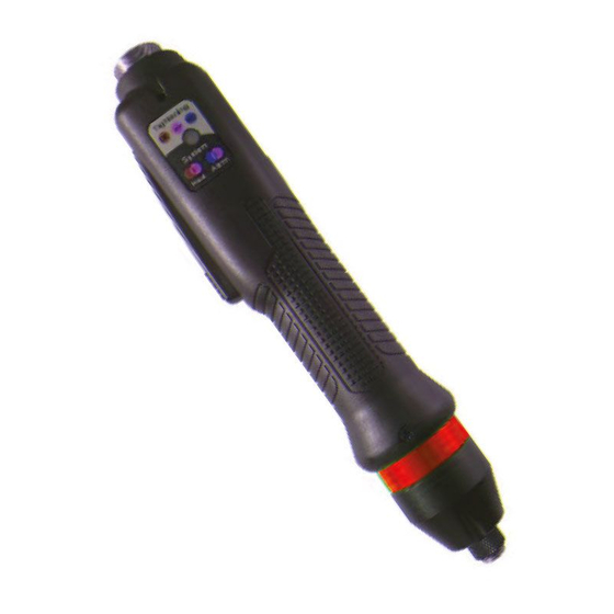
Page 7: Screwdriver
Instructions manual / MD Series Screwdriver General specification Item Specification Electric power DC38V, 5A max Motor Swiss DC servo motor Torque accuracy 10% in full scale Torque repeatability +/- 3% Auto speed by torque setting, Speed Model specification Gear ratio ( 1/16 ) – 1/1,1/2,1/4,1/11,1/16,1/36,1/64... - Page 8 Instructions manual / MD Series ● Pistol grip hand held (Trigger start) Model Torque(Nm) Speed range Bit socket Controller MDP3201 0.1 ~ 1.17 150-2000 Hex1/4” Hex1/4” MDP3202 0.2 ~ 2.15 150-2000 Hex1/4” MDP3204 0.4 ~ 3.9 150-1500 Hex1/4” MDC-32 MDP3211 1 ~ 8.8...
- Page 9 Instructions manual / MD Series ● Spindle for automation (Remote start by I/O) Model Torque(Nm) Speed range Bit socket Wight Controller 0.010 ~ 0.068 MDA2201 1000 dia.4 half moon 0.02 ~ 0.27 MDA2204 1000 dia.4 half moon 0.03 ~ 0.39...
-
Page 10: Auto Speed By Torque Setting Under The Each Test Condition
Instructions manual / MD Series Auto Speed by torque setting under the each test condition ◆ Speed range : Available setting range by manual ◆ Auto speed by torque setting : Safe speed not exceeding over torque by rotation inertia... - Page 11 Instructions manual / MD Series...
-
Page 12: Screwdriver Dimension
Instructions manual / MD Series Screwdriver dimension ■ MD2601, MD2602 Bit holder (Option) for Ohmi V-17 or equivalent ( Hex1/4” with Dia 7mm body hold by bearing ) Vacuum pick-up assy (Option) for Ohmi V-17 or equivalent ( Hex1/4” with Dia 7mm body hold by bearing ) Mouth piece is not included in the assy. - Page 13 Instructions manual / MD Series ■ MD2604, MD2611, MD2616 Bit holder (Option) for Ohmi V-17 or equivalent ( Hex1/4” with Dia 7mm body hold by bearing ) Vacuum pick-up assy (Option) for Ohmi V-17 or equivalent ( Hex1/4” with Dia 7mm body hold by bearing ) Mouth piece is not included in the assy.
- Page 14 Instructions manual / MD Series ■ MD3201, MD3202 Bit holder (Option) for Ohmi V-17 or equivalent ( Hex1/4” with Dia 7mm body hold by bearing ) Vacuum pick-up assy (Option) for Ohmi V-17 or equivalent ( Hex1/4” with Dia 7mm body hold by bearing ) Mouth piece is not included in the assy.
- Page 15 Instructions manual / MD Series ■ MD3204, MD3211, MD3216 Bit holder (Option) for Ohmi V-17 or equivalent ( Hex1/4” with Dia 7mm body hold by bearing ) Vacuum pick-up assy (Option) for Ohmi V-17 or equivalent ( Hex1/4” with Dia 7mm body hold by bearing ) Mouth piece is not included in the assy.
- Page 16 Instructions manual / MD Series ■ MD3236, MD3264...
- Page 17 Instructions manual / MD Series ■ MDH2604, MDH2611, MDH2616 Bit socket : 1/4” hex female (quick change) ■ MDH3201, MDH3204, MDH3211, MDH3216 Bit socket : 1/4” hex female (quick change) Bit socket : 3/8”SQ drive...
- Page 18 Instructions manual / MD Series ■ MDP3201, MDP3202, MDP3204, MDP3211, MDP3216 1/4” Hex female U : Top cable connection Ex. MDP3216-A/U D : Grip down cable connection Ex. MDP3216-A/D 3/8” SQ male Options Vacuum pick-up assy Bit socket type : A(1/4” Hex), 3/8”SQ Cable connection : U (top side), D (grip end) Bit holder for 1/4”...
- Page 19 Instructions manual / MD Series ■ MDA2201-E +VC M D A 2 2 0 1 - E + V C Model Bit type A:1/4”Hex E:Dia.4mm Option accessory V : Vacuum pick-up assy C : Bit Cushion Vacuum pick-up + Bit cushion (Option)
- Page 20 Instructions manual / MD Series ■ MDA2601 Options 1/4” Hex female Bit holder with bearing Vacuum pick-up assy Bit : 1/4” Hex Ohmi V-17 bit or equivalent...
- Page 21 Instructions manual / MD Series ■ MDA2604, MDA2611, MDA2616 Options Bit holder with bearing Vacuum pick-up assy Bit : 1/4” Hex Ohmi V-17 bit or equivalent 1/4” Hex female...
- Page 22 Instructions manual / MD Series ■ MDA2602, MDA3201, MDA3202 Options Bit holder with bearing Vacuum pick-up assy Bit : 1/4” Hex Ohmi V-17 bit or equivalent 1/4” Hex female...
- Page 23 Instructions manual / MD Series ■ MDA3204, MDA3211, MDA3216 Options Bit holder with bearing 1/4” Hex female Vacuum pick-up assy Bit : 1/4” Hex Ohmi V-17 bit or equivalent...
- Page 24 Instructions manual / MD Series ■ MDA3236, MDA3264...
-
Page 25: Controller
Instructions manual / MD Series Controller Specification Specification Item MDC-26 series MDC-32 series Input AC230V, 50/60Hz 2.5A Output DC 38V 5A Fuses 230V T5A Qty : 2x(N+L) Operating environment 0 ~ 40℃ / 15 ~ 80% RH ( without dew ) Front panel 4.3”... -
Page 26: Controller Dimension
Instructions manual / MD Series Controller dimension Option :Lift-up stand kit Memory card (option) Protected with a cover... -
Page 27: Operation
Instructions manual / MD Series Operation Getting started at first power on or after screwdriver change. It is really important to initialize the controller and driver as a set, before attempting to make any settings, as the information stored within the controller during testing at time of manufacture may not correlate with the driver shipped with the system. - Page 28 Instructions manual / MD Series • Click Controller. First parameter page is displayed • Click 2 times on arrow at bottom right side to go to Controller page 3/9 : • On last line ‘Controller parameter initialize’ , set value to 77 and valid.
- Page 29 Instructions manual / MD Series • During initialization, • After initialization, automaticaly go back to display...
-
Page 30: Operation Screen
Instructions manual / MD Series Operation screen Program(Preset) # (P1 – P15) or Multiseq. MA, MB or Model (M1 to M15) Fastening result OK/NG Menu Date & Time Torque target, Snug angle Speed target/Monitoring Count target/Monitoring Monitoring angle/time Monitoring torque Operation screen is a default window when the controller power ON. - Page 31 Instructions manual / MD Series Touch Screen field to move Preset # or Model Password Log In select Last count cancel Real time monitoring...
-
Page 32: Rapid View Parameter Screens
Instructions manual / MD Series Rapid view Parameter screens... - Page 33 Instructions manual / MD Series...
-
Page 34: Presets Or Model Select
Instructions manual / MD Series Presets or Model select To use Model, Controller 4/8 → Model select ON setting required There are 15 presets of program. Each preset contains the following parameters - - Torque - - Speed - - verifying angles - - soft start duration time - - free speed tightening. -
Page 35: Parameters
Instructions manual / MD Series Parameters To program each Presets, Click and go to Parameter menu require password to log in The initial factory setting is “ 0 “ for password The password can be changed once log in. There are approx.. 500 address for each parameters. -
Page 36: Fastening Settings
Instructions manual / MD Series Fastening settings Parameters listed on A, B and C pages for each Preset from 1 to 15 Preset selection Type Unit Range Initial Description Control type TC/AM : torque control/ angle monitoring AC/TM: angle control/ torque monitoring... - Page 37 Instructions manual / MD Series Target angle Unit Range Initial degree 0 ~ 9999 Description Target angle in AC/TM mode Min angle Unit Range Initial degree 0 ~ 9999 Description Minimum angle to be OK in TC/AM mode Max angle...
- Page 38 Instructions manual / MD Series Soft start Unit Range Initial msec 0 ~ 300 Description Speed reach to the target in the setting time, Preset complement to acceleration controller parameter Free angle Unit Range Initial degree 0 ~ 9999 Description...
-
Page 39: Advanced Functions
Instructions manual / MD Series Advanced functions: Free reverse rotation, Engaging torque détection, Angle after torque up 3 extra fonctions can be set and selected or not for each Preset ① ② ③ Fastening 6.7.1 Free reverse rotation before Fastening... -
Page 40: 6.7.2 Engaging Torque Detection
Instructions manual / MD Series 6.7.2 Engaging Torque detection It is possible only when the screw engaging provide significantly higher torque than previous free run. Enable preset number Unit Range Initial YES NO Description Enable this function Speed Unit Range... -
Page 41: 6.7.3 Angle After Torque Up
Instructions manual / MD Series 6.7.3 Angle after torque up It manage extra angle control in both forward or reverse direction after tightening by torque. Enable Unit Range Initial YES NO Description Enable this function Speed Unit Range Initial Tool range... -
Page 42: Multi Sequence Settings
Instructions manual / MD Series Multi Sequence settings Multi sequence provide a cycle of fastening by a start signal. Total 10 steps of programing is allowed in MA(Multi A) and MB(Multi B) presets To program, select the command and required parameter on each step. -
Page 43: Model Settings
Instructions manual / MD Series Model settings It provides sequential screw tightening with screw counting feature together with I/O and time delay managing by programing in 10 steps. There are 4 different type of command – Input, Output, Fastening and Time delay... - Page 44 Instructions manual / MD Series ◆ Command details Command Description Data 1 Data 2 0 : No output → NG 1 : Active High Input # select 2 : Active Low Input Mapping digital Input from 1 - 8 3 : High status 4 : Low status 0 : No Output →...
-
Page 45: Screw Count Settings
Instructions manual / MD Series Screw count settings Screw count parameters are set for presets and models. Sensor signal select : Count start(IN) / end(OUT) No signal, auto start (Auto) - auto reset to total number after “0” Sensor or switch with one trigger pulse - Count starts with only trigger pulse. - Page 46 Instructions manual / MD Series Port Count signal (OUT) : count complete signal can be set with 4 different type of signals Count complete(500ms) Torque up + Count complete Count complete(100ms) Screw missing alarm Count complete(500ms) : it provides 500ms of pulse type count complete signal after fasten all set numbers.
-
Page 47: Controller Settings
Instructions manual / MD Series Controller settings Forward run time Unit Range Initial 0 - 60 Run limit to forward rotation – It prevent the continuous running over the Description preset time. The driver stops automaticaly at the preset time and... - Page 48 Instructions manual / MD Series Acceleration Unit Range Initial 10 ~ 1000 Description Slow start of motor to the target speed. Fastening OK signal out time Unit Range Initial 0 ~ 500 Description Signal output time setting longer than 150ms which is factory setting.
- Page 49 Instructions manual / MD Series Torque calibration Unit Range Initial 90 ~ 110 Description It is the master calibration for whole range of tool. Saved in the tool memory and effective on another controller. The F/R switch should be at Reverse position before writing the new value.
- Page 50 Instructions manual / MD Series Model mode Unit Range Initial YES - NO Description Yes : model selection on operation screen No : Preset and Multi selection on operation screen Auto lock (model) Unit Range Initial YES - NO Description...
- Page 51 Instructions manual / MD Series Autospeed Unit Range Initial YES - NO Description Provide the safe speed on the torque setting (P1 ~ P15). The speed is automatically calculated Judge min turn Unit Range Initial turn 0 ~ 5 Description...
- Page 52 Instructions manual / MD Series Reverse lock Unit Range Initial YES - NO Description YES will disable the reverse rotation switch on screwdriver. Trigger start (handheld only) Unit Range Initial YES- NO Description Trigger ( ) start Enable/Disable with start lever...
- Page 53 Instructions manual / MD Series Alarm sound control Unit Range Initial YES NO Activation of noise alarm – stops when reset (timer or manual) Description Enable on panel Unit Range Initial YES- NO Description Enable touch screen field to move on operation screen(see page 29).
- Page 54 Instructions manual / MD Series Screw type Unit Range Initial CW - CCW Description Rotation direction for tightening Concern presets (P1 ~ P15). Auto data output port Unit Range Initial RS232 - Ethernet RS232 Description Data output port selection for automatic report...
- Page 55 Instructions manual / MD Series Torque holding time Unit Range Initial 1 ~ 20 Description Timelap torque is maintained after torque RS232 select Unit Range Initial MODBUS - Barcode MODBUS Description RS232 Port use : for data report or barcode reader...
-
Page 56: I/O Settings
Instructions manual / MD Series I/O settings... - Page 57 Instructions manual / MD Series MDC 25P I/O schematic The digital I/O provide the free assignment feature for 8 Inputs and 8 Outputs. Factory setting of I/O assignments are as following. To validate changing I/O, turn the power OFF and ON again.
- Page 58 Instructions manual / MD Series Binary coding with 5 inputs to select preset # and Mode (identical for Model) Input Torque select Torque select Torque select Torque select Multi Preset # sequence Multi A Multi B ◆ Binary coding with 3 outputs for error codes in 7 groups...
-
Page 59: Network Settings
Instructions manual / MD Series Network settings Initial : IP adress : 192 . 168 . 1 . 100 Gateway : if necessary Ethernet port : 5000 (0 ~ 9999) -
Page 60: Monitoring
Instructions manual / MD Series Monitoring To monitor fastening data and I/O status, Click and go to There are three(3) real-time monitoring menu. And one error history. Graph : torque, Angle, Speed and current I/O : Input & output status Network : RS-232 &... - Page 61 Instructions manual / MD Series ◆ I/O Status monitoring 48.5 The active I/O & tool operation signals are displayed with orange color by real time. The temperature of the motor surface is also displayed. Refer to the operation manual of ParaMon for details of wiring, schematic and digital I/O mapping.
-
Page 62: Remote & Auto Customizing
Instructions manual / MD Series Remote & Auto customizing For remote operation and Auto customizing parameters, Click , and ◆ Remote The tool and output signal can be operated remotely by click the screen. It is useful feature to simulate the tools in automation integration. Easy to find the output... - Page 63 Instructions manual / MD Series ◆ Auto customizing parameters 3257 120.5 1050 1050 2000 3057 Simulation & modification window MD tool has the auto speed setting feature against torque setting not to provide any over torque by speed shock. This auto speed is safe speed on the hard joint condition. On the real application, this setting can be changed manually.
-
Page 64: General Settings
Instructions manual / MD Series General Settings To modify Date, Time and backlight brightness , Click , and System date and time can be modified. yyyy-mm-dd hh:mm:ss Backlight brightness is adjustable between 2 to 64. Factory setting is 45. 2016-12-31 14:52:30... -
Page 65: Barcode Settings
Instructions manual / MD Series Barcode settings The barcode information can select the Preset or Model by the setting. In order to use barcode scanner, there are some parameters to be selected prior to the barcode setting. Controler 9/9 screen : R2232C : Modbus / Barcode (1) -
Page 66: Sd Memory Card (Option)
Instructions manual / MD Series SD memory card (Option) SD memory card specification SD card type Size Format Class 10 Max 8GB FAT32 To use this option, check on the parameter (A305) on the Parameter setting. System creates the folders of YEAR, MONTH automatically. And it creates one file in CSV format with the file name of DATE. -
Page 67: Modbus Com Protocol
Instructions manual / MD Series ** The last scanning data is recorded together with every fastening data MODBUS COM protocol MDC controller is capable of connecting to the host controller (Handy Loader, HMI, PLC, PC, etc.) through RS232 serial communication or Ethernet, allowing the user to use such functions as parameter change and data monitoring. -
Page 68: Torque Calibration And Compensation
Instructions manual / MD Series Torque calibration and compensation Torque calibration : It is the master calibration for whole range of tool, saved in the tool memory. The F/R switch should be at Reverse position before writing the new value. - Page 69 Instructions manual / MD Series Torque compensation : Individual torque tuning on each preset. Saved in the controller Torque compensation can be used when : The reading on the torque meter is variable according to the fastening condition on each preset, and it should be decreased or increased together on other presets, the torque compensation is useful in parameter setting of each preset.
-
Page 70: Error Code
Instructions manual / MD Series Error code System error How to code Error Description reset When the power of controller is ON, the tool offset is RESET 110 AD offset error out of range. button Reset and retry booting. If failed, repair is required... -
Page 71: Fastening Error By The Pattern Setting
Instructions manual / MD Series Fastening error by the pattern setting code Error Description How to reset Forward run time Over run time limit (Forward) contoller Auto reset after over page1/9 (A270 ParaMon) set time Reverse run time Auto reset after... - Page 72 Instructions manual / MD Series torque reached to the high limit of Auto reset after Over torque error torque set time Torque up in free Torque reach to the 110% of the target Auto reset after speed duration torque during free speed operation.
-
Page 73: Parameter Details And Factory Setting
Instructions manual / MD Series Parameter details and factory setting (Firmware version 1.06.1 ) Factory Preset # Parameter Address setting TC/AM (0) AC/TM (1) Target torque Max torque Auto Torque limit (%) Min torque No use Target angle(degree) Min angle(degree) 0-9999... - Page 74 Instructions manual / MD Series 0) None Parameter Factory 1) Preset select 1 Preset # Address 2) Preset select 2 setting 3) Preset select 3 Input #1 4) Preset select 4 5) Start Input #2 6) Fasten / Loosen 7) Driver Lock...
- Page 75 Instructions manual / MD Series Factory Preset # Parameter Address setting Run time limit / Forward (sec) Run time limit / Reverse (sec) Motor stall time limit (sec) Loosening speed (rpm) Auto Motor acceleration (ms) Fastening complete signal OUT time Setting 1 Driver ID no.
- Page 76 Instructions manual / MD Series Factory Preset # Parameter Address setting IP Address1 IP Address2 IP Address3 IP Address4 IP Address Gateway 1 Gateway 2 Gateway 3 Gateway 4 Port 5000 MS PG 1 MS PG 2 MS PG 3...
- Page 77 Instructions manual / MD Series Factory Preset # Parameter Address setting Controller model Auto 350 ~ Model Model data( 150 ) Firmware Auto Version ★ Please refer to the operation manual of ParaMon PC software for details of parameter settings.
- Page 78 Instructions manual / MD Series...
- Page 79 Instructions manual / MD Series...
Need help?
Do you have a question about the MD Series and is the answer not in the manual?
Questions and answers