Table of Contents
Advertisement
Harman Kardon
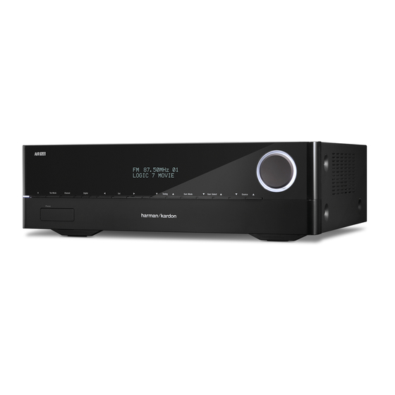
Avr 151/230
75W 5.1 CHANNEL A/V RECEIVER
REMOTE CONTROL FUNCTIONS
Released EU2013
CONTENTS
3
EXPLODED VIEW AND PARTS
5
PARTS LIST
7
BIAS ADJUSTMENT
9
SEMICONDUCTOR PINOUTS
10
PCB DRAWINGS
11
12
WIRING DIAGRAM
13
Harman Consumer Group, Inc.
8500 Balboa Boulevard
Northridge, California 91329
Service Manual
14
15
39
40
108
118
120
121
2, 03/2016
Rev
Advertisement
Table of Contents

Related Manuals for Harman Kardon AVR 151/230C


Summary of Contents for Harman Kardon AVR 151/230C
-
Page 1: Service Manual
Harman Kardon Service Manual AVR 151/230 75W 5.1 CHANNEL A/V RECEIVER CONTENTS FRONT PANEL CONTROLS EXPLODED VIEW AND PARTS REAR PANEL CONNECTORS PARTS LIST REMOTE CONTROL FUNCTIONS BIAS ADJUSTMENT PROCESSOR RESET SEMICONDUCTOR PINOUTS TROUBLESHOOTING PCB DRAWINGS SPECIFICATIONS BLOCK DIAGRAMS PACKAGE DRAWING... - Page 2 Harman Kardon AVR 151 Service Manual AVR 1510, AVR 151, AVR 151/230C Audio/video receiver DTS Logo DLNA Logo Owner’s Manual ® Page 2 of 131...
- Page 3 Harman Kardon AVR 151 Service Manual Front-Panel Controls Front-Panel Controls (AVR 1510)/ RDS 1510 Port Page 3 of 131...
- Page 4 Harman Kardon AVR 151 Service Manual Front-Panel Controls Front-Panel Controls, continued Front-panel display: Power indicator/Power button: Up/Down buttons/Tuning buttons: Surround Mode Category button: Audio Processing and Surround Sound, System Settings, Sleep Surround Mode Select buttons: II Movie mode to DTS ®...
- Page 5 Harman Kardon AVR 151 Service Manual Rear-Panel Connectors Rear-Panel Connectors Radio Antenna (AVR 1510) (AVR 151) Page 5 of 131...
- Page 6 Harman Kardon AVR 151 Service Manual Rear-Panel Connectors ® Rear-Panel Connectors, continued HDMI Input connectors: Digital Audio connectors: Connect Your Connect Your Audio and Video Source Devices, Audio and Video Source Devices, Radio Antenna connectors: AC Input connector (AVR 151 only):...
-
Page 7: System Remote Control Functions
Harman Kardon AVR 151 Service Manual System Remote Control Functions System Remote Control Functions Server Info/Option Tone TopMenu Page 7 of 131... - Page 8 Harman Kardon AVR 151 Service Manual System Remote Control Functions System Remote Control Functions, continued Clear button: Test Tone button: Program the Remote to Control Your Source Devices and TV Delay Adjust button: See Configure the AVR for Your Speakers,...
- Page 9 Software Update: If a software upgrade is released for your AVR, installation instructions will be available in the Product Support section of the Web site or from Harman Kardon customer service. At that time, you may use this submenu to install the upgrade software.
-
Page 10: Troubleshooting
Harman Kardon AVR 151 Service Manual Troubleshooting Symptom Cause Solution Page 10 of 131... -
Page 11: Specifications
Harman Kardon AVR 151 Service Manual Specifications Specifications AM Tuner Section Audio Section 38dB 500μV 30dB Video Section 100dB PAL (AVR 151) DTS: 55dB video): HDMI: General Specifications FM Tuner Section 70dB/68dB 70dB 80dB 80dB Page 11 of 131... - Page 12 Harman Kardon AVR 151 Service Manual AVR151/230 2. Package Drawing 1. Instruction manual ass'y - Accessories(CQXAVR151/230) MANUAL ASS'Y FM 1 POLE ANT(UL) POLY BAG AM LOOP ANTENNA ASS'Y BATTERY ASS'Y REMOCON SHEET,QUICK START GUIDE SHEET,SAFETY SNOW PAD (L) CORD , POWER(EUR)
- Page 13 Harman Kardon AVR 151 Service Manual DISASSEMBLY AVR151/230 1. Removing the Top Cabinet 3. Removing the Rear Panel Remove the Screws Remove the Screws 4. Removing the Main PCB Remove the Screws 2. Removing the Front Panel Remove the Screws...
- Page 14 Harman Kardon AVR 151 Service Manual C C T 4 B +1 J 40-2 D SC , Q, Q y t 40-1 , B V L CB 1 6 B65 6 B65 , R O CGL1 3 G 1 3...
- Page 15 Harman Kardon AVR 151 Service Manual AVR 151, 5.1CH RECEIVER, bill of materials Level Ref# Component Description Drawing No REQ-Qty CBN1A269B65 KNOB , VOLUME CGL1A300 INDICATOR , VOLUME CGR1A555B63 COVER , JACK AVR1510 CGWAVR151/230 FRONT PANEL ASS'Y ...3 CBT2A1064 KNOB , STANDBY ...3...
- Page 16 Harman Kardon AVR 151 Service Manual AVR 151, 5.1CH RECEIVER, bill of materials Level Ref# Component Description Drawing No REQ-Qty ...3 COP12502H AVR1510 FRONT PCB ASS'Y ..6 R101 CRJ10DJ221T RES, CHIP(1608/5%/220ohm) 00200-0101 ..6 R102 CRJ10DJ681T RES, CHIP(1608/5%/680ohm) 00200-0120 ..6 R104...
- Page 17 Harman Kardon AVR 151 Service Manual AVR 151, 5.1CH RECEIVER, bill of materials Level Ref# Component Description Drawing No REQ-Qty ...3 COP12502H AVR1510 FRONT PCB ASS'Y ..6 R923 CRJ10DJ152T RES, CHIP(1608/5%/1.5Kohm) 00200-0119 ..6 R924 CRJ10DJ152T RES, CHIP(1608/5%/1.5Kohm) 00200-0119 ..6 R925...
- Page 18 Harman Kardon AVR 151 Service Manual AVR 151, 5.1CH RECEIVER, bill of materials Level Ref# Component Description Drawing No REQ-Qty ...3 COP12502H AVR1510 FRONT PCB ASS'Y ..4 JK53 CJJ9X012Z JACK , USB (ANGLE TYPE) ..4 JK64 CJJ2E026Z JACK, PHONES(6.35mm,SILVER) PJ-612A-51 ..4...
- Page 19 Harman Kardon AVR 151 Service Manual AVR 151, 5.1CH RECEIVER, bill of materials Level Ref# Component Description Drawing No REQ-Qty ...3 COP12502H AVR1510 FRONT PCB ASS'Y ..7 C1140 CCUS1H103KC CAP, CHIP(1608, 50V/0.01uF) 1608 SIZE ..7 C1144 CCUS1H104KC CAP, CHIP(1608, 50V/0.1uF) ..7...
- Page 20 Harman Kardon AVR 151 Service Manual AVR 151, 5.1CH RECEIVER, bill of materials Level Ref# Component Description Drawing No REQ-Qty ...3 COP12502H AVR1510 FRONT PCB ASS'Y ..7 C1379 CCUS1H104KC CAP, CHIP(1608, 50V/0.1uF) ..7 C1382 CCUS1H104KC CAP, CHIP(1608, 50V/0.1uF) ..7 C1384 CCUS1H104KC CAP, CHIP(1608, 50V/0.1uF)
- Page 21 Harman Kardon AVR 151 Service Manual AVR 151, 5.1CH RECEIVER, bill of materials Level Ref# Component Description Drawing No REQ-Qty ...3 COP12502H AVR1510 FRONT PCB ASS'Y ..7 L1207 CLZ9Z014Z FERRITE CHIP BEAD(4516/60R) HCB4516KF-600T60 ..7 L1214 CLZ9Z014Z FERRITE CHIP BEAD(4516/60R) HCB4516KF-600T60 ..7...
- Page 22 Harman Kardon AVR 151 Service Manual AVR 151, 5.1CH RECEIVER, bill of materials Level Ref# Component Description Drawing No REQ-Qty ...3 COP12502H AVR1510 FRONT PCB ASS'Y ..7 R1254 CRJ10DJ0R0T RES, CHIP(1608/5%/0ohm) 00200-0090 ..7 R1255 CRJ10DJ0R0T RES, CHIP(1608/5%/0ohm) 00200-0090 ..7 R1258...
- Page 23 Harman Kardon AVR 151 Service Manual AVR 151, 5.1CH RECEIVER, bill of materials Level Ref# Component Description Drawing No REQ-Qty ...3 COP12502H AVR1510 FRONT PCB ASS'Y ..7 R1511 CRJ10DJ332T RES, CHIP(1608/5%/3.3Kohm) 00200-0105 ..7 R1512 CRJ10DJ152T RES, CHIP(1608/5%/1.5Kohm) 00200-0119 ..7 R1513 CRJ10DJ682T RES, CHIP(1608/5%/6.8Kohm)
- Page 24 Harman Kardon AVR 151 Service Manual AVR 151, 5.1CH RECEIVER, bill of materials Level Ref# Component Description Drawing No REQ-Qty ..7 C1129 CCUS0J225KC CAP, CHIP(1608, 6.3V/2.2uF) ..7 C1131 CCUC0J106KC CAP, CHIP(2012, 6.3V/10uF, X7R) LAO-63V103MS56PW# ..7 C1133 CCUS1H103KC CAP, CHIP(1608, 50V/0.01uF) 1608 SIZE ..7...
- Page 25 Harman Kardon AVR 151 Service Manual AVR 151, 5.1CH RECEIVER, bill of materials Level Ref# Component Description Drawing No REQ-Qty ..7 C1428 CCUC1A226KC CAP, CHIP(2012, 10V/22uF) ..7 C1429 CCUS1H104KC CAP, CHIP(1608, 50V/0.1uF) ..7 C1501 CCUS1H272KC CAP, CHIP(1608, 50V/2700pF) ..7 C1502...
- Page 26 Harman Kardon AVR 151 Service Manual AVR 151, 5.1CH RECEIVER, bill of materials Level Ref# Component Description Drawing No REQ-Qty ..7 L1202 CLZ9Z014Z FERRITE CHIP BEAD(4516/60R) HCB4516KF-600T60 ..7 L1203 CLZ9Z014Z FERRITE CHIP BEAD(4516/60R) HCB4516KF-600T60 ..7 L1206 CLZ9Z014Z FERRITE CHIP BEAD(4516/60R) HCB4516KF-600T60 ..7...
- Page 27 Harman Kardon AVR 151 Service Manual AVR 151, 5.1CH RECEIVER, bill of materials Level Ref# Component Description Drawing No REQ-Qty ..7 R1065 CRJ10DJ101T RES, CHIP(1608/5%/100ohm) 00200-0100 ..7 R1066 CRJ10DJ101T RES, CHIP(1608/5%/100ohm) 00200-0100 ..7 R1101 CRJ10DJ103T RES, CHIP(1608/5%/10Kohm) 00200-0096 ..7 R1102...
- Page 28 Harman Kardon AVR 151 Service Manual AVR 151, 5.1CH RECEIVER, bill of materials Level Ref# Component Description Drawing No REQ-Qty ..7 R1362 CRJ10DJ330T RES, CHIP(1608/5%/33ohm) 00200-0118 ..7 R1363 CRJ10DJ330T RES, CHIP(1608/5%/33ohm) 00200-0118 ..7 R1364 CRJ10DJ0R0T RES, CHIP(1608/5%/0ohm) 00200-0090 ..7 R1365...
- Page 29 Harman Kardon AVR 151 Service Manual AVR 151, 5.1CH RECEIVER, bill of materials Level Ref# Component Description Drawing No REQ-Qty ..6 C1709 CCUS1H220JA CAP, CHIP(1608, 50V/22pF) ..6 C1710 CCUS1H220JA CAP, CHIP(1608, 50V/22pF) ..6 C1711 CCUS1H220JA CAP, CHIP(1608, 50V/22pF) ..6 C1742 CCUS1H104KC CAP, CHIP(1608, 50V/0.1uF)
- Page 30 Harman Kardon AVR 151 Service Manual AVR 151, 5.1CH RECEIVER, bill of materials Level Ref# Component Description Drawing No REQ-Qty ..6 R1827 CRJ10DJ104T RES, CHIP(1608/5%/100Kohm) 00200-0097 ..6 R1828 CRJ10DJ104T RES, CHIP(1608/5%/100Kohm) 00200-0097 ..6 R1829 CRJ10DJ104T RES, CHIP(1608/5%/100Kohm) 00200-0097 ..6 R1836 CRJ10DJ472T RES, CHIP(1608/5%/4.7Kohm)
- Page 31 Harman Kardon AVR 151 Service Manual AVR 151, 5.1CH RECEIVER, bill of materials Level Ref# Component Description Drawing No REQ-Qty ..5 C633 CCEA1HH470TC CAP , ELECT (50V/47uF) ..5 C634 CCEA1HH470TC CAP , ELECT (50V/47uF) ..5 C636 CCEA1HH470TC CAP , ELECT (50V/47uF) ..5...
- Page 32 Harman Kardon AVR 151 Service Manual AVR 151, 5.1CH RECEIVER, bill of materials Level Ref# Component Description Drawing No REQ-Qty ..5 R508 CRD20TJ273T RES, CARBON(1/5W,27Kohm,J) ..5 R509 CRD20TJ273T RES, CARBON(1/5W,27Kohm,J) ..5 R511 CRD20TJ152T RES, CARBON(1/5W,1.5Kohm,J) ..5 R512 CRD20TJ152T RES, CARBON(1/5W,1.5Kohm,J) ..5...
- Page 33 Harman Kardon AVR 151 Service Manual AVR 151, 5.1CH RECEIVER, bill of materials Level Ref# Component Description Drawing No REQ-Qty ..5 R671 CRD20TJ472T RES, CARBON(1/5W,4.7Kohm,J) ..5 R672 CRD20TJ472T RES, CARBON(1/5W,4.7Kohm,J) ..5 R673 CRD20TJ472T RES, CARBON(1/5W,4.7Kohm,J) ..5 R674 CRD20TJ472T RES, CARBON(1/5W,4.7Kohm,J) ..5...
- Page 34 Harman Kardon AVR 151 Service Manual AVR 151, 5.1CH RECEIVER, bill of materials Level Ref# Component Description Drawing No REQ-Qty ..5 R942 CRD20TJ103T RES, CARBON(1/5W,10Kohm,J) ..5 R944 CRD20TJ103T RES, CARBON(1/5W,10Kohm,J) ..5 R946 CRD20TJ103T RES, CARBON(1/5W,10Kohm,J) ..5 R947 CRD20TJ103T RES, CARBON(1/5W,10Kohm,J) ..5...
- Page 35 Harman Kardon AVR 151 Service Manual AVR 151, 5.1CH RECEIVER, bill of materials Level Ref# Component Description Drawing No REQ-Qty ..6 C919 CCUP3A470JA CAP, CHIP(3216, 1KV/47pF, X7R) ..6 C923 CCUC1H104KC CAP, CHIP(2012, 50V/0.1uF) ..6 C924 CCUC1H222KC CAP, CHIP(2012, 50V/2200pF) ..6...
- Page 36 Harman Kardon AVR 151 Service Manual AVR 151, 5.1CH RECEIVER, bill of materials Level Ref# Component Description Drawing No REQ-Qty ..6 R936 CRJ18AJ102T RES, CHIP(2012/5%/1Kohm) 0805 5% ..6 R937 CRJ18AJ102T RES, CHIP(2012/5%/1Kohm) 0805 5% ..6 R938 CRJ18AJ561T RES, CHIP(2012/5%/560ohm) 0805 5% ..6...
- Page 37 Harman Kardon AVR 151 Service Manual AVR 151, 5.1CH RECEIVER, bill of materials Level Ref# Component Description Drawing No REQ-Qty ..4 CN20 CJP03GA90ZY WAFER,YW396-03B(3.96mm) ..4 CN66 CJP07GI236ZW LOCKING TYPE , STRAIGHT WAFER , 2MM A2008WV0-7P ..4 CN90 CJP02KA060ZY WAFER, 2P, 3.96mm ..4...
- Page 38 Harman Kardon AVR 151 Service Manual AVR 151, 5.1CH RECEIVER, bill of materials Level Ref# Component Description Drawing No REQ-Qty ...3 WF1501 CWC4C4A27B150B10 CARD , CABLE (27p,1.25mm Pitch, 150mm) ...3 WF1502 CWC4C4A17B120B10 CABLE , CARD(17P, 120MM, 1.25MM) CHE154 CLAMPER , ARM 0.12...
- Page 39 Harman Kardon AVR 151 Service Manual Page 39 of 131...
- Page 40 Harman Kardon AVR 151 Service Manual Page 40 of 131...
- Page 41 Harman Kardon AVR 151 Service Manual Page 41 of 131...
- Page 42 Harman Kardon AVR 151 Service Manual ISAHAYA ELECTRONICS CORPORATION Page 42 of 131...
- Page 43 Harman Kardon AVR 151 Service Manual 〈 Transistor〉 R T 1 N 1 4 4 X SERIES Transistor With Resistor For Switching Application Silicon NPN Epitaxial Type DESCRIPTION OUTLINE DRAWING UNIT: mm RT1N144X is a one chip transistor RT1N144U RT1N144C with built-in bias resistor,PNP type is RT1P144X.
- Page 44 Harman Kardon AVR 151 Service Manual 〈 Transistor〉 R T 1 N 1 4 4 X SERIES Transistor With Resistor For Switching Application Silicon NPN Epitaxial Type MAXIMUM RATING (Ta=25℃) RATING SYMBOL PARAMETER UNIT RT1N144T2 RT1N144U RT1N144M RT1N144C RT1N144S V...
- Page 45 Harman Kardon AVR 151 Service Manual 〈 Transistor〉 R T 1 N 1 4 4 X SERIES Transistor With Resistor For Switching Application Silicon NPN Epitaxial Type DC FORWARD CURRENT GAIN COMMON EMITTER OUTPUT VS COLLECTOR CURRENT 1000 VCE=5V Ta=25℃...
- Page 46 Harman Kardon AVR 151 Service Manual ISAHAYA ELECTRONICS CORPORATION Page 46 of 131...
- Page 47 Harman Kardon AVR 151 Service Manual LM7900 Imagis Co., Ltd. 1. Overview Description LM7900 series of fixed output negative voltage regulators are intended as complement to LM7800 series devices. These negative regulators are available in the same even-voltage options as the LM7800 devices Features •...
- Page 48 Harman Kardon AVR 151 Service Manual LM7800 Imagis Co., Ltd. 1. Overview Description The voltage regulators are designed as fixed-voltage regulator for a wide variety of applications Including local,on-card regulation. Although designed primarily as a fixed voltage regulator, these devices can be used with external components to obtain adjustable voltages and currents Features •...
- Page 49 Harman Kardon AVR 151 Service Manual Page 49 of 131...
- Page 50 Harman Kardon AVR 151 Service Manual Page 50 of 131...
- Page 51 Harman Kardon AVR 151 Service Manual Page 51 of 131...
- Page 52 Harman Kardon AVR 151 Service Manual ISL54220 Pin Configurations ISL54220 ISL54220 (10 LD 3.0X3.0 TDFN) (10 LD MSOP) TOP VIEW TOP VIEW LOGIC LOGIC CONTROL CONTROL HSD1+ HSD1+ HSD2+ HSD1- HSD2+ HSD1- HSD2- HSD2- ISL54220 (10 LD 1.8X1.4 μTQFN) TOP VIEW...
- Page 53 Harman Kardon AVR 151 Service Manual ESMT/EMP EML3418 Connection Diagram Order information TDFN-8 Package EML3418-00FF08NRR Adj Operation FF08 TDFN-8 Package RoHS & Halogen Free Rating: -40 to 85°C Package in Tape & Reel EML3418-00SE08GRR/NRR SOP-8FD Package Adj Operation SE08 SOP-8FD package RoHS (Pb Free) Rating: -40 to 85°C...
- Page 54 Harman Kardon AVR 151 Service Manual ESMT/EMP EML3418 Package Configuration SOP-8 Adjustable Pin Functions Pin # Pin Name Function Feedback Pin. Receives the feedback voltage from an external (Adjustable) resistive divider across the output. Output Voltage Pin. An internal resistive divider divides the output (Fixed voltage down for comparison to the internal reference voltage.
- Page 55 Harman Kardon AVR 151 Service Manual DB1514A 1.5A, Low Dropout Regulator with Power Good DESCRIPTION FEATURES The DB1514A is a very low dropout voltage linear Input Voltage Range: 2.5V to 6.0V regulator which can operate from the input Low Quiescent Current: Typ. 300uA @ voltages as low as 2.5V and is capable of...
- Page 56 Harman Kardon AVR 151 Service Manual DB1514A PIN DESCRIPTION PIN NO SYMBOL DESCRIPTION 8-TDFN 8-SOP-EP Open Drain Power-Good (PG) Output. Enable Input. Input Supply Voltage Pin. Output pin Feedback Pin. Connect to output through a voltage-divider to set the output. Recommended that the tolerance of feedback resistors is below 1%.
- Page 57 Harman Kardon AVR 151 Service Manual DB1510B PIN DESCRIPTION PIN NO SYMBOL DESCRIPTION TO-252 (I) TO-252 (II) 8-TDFN SOT-223 (I) SOT-223 (II) Input Voltage 2, TAB Ground 2, TAB 5, 6 Output Voltage 2, 4, 7, 8 No Connection PIN CONFIGURATION...
- Page 58 Harman Kardon AVR 151 Service Manual DB1230 3A, 700KHz, Synchronous Step-down Converter DESCRIPTION FEATURES The DB1230 is a high frequency synchronous 4.5V to 16V operating input range. rectified step-down regulator which integrates an High-side 110 m , low-side 85 m...
- Page 59 Harman Kardon AVR 151 Service Manual DB1230 PIN DESCRIPTION PIN NO. SYMBOL DESCRIPTION Enable pin. For automatic start-up, please leave it open and in case of on/off control, there should be pull-down resistor.(10K~100Kohm) Feedback pin. External resistors are connected between OUT and GND to set the regulated output voltage based on 0.8V reference.
- Page 60 Harman Kardon AVR 151 Service Manual DB1230 PIN DESCRIPTION PIN NO. SYMBOL DESCRIPTION No Connection pin. Feedback pin. External resistors are connected between OUT and GND to set the regulated output voltage based on 0.8V reference. Internal regulated output. A decoupling capacitor should be close to this pin as possible External soft-start program pin.
- Page 61 Harman Kardon AVR 151 Service Manual Page 61 of 131...
- Page 62 Harman Kardon AVR 151 Service Manual Page 62 of 131...
- Page 63 Harman Kardon AVR 151 Service Manual CAT803, CAT809, CAT810 3-Pin Microprocessor Power Supply Supervisors Description The CAT803, CAT809, and CAT810 are supervisory circuits that monitor power supplies in digital systems. The CAT803, CAT809, and http://onsemi.com CAT810 are direct replacements for the MAX803, MAX809 and MAX810 in applications operating over the industrial temperature range.
- Page 64 Harman Kardon AVR 151 Service Manual CAT803, CAT809, CAT810 Table 1. THRESHOLD SUFFIX SELECTOR Nominal Threshold Voltage Threshold Suffix Designation 4.63 V 4.55 V 4.38 V 4.00 V 3.08 V 2.93 V 2.63 V 2.32 V 1.60 V Table 2. PIN DESCRIPTIONS...
- Page 65 Harman Kardon AVR 151 Service Manual Data Sheet 600mA LOW DROPOUT LINEAR REGULATOR 600mA LOW DROPOUT LINEAR REGULATOR AP1117M AP2317 LOW DROPOUT LINEAR REGULATOR AZ1117C General Description Features The AZ1117C is a low dropout three-terminal regula- Current Limit: 1.0A (Typ.) tor.
- Page 66 Harman Kardon AVR 151 Service Manual Data Sheet 600mA LOW DROPOUT LINEAR REGULATOR 600mA LOW DROPOUT LINEAR REGULATOR AP1117M AP2317 LOW DROPOUT LINEAR REGULATOR AZ1117C Pin Configuration D Package (TO-252-2 (2)) (TO-252-2 (1)) INPUT INPUT OUTPUT OUTPUT ADJ/GND ADJ/GND (TO-252-2 (3))
- Page 67 Harman Kardon AVR 151 Service Manual Data Sheet 600mA LOW DROPOUT LINEAR REGULATOR 600mA LOW DROPOUT LINEAR REGULATOR AP1117M AP2317 LOW DROPOUT LINEAR REGULATOR AZ1117C General Description Features The AZ1117C is a low dropout three-terminal regula- Current Limit: 1.0A (Typ.) tor.
- Page 68 Harman Kardon AVR 151 Service Manual Data Sheet 600mA LOW DROPOUT LINEAR REGULATOR 600mA LOW DROPOUT LINEAR REGULATOR AP1117M AP2317 LOW DROPOUT LINEAR REGULATOR AZ1117C Pin Configuration D Package (TO-252-2 (2)) (TO-252-2 (1)) INPUT INPUT OUTPUT OUTPUT ADJ/GND ADJ/GND (TO-252-2 (3))
- Page 69 Harman Kardon AVR 151 Service Manual Description The Atmel AT45DB321D is a 2.5V or 2.7V, serial interface, sequential access flash memory ideally suited for a wide variety of digital voice-, image-, program code-, and data-storage applications. The AT45DB321D supports the Atmel RapidS serial interface for applications requiring very high speed operations.
- Page 70 Harman Kardon AVR 151 Service Manual Table 1-1. Pin Configurations Asserted Symbol Name and Function State Type Chip Select: Asserting the CS pin selects the device. When the CS pin is deasserted, the Input device will be deselected and normally be placed in the standby mode (not deep power- down mode), and the output pin (SO) will be in a high-impedance state.
- Page 71 Harman Kardon AVR 151 Service Manual ADI Confidential ADV7623 PIN CONFIGURATION AND FUNCTION DESCRIPTIONS DDCC_SCL DDCA_SDA PIN 1 CVDD RTERM CGND 5V_DETA RXC_C– HP_CTRLA RXC_C+ PGND TVDD PVDD RXC_0– XTAL1 RXC_0+ XTAL CGND PVDD RXC_1– PGND RXC_1+ PWRDN TVDD RESET RXC_2–...
- Page 72 Harman Kardon AVR 151 Service Manual ADV7623 ADI Confidential Pin No. Mnemonic Type Description RXC_2− HDMI input Digital Input Channel 2 Complement of Port C in the HDMI Interface. RXC_2+ HDMI input Digital Input Channel 2 True of Port C in the HDMI Interface.
- Page 73 Harman Kardon AVR 151 Service Manual ADI Confidential ADV7623 Pin No. Mnemonic Type Description TX2− HDMI output Differential Output Channel 2 Complement. Differential output of the red data at 10× the pixel clock rate; supports TMDS logic level. TX2+ HDMI output Differential Output Channel 2 True.
- Page 74 Harman Kardon AVR 151 Service Manual ADV7623 ADI Confidential Pin No. Mnemonic Type Description PGND Ground PVDD Ground. PVDD Power PLL Supply Voltage (1.8 V). XTAL Miscellaneous Input pin for 28.63636 MHz crystal or an external 1.8 V 28.63636 MHz clock oscillator source to analog clock the ADV7623.
- Page 75 Harman Kardon AVR 151 Service Manual Page 75 of 131...
- Page 76 Harman Kardon AVR 151 Service Manual Page 76 of 131...
- Page 77 Harman Kardon AVR 151 Service Manual STM32F205xx, STM32F207xx Pinouts and pin description Figure 12. STM32F20x LQFP144 pinout 1. RFU means “reserved for future use”. Doc ID 15818 Rev 5 35/147 Page 77 of 131...
- Page 78 Harman Kardon AVR 151 Service Manual Pinouts and pin description STM32F205xx, STM32F207xx Table 5. STM32F20x pin and ball definitions Pins Main Other Pin name function Alternate functions functions (after reset) TRACECLK/ FSMC_A23 / I/O FT ETH_MII_TXD3 I/O FT TRACED0/FSMC_A19 TRACED1/FSMC_A20 /...
- Page 79 Harman Kardon AVR 151 Service Manual STM32F205xx, STM32F207xx Pinouts and pin description Table 5. STM32F20x pin and ball definitions (continued) Pins Main Other Pin name function Alternate functions functions (after reset) 22 28 PF10 I/O FT PF10 FSMC_INTR ADC3_IN8 E9 12 23 29 G1...
- Page 80 Harman Kardon AVR 151 Service Manual Pinouts and pin description STM32F205xx, STM32F207xx Table 5. STM32F20x pin and ball definitions (continued) Pins Main Other Pin name function Alternate functions functions (after reset) USART2_RX/TIM5_CH4 / TIM9_CH2 / TIM2_CH4 / 17 G7 26 37 47 R2...
- Page 81 Harman Kardon AVR 151 Service Manual STM32F205xx, STM32F207xx Pinouts and pin description Table 5. STM32F20x pin and ball definitions (continued) Pins Main Other Pin name function Alternate functions functions (after reset) 51 61 M8 SS_6 SS_6 52 62 N8 DD_6...
- Page 82 Harman Kardon AVR 151 Service Manual Pinouts and pin description STM32F205xx, STM32F207xx Table 5. STM32F20x pin and ball definitions (continued) Pins Main Other Pin name function Alternate functions functions (after reset) I2C3_SMBA / TIM12_CH2/ 86 M13 I/O FT DCMI_D0 TIM5_CH1_ETR /...
- Page 83 Harman Kardon AVR 151 Service Manual STM32F205xx, STM32F207xx Pinouts and pin description Table 5. STM32F20x pin and ball definitions (continued) Pins Main Other Pin name function Alternate functions functions (after reset) 61 85 104 M14 PD14 I/O FT PD14 FSMC_D0/TIM4_CH3...
- Page 84 Harman Kardon AVR 151 Service Manual Pinouts and pin description STM32F205xx, STM32F207xx Table 5. STM32F20x pin and ball definitions (continued) Pins Main Other Pin name function Alternate functions functions (after reset) USART1_RTS / CAN1_TX/ 45 C1 71 104 123 B15...
- Page 85 Harman Kardon AVR 151 Service Manual STM32F205xx, STM32F207xx Pinouts and pin description Table 5. STM32F20x pin and ball definitions (continued) Pins Main Other Pin name function Alternate functions functions (after reset) TIM3_ETR/UART5_RX 54 C7 83 116 144 D12 I/O FT...
- Page 86 Harman Kardon AVR 151 Service Manual Pinouts and pin description STM32F205xx, STM32F207xx Table 5. STM32F20x pin and ball definitions (continued) Pins Main Other Pin name function Alternate functions functions (after reset) I2C1_SMBA/ CAN2_RX / OTG_HS_ULPI_D7 / 57 A5 91 135 163 A6...
-
Page 87: Device Information
Harman Kardon AVR 151 Service Manual PCM5100, PCM5101, PCM5102 SLAS764 MAY 2011 www.ti.com DEVICE INFORMATION TERMINAL FUNCTIONS, PCM510x PCM510X (top view) Table 2. TERMINAL FUNCTIONS, PCM510x TERMINAL DESCRIPTION NAME CPVDD Charge pump power supply, 3.3V CAPP Charge pump flying capacitor terminal for positive rail... - Page 88 Harman Kardon AVR 151 Service Manual tenatative NJM8080 DUAL OPERATIONAL AMPLIFIER GENERAL DESCRIPTION PACKAGE OUTLINE NJM8080 is the dual operational amplifier, specially designed for improving the tone control, which is most suitable for the audio application. Featuring noiseless, higher gain bandwidth, high output current and...
- Page 89 Harman Kardon AVR 151 Service Manual Page 89 of 131...
- Page 90 Harman Kardon AVR 151 Service Manual NJM2845/46 LOW DROPOUT VOLTAGE REGULATOR GENERAL DESCRIPTION PACKAGE OUTLINE The NJM2845 is low dropout voltage regulator. Advanced Bipolar technology achieves low noise, high ripple rejection and low quiescent current. NJM2845 is 3 terminal type and NJM2846 is ON/OFF control...
- Page 91 Harman Kardon AVR 151 Service Manual Page 91 of 131...
- Page 92 Harman Kardon AVR 151 Service Manual Page 92 of 131...
- Page 93 Harman Kardon AVR 151 Service Manual MX25L8005 • WP# pin Hardware write protection • HOLD# pin pause the chip without diselecting the chip • PACKAGE 8-pin SOP (150mil) 8-pin SOP (200mil) - 8-pin PDIP (300mil) - 8-land SON/WSON (6x5mm), 8-land SON is not recommended for new design...
-
Page 94: Absolute Maximum Ratings
Harman Kardon AVR 151 Service Manual ML61 ML61 Series Positive Voltage Detector Application Features Memory Battery Back-up Circuits CMOS Low Power Consumption : Typical 1.0uA at Microprocessor Reset Circuitry Vin=2.0V Power Failure Detection Selectable Detect V oltage : 1.1V to 6.0V in 0.1V increments Power-on Reset Circuit Highly Accurate : Detect V oltage 1.1V to 1.9V + 3%... - Page 95 Harman Kardon AVR 151 Service Manual ML61 Pin Configuration SOT-89 Pin Number Pin Name Description VOUT Supply Voltage Output Supply Voltage Input Ground Page 95 of 131...
- Page 96 Harman Kardon AVR 151 Service Manual ML61 Ordering Information Designator Description Output Configuration C = CMOS Output N = N-Channel Output Detect Voltage 30=3.0V 50=5.0V Detect Voltage Accuracy 2 = +2.0% 3 = +3.0% Package Type M = SOT-23 P = SOT-89...
- Page 97 Harman Kardon AVR 151 Service Manual ML61 Packaging Information (0.8) SOT-89 : 4.5 0.1 -0.1 0.15 SOT-23 : -0.05 -0.1 1.72 -0.05 0 ~ 0.1 (0.95) 0.42 0.06 0.42 0.06 0.04 0.49 0.06 1.27 1.27 TO-92 : 5.2 max Units : mm...
- Page 98 Harman Kardon AVR 151 Service Manual Page 98 of 131...
- Page 99 Harman Kardon AVR 151 Service Manual M24C64-W M24C64-R M24C64-F M24C32-W M24C32-R M24C32-F 64 Kbit and 32 Kbit Serial I²C bus EEPROM Feature summary ■ Two-Wire I C serial interface Supports 400kHz Protocol ■ Single supply voltage: – 2.5 to 5.5V for M24Cxx-W –...
- Page 100 Harman Kardon AVR 151 Service Manual Summary description M24Cxx-W, M24Cxx-R, M24Cxx-F Summary description These I C-compatible electrically erasable programmable memory (EEPROM) devices are organized as 8192 × 8 bits (M24C64-x) and 4096 × 8 bits (M24C32-x). Figure 1. Logic diagram...
- Page 101 Harman Kardon AVR 151 Service Manual M24Cxx-W, M24Cxx-R, M24Cxx-F Summary description Figure 2. DIP, SO, TSSOP and UFDFPN connections M24C64-x M24C32-x V CC V SS AI01845d 1. See Package mechanical section for package dimensions, and how to identify pin-1. 7/34...
- Page 102 Harman Kardon AVR 151 Service Manual Signal description M24Cxx-W, M24Cxx-R, M24Cxx-F Signal description 2.0.1 Serial Clock (SCL) This input signal is used to strobe all data in and out of the device. In applications where this signal is used by slave devices to synchronize the bus to a slower clock, the bus master...
- Page 103 Harman Kardon AVR 151 Service Manual M24Cxx-W, M24Cxx-R, M24Cxx-F Signal description Supply voltage (V 2.3.1 Operating supply voltage V Prior to selecting the memory and issuing instructions to it, a valid and stable V voltage within the specified [V (min), V...
- Page 104 Harman Kardon AVR 151 Service Manual Signal description M24Cxx-W, M24Cxx-R, M24Cxx-F Figure 5. C bus protocol START STOP Input Change Condition Condition START Condition STOP Condition AI00792B Table 2. Device select code Device Type Identifier Chip Enable Address Device Select Code 1.
- Page 105 Harman Kardon AVR 151 Service Manual ESMT M12L16161A (2Q) (Preliminary) SDRAM 512K x 16Bit x 2Banks Synchronous DRAM FEATURES GENERAL DESCRIPTION The M12L16161A is 16,777,216 bits synchronous high data JEDEC standard 3.3V power supply rate Dynamic RAM organized as 2 x 524,288 words by 16 bits,...
- Page 106 Harman Kardon AVR 151 Service Manual Page 106 of 131...
- Page 107 Harman Kardon AVR 151 Service Manual Page 107 of 131...
- Page 108 Harman Kardon AVR 151 Service Manual Page 108 of 131...
- Page 109 Harman Kardon AVR 151 Service Manual Page 109 of 131...
- Page 110 Harman Kardon AVR 151 Service Manual Page 110 of 131...
- Page 111 Harman Kardon AVR 151 Service Manual Page 111 of 131...
- Page 112 Harman Kardon AVR 151 Service Manual Page 112 of 131...
- Page 113 Harman Kardon AVR 151 Service Manual Page 113 of 131...
- Page 114 Harman Kardon AVR 151 Service Manual Page 114 of 131...
- Page 115 Harman Kardon AVR 151 Service Manual Page 115 of 131...
- Page 116 Harman Kardon AVR 151 Service Manual Page 116 of 131...
- Page 117 Harman Kardon AVR 151 Service Manual Page 117 of 131...
- Page 118 Harman Kardon AVR 151 Service Manual ADV7623 ADV7623 o k t p XVYVZV[ HDMI HDMI Repeater Repeater p Yj G G Audio Out Audio Out RJ 45 Milan Milan FS1230A FS1230A | ziG XU W UART APPLE PCM5100PWR PCM5100PWR Auth iC...
- Page 119 Harman Kardon AVR 151 Service Manual To HDMI / BCO SPDIF & Analog Audio I2S I/F By Upgrade UART UART & GPIO DAI 1 DA0 2 CS497024 CS497024 UART GPIO DAI 2 k zwG j Main MCU Main MCU IR In X 1...
- Page 120 Harman Kardon AVR 151 Service Manual †⁄›⁄'¢{ ⁄ ¢› ¤ { ⁄ ' « “ † › { “ › { fl · « ⁄ ¢ ⁄ fl § { – { { ⁄ { › ¨ ˚ … ‰ ˙...
- Page 121 Harman Kardon AVR 151 Service Manual Page 121 of 131...
- Page 122 Harman Kardon AVR 151 Service Manual Page 122 of 131...
- Page 123 Harman Kardon AVR 151 Service Manual AVR1X10/AVR1X1 SMPS SCHEMATIC DIAGRAM HS92 D942 R997 R999 R963 TF93 EER424220 HEAT SINK Division : C928, C936 Division : C937, C939 J901 J902 FCU20A40 (400V/20A) 1710, 171 : 63V 2200uF 1710, 171 : 63V 470uF...
- Page 124 Harman Kardon AVR 151 Service Manual › › fi ⁄¢ fi ⁄¢ ” « ›“ fl fl † † ‹ ‹ fi fi ¥ ¥ › · ‹ ¥ ƒ ” · ‹ fi ⁄¢ › ‹ › ‹ ·...
- Page 125 Harman Kardon AVR 151 Service Manual † – — ¡ – — ¡ ƒ R1793 HPL-OUT L-OUT › R1790 VOL-L ¥ ¥ FUNC_MUTE – FUNC_MUTE NJM2068MDTE1 › ƒ › ƒ – — ¡ – — ¡ ¥ ƒ ¥ §...
- Page 126 Harman Kardon AVR 151 Service Manual +1.8V_ADV7623 +3.3V_ADV7623 TVDD_3V3 TXAVDD_1V8 CVDD_1V8 PVDD_1V8 L1007 L1001 L1005 L1003 HCB1608KF-600T30 HCB1608KF-600T30 HCB1608KF-600T30 HCB1608KF-600T30 Q1001 DVDDIO_3V3 DVDDIO_3V3 DVDDIO_3V3 Q1002 HDMI1_RX_HPD T1P141C R1003 INT_TX_IN 0ohm R1038 HDMI_INT_TX T1N241C R1005 INT2 R1039 0ohm 22Kohm HDMI_INT_RX2 HDMI1_RX_PWR...
- Page 127 Harman Kardon AVR 151 Service Manual USB Switch Part NET_3.3V NET_3.3V USB_ OE L1109 L1110 USB_SEL MCU_USB_DM NET_3.3V MCU_USB_DP CHGND CHGND R1101 L1108 CHGND CHGND C1101 NET_1.2V 10V/22uF C1102 CHGND CHGND L1107 L1111 0.01uF NET_3.3V IC1101 NET_3.3V CVIISL54220IUZ-T L1106 NET_1.2V...
- Page 128 Harman Kardon AVR 151 Service Manual L1203 HDMI Power Supply CLZ9Z014Z FROM SMPS L1204 CLZ9Z014Z 2012.03.01 L1205 R1205 CLZ9Z014Z 350mA R1206 L1210 C1213 +3.3V_COM POWER_DOWN R1207 CLZ9R005Z POWER_DOWN R1208 0.01uF AMP_VCC_ON AMP_VCC_CONT ST+5V R1250 L1206 POWER_HI POWER_HIGH R1260 450mA CLZ9Z014Z...
- Page 129 Harman Kardon AVR 151 Service Manual R1301 C1301 100P R1302 +3.3V_DC +1V8 +3.3V_DC 4.7K AGND IC1309 CVINJM2845DL118 IC1307 NJM2115 L1302 L1303 L1301 CLZ9Z014Z CLZ9Z014Z +3V3 CLZ9Z014Z R1303 2.7K AGND R1305 C1304 R1306 C1305 R1307 AD_LIN 2.7K 150P C1306 10/16V 10/16V...
- Page 130 Harman Kardon AVR 151 Service Manual +3.3VC HDMI CEC_PART +3.3VC RESET JTAG_JTDO +3.3VC ST+5V JTAG_JTCLK JTAG_JTMS JTAG_JTDI IC1403 CVIDB1510BT3TR33 JTAG_TRST L1401 R1481 2012.03.27_NC = * CLZ9R005Z R1662 1 æ 8 „ CHGND CRJ10DJ0R0T CHGND R1401 MCU_ADV7623_CEC * Region Option R1474...
- Page 131 SCHEMATIC DIAGRAM Harman Kardon AVR 151 Service Manual +12V DC PROTECTOR Q1511 R940=1.5K R1571 12.12.17 RT1P144 Operating: +5.0V~ , -5.0V~ CURRENT_DET OC_DETECT R1580 POWER_MUTE POWER_FAIL * 3 Step Detect * MMBT5551 MMBT5551 DC_PROTECT R1506 R1504 Q1513 Q1514 3.8A : VCC 45V->41V OVERLOAD 4.3A : VCC 41V->25V...