Advertisement
Quick Links
Advertisement

Related Manuals for PeakTech 1235


Summary of Contents for PeakTech 1235
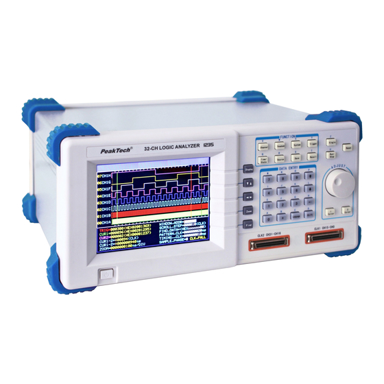
- Page 1 ® PeakTech 1235 Operation manual 32-Chanel Logic Analyser...
-
Page 2: Brief Introduction
So a popular logic analyzer with basic necessary function, simple operation and appropriate price must be selected. ® PeakTech 1235 Logic Analyzer is such a practical measuring instrument meeting the above requirements in data field. 2. Prepare for use 2.1. Check up Open the packing case and check whether the appearance of the instrument is intact, accessories are all there. - Page 3 2.2. Start operation The instrument is used with the following conditions. Power Supply: Voltage: 100 ~ 240 V Frequency: 60 (1±5%) Hz Power: <30 VA Environmental Conditions: Temperature: 0 ~ 40°C Humidity: No powerful electromagnetic interference Plug into the power receptacle with voltage from 100 to 240V and earthing wire, then press the power switch on the panel to make the generator connected to power source.
- Page 4 The work principle is shown as the following diagram. External High-speed Clock circuit Threshold signal comparator voltage Internal code Sampling Sampling generator circuit rate Trigger process read/write Keyboard data Input High-speed Storage Read/write memory address data generator...
-
Page 5: Display And Keyboard
4. Display and keyboard 4.1. The panel of the instrument Front panel 1. Power switch 2. Display screen 3. Display control keys 4. Data input keys 5. Cursor key 6. Sample key 7. Function keys 8. Signal input 9. Signal input 10. - Page 6 4.2. Keyboard description There are 34 keys on the front panel, functions are following: 4.2.1. Function optional key (8 keys) select and set the sequence order, name, color and switch of 【Channel】: each channel in cycle. select and set the threshold voltage. 【Threshold】: select and set the system parameters.
- Page 7 4.3. Display description On the top of the display screen, there are some words shown the function and the operation of the button you pressed (except the numeric keys). There are 3 types of display interface under the denotation words, details are following: 4.3.1.
- Page 8 5.2. Operation general principles 5.2.1. Keyboard description When any key is pressed, there is a corresponding hint on the screen which explains the function and the operation of the key. If there is a circular symbol, consisting of two arrows laid end to end, on the left of the hint, then it is a cycle key.
- Page 9 5.3.4. Channels switch setting Press【Channel】 key to select channel switch setting. Set the channel “on” by using the numeric key【1】. Set the channel “off” by using the key【 0】. The settings will take effect in the process of next sampling display. The settings of the channels are complicated but there is no need to change them frequently.
- Page 10 5.5. Display setting ® The PeakTech 1235 logic analyzer can display a vast amount of data. There are two display modes of the sampling data: timing waveform display and data listing display. 5.5.1. Timing waveform display Press 【Display】to view timing waveforms for up to 8 channels displays.
- Page 11 Parameter in second row on the right bottom of the wave frame is scroll-step, turn knob one step; the window-address will increase a scroll-step value. The higher the value of scroll-step is, the faster the speed of waveform rolling is, but this may miss needed part;...
- Page 12 5.5.5. Data lookup The instrument has convenient search function, after the sampling, can find the data conforming to the setting conditions in a large group of sampling data. Parameters in the third row on the right bottom of the wave frame is the find-data which is a 32bits data word in Hex format, press【System】to select find-data, can set search data word, input the numbers of 0~9 or the letters of A~F, also can input x(attention: the【x】on the right of the key 【0】,is not the letter “x”...
- Page 13 5.6.2. Cursor measurement It is available to measure the sampling data value of any points in the display waveforms and the time interval between any two points in the waveforms with it. The second row on the left bottom of the waveform frame is the parameter value of cursor1, the third row is the parameter value of cursor2, the six numbers on the left of the parameter are the decimalization data address cursor indicates, and the 8 numbers on the right of the parameter are the Hex data value of position...
- Page 14 5.6.3. Data listing cursor In data listing interface, cursor1, cursor2 and cursor measurement, are all the same as the cursors in timing waveform interface. The difference is that cursors in timing waveform display interface are vertical cursor lines, but in data listing display interface cursors are level white display row.
- Page 15 If take samples to external signal source, first connect one end of fifty-line cables to instrument input port, connect the other end to input-transferring case which has 16 signal input ends and one external clock input end, use single-core joint line to connect these input terminals and the test nips, then connect with sampling points on the circuit board with test nips.
- Page 16 5.7.3. Clock limitations To visit the particular changes of the tested signals, we hope to use higher sampling velocity, but this would greatly increase the data amount in the memory. Besides, sometimes the tested signal is single or occasional and is included in the long data stream.
- Page 17 Therefore, instrument sets sampling phase choices: rising edge sampling and falling edge sampling. In timing sampling to external signal with internal clock, sampling phase setting is out of meaning because of “asynchronous sampling”. Press 【 system 】 to select sample-phase and set sampling phase in numbers, press【0】to select clock falling edge, press【1】to select rising edge.
- Page 18 5.8.1. Signal input Signals input process is on the left of trigger setting interface: the external tested signal from “probe” passes through test nips, “commuting case”, transmitting cable, connector, to “comparator”, then compare with the “threshold voltage” to generate digital signals. Internal code generator pattern generates emulational digital signal, choose one of this two signals through switch “source select”, press 【source】to select the switch state in cycle.
- Page 19 The start “bit-select” can be set with numbers in Hex, representing 32 input channels, if set bit-select to 0, shows this channel can be ignored, without match checking, and has no influence on start whatever signal level of this channel is 0 or 1.
- Page 20 5.8.7. Store delay The sampling process can stop in usual after the trigger process finishes. But in some applications, we hope to delay a period of storage time of the sampling data in order to analyze some signals characteristics after trigger events. So a delay counter is set in this instrument, after the trigger process finishes, the sampling process still runs, meanwhile clears the delay counter and counts for sampling clock, the count value adds one each clock cycle, the sample process stops when...
- Page 21 The trigger cursor is the same as the above description in data listing interface, displaying in a row of red data. The left line is address value of cursor in Decimalization, middle line is data value of cursor in Hex, and the Bin data value of cursor is on the right line.
-
Page 22: Specifications
5.10. Reset Every time the power is turned on, the instrument firstly loads the default parameters settings, and then stores the default parameters settings. If modify the parameter setting in use process, and lead the instrument can’t work normally, can press 【 Reset】 to recall the default parameters settings for initialization to make instrument run normally. - Page 23 6.4. Display characteristics * Screen display: 5.7-inch color LCD screen, resolution: 320 × 240 points * Display format: 8-channel timing waveforms, 18 rows data lists * Waves rolling: 32 Channels vertical rolling display, 256K data points plane rolling display * Lists rolling: 256K data rows vertical rolling display * Waveforms Zoom: horizontal zoom times: 1 to 100, scale: 1ns/div to 4s/div 6.5.
- Page 24 We herewith confirm, that the units are calibrated by the factory according to the specifications as per the technical specifications. We recommend to calibrate the unit again, after one year. © PeakTech® 05/2012/Ho. PeakTech Prüf- und Messtechnik GmbH - Kornkamp 32 - DE-22926 Ahrensburg / Germany +49-(0) 4102-42343/44 +49-(0) 4102-434 16 info@peaktech.de...
Need help?
Do you have a question about the 1235 and is the answer not in the manual?
Questions and answers