
Subscribe to Our Youtube Channel
Related Manuals for Paso PAW5500-VES Series


Summary of Contents for Paso PAW5500-VES Series
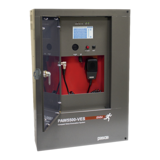
- Page 1 PAW5500-VES Compact wall-mount evacuation systems Models: PAW5502-V PAW5504-V PAW5506-V Cert. EN 54-16: 2008 User manual n° 0068/CPR/101-2018...
- Page 2 The warranty does not cover products that are improperly used or installed, mechanically damaged or damaged by liquids or the weather. If the product is found to be faulty, it must be sent to Paso free of charges for shipment and return.
-
Page 3: Table Of Contents
PAW5500-VES TABLE OF CONTENTS 1. WARNINGS 1.1 Power supply and earthing 1.2 Safety notes 2. INTRODUCTION 2.1 Overview of the system 2.2 Functional features 2.3 Typical confi guration 3. GENERAL DESCRIPTION 3.1 Front panel 3.2 Inside view 4. INSTALLATION AND CONNECTIONS 4.1 Wall mounting 4.2 Connections 4.2.1... -
Page 4: Warnings
1.2 SAFETY NOTES All PASO equipment is made according to the strictest international standards and complies with European Union requisites. For correct and eff ective use of the equipment it is important to be aware of all the characteristics by reading carefully these instructions and warnings. -
Page 5: Introduction
PAW5500-VES 2. INTRODUCTION 2.1 OVERVIEW OF THE SYSTEM The new PAW5500-VES range incudes three integrated voice evacuation systems for emergency facilities, designed specifi cally for wall-mounting and equipped with control units, certifi ed in compliance with EN 54-16:2008 / EN 54-4 standards. Depending on the model, these systems are capable of managing from 2 to 6 alarm zones, each driven by a single amplifi... -
Page 6: Typical Confi Guration
PAW5500-VES 2.3 TYPICAL CONFIGURATION PAW5500-VES Compact systems System manual... -
Page 7: General Description
PAW5500-VES 3. GENERAL DESCRIPTION 3.1 FRONT PANEL Backlit 4.3” display with touchscreen for selecting the Alert/Evacuation zones and for navigation for adjusting volume levels, confi guring the equipment and viewing failures. Integrated loudspeaker for playing back the output signals from the zones or the signals of the input sources and for replaying the acoustic signal indicating that a failure has been detected (beep). -
Page 8: Inside View
PAW5500-VES 3.2 INSIDE VIEW 7 off controlled input contacts. 3 off relay output contacts. Input for emergency microphone stations (max. 4). Input for paging microphone stations (max. 16). Input/output sockets REMOTE LINK A/B for connection to other PAW5500-VES units (overall max. of 6). Input terminal strip for auxiliary sources with precedence contact. -
Page 9: Installation And Connections
PAW5500-VES 4. INSTALLATION AND CONNECTIONS N.B. Please remind that the operations illustrated in this part of the manual must be carried out by specialised personnel ONLY, trained and qualifi ed in the equipment installation and maintenance. When the PAW is opened, parts entailing a high risk of electric shocks become accessible. -
Page 10: Connections
PAW5500-VES 4.2 CONNECTIONS N.B. Check that the main thermal-magnetic circuit breaker is switched OFF. If it is not, switch it OFF before carrying out any other activities in the cabinet as there is a danger of electric shocks. Proceed with connection of the various devices, referring to the appropriate points of the manual: CPU circuit Point 4.2.1 Connection of emergency units... -
Page 11: Connection Of Emergency Units
PAW5500-VES 4.2.1 CONNECTION OF EMERGENCY UNITS CPU CIRCUIT Use a CAT. 5e SF/UTP cable for connecting the EMERG. socket (11) to the ‘IN/OUT’ sockets of the PMB132 remote emergency units (up to 4). As an alternative, it is possible to connect up to 2 touch screen units TSB8500-V. The length of the link between the card-cage and the last station must not exceed 1000 metres at most. -
Page 12: Connection To Other Paw5500-Ves Units
PREC Not connected +VDC Serial + Fig. 1 Fig. 2 Serial – Shield For details concerning connection and the colours of the wires, refer to the manual of the B711-G base range (Paso # 11/636-B). PAW5500-VES Compact systems System manual... -
Page 13: Connection Of Music Input
PAW5500-VES 4.2.5 CONNECTION OF MUSIC INPUT CPU CIRCUIT The MUSIC terminals (15) are available for connecting outside music sources (CD player, tuner etc.). 4.2.6 CONNECTION OF INPUT CONTACTS CPU CIRCUIT There are 7 input contacts on the CONTACT terminal strip (9): the fi gure shows an example of a connection in which contacts 1, 2, 3, 5 and 6 are of the monitored type while contacts 4 and 7 are not. -
Page 14: Connection Of Relay Outputs
PAW5500-VES 4.2.7 CONNECTION OF RELAY OUTPUTS CPU CIRCUIT Three relay outputs are available on terminals R1, R2 and R3 (10) for signalling towards outside peripheral units. 4.2.8 21 TO 29 V CONNECTION CPU CIRCUIT Depending on how the PAW will be working, it is possible to receive a 21 to 24V power supply on the 24V terminals (20), with a maximum absorption of 50 mA. -
Page 15: Connection Of Standby Amplifi Er
PAW5500-VES The connections for 4 and 6 zone models (respectevely PAW5504-V and PAW5506-V) are shown in this fi gure. PAW5504-V PAW5506-V 4.2.10 CONNECTION OF THE STANDBY AMPLIFIER TERMINAL STRIP Using both terminal strip R (18) and A/B (19) it is possible to set a standby amplifer: here’s the connection of a PAW5502-V model (1 zone + standby amplifi... - Page 16 PAW5500-VES 3 ZONE SYSTEM + STANDBY 5 ZONE SYSTEM + STANDBY PAW5504-V PAW5506-V PAW5500-VES Compact systems System manual...
-
Page 17: Connection Of Power Supplies
PAW5500-VES 4.2.11 CONNECTION OF POWER SUPPLIES TERMINAL STRIP AND CHARGER N.B. Check that the main thermal-magnetic circuit breaker is switched OFF. If it is not, switch it OFF before carrying out any other activities in the cabinet as there is a danger of electric shocks. N.B. -
Page 18: Operational Conditions And Terminology
PAW5500-VES 5. OPERATIONAL CONDITIONS AND TERMINOLOGY Following is a list of how the operating conditions of the system are signalled and of the defi nitions used on the subsequent pages of the manual, completed by indications of a general nature. 5.1 SIGNALLING OF OPERATING CONDITIONS The PAW is designed to signal the diff... -
Page 19: Menu Structure
PAW5500-VES 7. MENU STRUCTURE The PAW allows system functions to be accessed through a series of Management Panels grouped, according to their operational typology and intended use, in Option Menus accessible from the MAIN MENU window. Furthermore, the following Option Menus have been assigned to diff erent levels of access, with reference to the various circumstances requiring diff erent degrees of skill and authorisation of the personnel assigned. -
Page 20: Using The System
PAW5500-VES <CONFIGURATION> MENU | 3 SYSTEM LEVEL Third level of access, for instructed personnel authorised to work on the advanced functions of the system and to alter the confi guration parameters, for starting up and altering the system. The relevant login password must be entered to access this menu. To go back to the main screen press ‘Main menu’. -
Page 21: Confi Guration Of The System
PAW5500-VES 8.1 CONFIGURATION OF THE SYSTEM Confi guration activities may be carried out only by qualifi ed personnel, suitably trained for this purpose. Password From the MUSIC MENU, go to the MAIN MENU and select < CONFIGURATION >. If access only with a password is enabled, ‘Enter confi... - Page 22 PAW5500-VES Rack confi guration In the CONFIGURATION menu, browse through the items and select ‘set>RACK CONFIG’. From here it is possible to confi gure all the basic settings of the system. D1) >> System On the ‘System confi guration’ screen page, use the [ + ] and [ – ] keys to set the following: Rack address: ID address of the PAW (from 0 to 5).
- Page 23 PAW5500-VES D3) >> Local emergency Screen page for setting the zones in which the emergency messages will be broadcast. The panel shows the situations of all the PAWs present in the system. Move in the table using the arrows and the Up and Dn keys. The zones selected in this window are called up directly on pressing the EVAC / ALERT / PTT keys if no selections are made in the emergency menu.
- Page 24 2, key 1 will correspond to zone 13, key 2 to zone 14 and so on). It is advisable to use Paso PMB106-G units as local stations. - Selection of an optional card, if any, present in the system (ACPAW-2IN or ACPAW-6IN).
-
Page 25: Music Menu
PAW5500-VES 8.2 MUSIC MENU SETTING THE AUDIO PARAMETERS OF BGM SOURCES Screen page Description of main panel Description of options Thanks to the diff erent panels, the new Music source control panel displayed by the PAW5500-VES range systems enable PAW in conditions of normal “Idle” state: independent selection of the various music sources. -
Page 26: Audio Setting> Menu
PAW5500-VES 8.3 <AUDIO SETTING> MENU SETTING THE AUDIO PARAMETERS OF THE PA SOURCES Screen page Description of the main panel Description of options Music and broadcast source control panel The options of the AUDIO SETTING displayed by the PAW in conditions menu enable access to the of normal “Idle”... - Page 27 PAW5500-VES set> MONITOR SPEAKER Management of monitor speaker On this panel, in addition to adjusting the Sources available for selection volume of the monitor speaker on the Local mic / MP3 PAW, it is possible to enable sounding Emergency units of the input and output signals of the Link A input equipment.
- Page 28 PAW5500-VES set> CLOCK Displaying current date and time On this screen page the system time can be displayed (it is not possible to make any changes, which are permitted at the higher access levels). Press ‘Escape’ to return to the < AUDIO SETTING > screen. set>...
-
Page 29: Inspection> Menu
PAW5500-VES 8.4 <INSPECTION> MENU SYSTEM STATUS INSPECTION This menu is intended for selecting options for system status inspection. It is for use by the personnel in charge of initial checking of the causes leading to a fault or to an emergency state. In this menu it is possible to select: To return to the main screen press Main menu. - Page 30 PAW5500-VES Label Category subject to diagnosis See panel Notes The diagnosis status is Primary and secondary power Power supplies reported for each monitored supplies element. The diagnosis status is Control input Local input contacts reported for each monitored element. The diagnosis status is Communication Internal communication of PAW reported for each monitored...
- Page 31 PAW5500-VES report> EVENT LOG Event log This panel displays a report showing the total number of faults and alarms recorded during system operation. Press Fault log view for a detailed view of the faults. Press Alarm log view for a detailed view of the alarms. To return to the INSPECTION menu, press Escape.
-
Page 32: Operator> Menu
PAW5500-VES 8.5 <OPERATOR> MENU MANAGEMENT OF EMERGENCY, FAULTY AND DISABLED CONDITIONS Menu from which to select options, to be used only by the personnel in charge of managing the system in the event of an emergency and/or a fault. If a login password was enabled at the time of confi guration, the following panel will appear: Enter the 4-digit numerical password (it is 2222 by default) and press Enter. - Page 33 PAW5500-VES Label Application See panel Notes Panel for testing the loudspeaker lines. Loudspeaker lines Loudspeaker lines On = test enabled Off = test disabled Panel for testing the local amplifi ers. Amplifi ers Amplifi ers On = test enabled Off = test disabled Panel for testing the input contacts.
- Page 34 PAW5500-VES set> CLOCK Setting of system date and time Panel for setting the system date and time. Press the following buttons: - Set date (date) - Set time (hour) and - Set cal. (calibration) to set these parameters. To return to the OPERATOR menu press ‘Escape’. After setting the desired date, press ‘Save date’...
-
Page 35: Configuration> Menu
PAW5500-VES 8.6 <CONFIGURATION> MENU MANAGEMENT OF ADVANCED SYSTEM FUNCTIONS AND CONFIGURATION CHANGES This option selection menu is for use only by specifi cally trained personnel authorised to work on advanced system functions and to modify the confi guration parameters, for system start-up and maintenance purposes. If a login password was enabled at the time of confi... - Page 36 PAW5500-VES set> IMP. REFERENCE Impedance acquisition and tolerance setting Panel for acquiring line impedance values and setting the tolerance threshold for the diagnostic tests. Press the appropriate buttons to access the sub-panels. Please note that if the new impedance and tolerance values are accepted, they will have to be saved by pressing the ‘Save’...
- Page 37 PAW5500-VES set> ALARM LEVELS Setting the alarm source level Panel for setting the output volume of the alarm sources connected to the PAW5500-VES. - Emergency units. - Hand-held paging local microphone. - LINK input (connection with other PAWs). To return to the CONFIGURATION menu, press Escape. set>...
- Page 38 PAW5500-VES Label Application See panel Notes In this panel the following are set: - PAW ID address (0 to 5). - Number of PAWs in the system. System confi guration - Attribution of standby amplifi er. System Standby amplifi er The total number of amplifi...
- Page 39 PAW5500-VES Label Application See panel Notes Panel for confi guring the controlled inputs. To go from one input to another (from 1 to 7), press Next or Prev. Press Mode to select one of the following modes: - Message input > Edit zone - Broadcast >...
- Page 40 2, key 1 will correspond to zone 13, key 2 to zone 14 and so on). It is advisable to use Paso PMB106-G units as local stations. Battery confi guration panel. By pressing ‘Change’ it is possible...
- Page 41 PAW5500-VES set> MESSAGE CONFIG. Setting of emergency messages The default messages (Alert, Evacuation and warning signal/chime) are stored in the PAW5500-VES internal fl ash memory. To further customise the system, it is also possible to load customised WAV fi les from external devices (an SD card or USB memory stick).
- Page 42 PAW5500-VES Password Setting a password Panel for enabling, disabling and customising the password for logging into the system service levels. The default passwords set are those shown here on the left. To change these settings and enter a new code, press the key associated with the menu in which the change is to be made and, on the next sub-panel, enter the new password.
-
Page 43: Criteria For Managing Priorities In Emergency Conditions
PAW5500-VES 8.7 CRITERIA FOR MANAGING PRIORITIES IN EMERGENCY CONDITIONS THE SYSTEM MANAGES EMERGENCY CONDITIONS ON THE BASIS OF TWO CRITERIA: 8.7.1 MANAGEMENT OF PRIORITIES ON THE BASIS OF HOW EMERGENCIES ARE ACTIVATED There are two possible types of activation: MANUAL EMERGENCY: emergency state activated by the operator by means of the LED pushbutton on the card-cage local controls or on the emergency microphone stations. -
Page 44: Manual Emergency - < Emergency > Menu
PAW5500-VES 8.8 MANUAL EMERGENCY THE PROCEDURE FOR MANAGING EMERGENCIES IN THE MANUAL MODE (TO BE CARRIED OUT BY AN AUTHORI- SED OPERATOR) IS DESCRIBED BELOW. 8.8.1 GENERAL INFORMATION The manual emergency mode can be accessed at any time and has priority both over any pre-recorded messages under way - that may have been activated by an external peripheral unit connected to the controlled inputs (9) –... - Page 45 PAW5500-VES 8.8.4 SENDING OUT OF A LIVE EMERGENCY NOTICE FROM REMOTE STATIONS Lift the safety lid on the station and press the EMERGENCY key once. It lights up steadily. The fact that the system has been placed in a state of emergency by the station is shown also on any other stations and on the PAWs linked to the system (with a fl...
-
Page 46: Automatic Emergency Alarm Status Activated By An External Peripheral Unit
PAW5500-VES 8.9 AUTOMATIC EMERGENCY ALARM STATUS ACTIVATED BY AN EXTERNAL PERIPHERAL UNIT THE PROCEDURE FOR MANAGING AN EMERGENCY STATUS SET OFF BY AN EXTERNAL PERIPHERAL UNIT THAT ACTIVATES THE INPUT CONTACTS PROGRAMMED TO ENABLE THE “ALARM STATUS” IS DESCRIBED BELOW. 8.9.1 ACTIVATION OF AN AUTOMATIC EMERGENCY In the event of activation of a programmed input contact the PAW stops its ‘Idle’... -
Page 47: Failure Status
PAW5500-VES 9. FAILURE STATUS THE PAW5500 VES HAS DIAGNOSTIC ROUTINES THAT MONITOR CONTINUOUSLY THE AVAILABILITY OF EMERGENCY SOURCES AND THE INTEGRITY OF CRITICAL PATHS OF THE SIGNALS ENSURING SYSTEM OPERATION IN EMERGENCY CONDITIONS. 9.1 SYSTEM OPERATION AND SIGNALLING IN A GENERIC FAILURE CONDITION •... -
Page 48: Technical Specifications
PAW5500-VES 10. TECHNICAL SPECIFICATIONS MODEL PAW5502-V PAW5504-V PAW5506-V Rated audio output @230V 500 W / D=2,5%* typical distortion at 25 W 0,025% Rated audio output @24V 400 W / D=10%* typical distortion at 25 W 0,025% Display 4.3” backlit with touch screen 480x272 pixels N°... - Page 49 PAW5500-VES MODEL PAW5502-V PAW5504-V PAW5506-V General information Mains power supply @230V 230 V 50/60Hz +10/-15% 230 V 50/60Hz +10/-15% 230 V 50/60Hz +10/-15% Consumption @230V 646 W full load 653 W full load 660 W full load (2amp active) (2amp active / 2amp stand-by) (2amp active / 4amp stand-by) Effi...
- Page 50 PAW5500-VES LIST OF OPTIONAL FUNCTIONS CLAUSE DESCRIPTION 7.6.2 Manual muting of voice alarm condition 7.7.2 Manual resetting of voice alarm condition Output for signalling a voice alarm condition Indication of fault aff ecting the transmission paths Indication of fault aff ecting the alarm zones Manual control of voice alarms Interface for external control device(s) Emergency microphone(s)
- Page 52 Voice alarm manual control Interface to external control device(s) Emergency microphone(s) 13.14 Redundant power amplifi er S.p.A. Via Settembrini, 34 - 20020 Lainate (MI) - Italia Tel. +39 0258077.1 • Fax +39 0258077.277 http://www.paso.it E-mail: info@paso.it UDT 06/18 | 11/826 | EN...
Need help?
Do you have a question about the PAW5500-VES Series and is the answer not in the manual?
Questions and answers