Table of Contents
Advertisement
Quick Links
Advertisement
Table of Contents

Related Manuals for Citizen CT-S4500


Summary of Contents for Citizen CT-S4500
- Page 1 LINE THERMAL PRINTER MODEL CT-S4500 User’s Manual...
- Page 2 WEEE MARK If you want to dispose of this product, do not mix it with general household waste. There is a separate collection systems for used electronics products in accordance with legislation under the WEEE Directive and is effective only within European Union. Wenn Sie dieses Produkt entsorgen wollen, dann tun Sie dies bitte nicht zusammen mit dem Haushaltsmüll.
- Page 3 (2011/65/EU) Full text of the EU declaration of conformity is available at the following internet address: http://www.citizen-systems.co.jp/english/support/download/printer/others/eu_doc/ IMPORTANT: This equipment generates, uses, and can radiate radio frequency- energy and if not installed and used in accordance with the instruction manual, maycause interference to radio communications.
- Page 4 Note that Citizen Systems is not responsible for any operation results regardless of omissions, errors, or misprints in this manual. Note that Citizen Systems is not responsible for any trouble caused as a result of using options or consumables that are not specified in this manual.
- Page 5 CITIZEN is a registered trademark of Citizen Watch Co., Ltd. All other trademarks are the property of their respective owners. Citizen Systems use these trademarks in accordance with the license of relevant owners. Copyright© CITIZEN SYSTEMS JAPAN CO., LTD. 2019 —...
- Page 6 SAFETY PRECAUTIONS ...WHICH SHOULD BE STRICTLY OBSERVED Before using this product for the first time, carefully read these SAFETY PRECAU- TIONS. Improper handling may result in accidents (fire, electric shock or injury). In order to prevent injury to operators, third parties, or damage to property, special warning symbols are used in the User’s Manual to indicate important items to be strictly observed.
- Page 7 Should it occur, immediately turn the printer off, unplug it from the supply outlet, and call your local Citizen Systems dealer. Do not handle the printer in the following ways: Do not subject the printer to strong impacts or hard jolts (e.g., being stepped on, dropped or struck).
- Page 8 CAUTION Do not use the printer under the following conditions. Avoid locations subject to vibration or instability. Avoid locations where the printer is not level. Ÿ The printer may fall and cause an injury. Ÿ The quality of printing may deteriorate. ...
- Page 9 Ÿ Neglecting these cautions may cause wires or insulation to break, which could result in electric leakage, electric shock, or printer failure. If the power cord sustains damage, contact your Citizen Systems dealer. Do not leave things around the electric outlet.
- Page 10 CAUTION Caution label is attached in the position shown in the following figure. Carefully read the handling precautions before using the printer. These labels indicate that the head becomes hot, so touching it may cause burns, and touching the auto cutter when opening the paper cover may cause cuts on hands.
- Page 11 Do not touch any of the moving parts (e.g., paper cutter, gears, active electric parts) while the printer is working. In case of trouble do not attempt to repair the printer. Ask Citizen Systems ser- vice for repair.
-
Page 12: Table Of Contents
THE TABLE OF CONTENTS 1. GENERAL OUTLINE ..............14 1.1 Features .................... 14 1.2 Unpacking ..................15 1.3 Model Classification ................16 1.4 Basic Specifications ................17 2. EXPLANATION OF PRINTER PARTS ...........19 2.1 Printer Appearance ................19 2.2 Inner area of the top cover ..............22 2.3 Other Built-in Functions .............. - Page 13 5. OTHER ...................70 5.1 External Views and Dimensions ............70 5.2 Printing Paper ..................73 5.3 Manual Setting of Memory Switches ..........77 5.4 Selecting and Setting the Cut Action ..........82 — —...
-
Page 14: General Outline
1. GENERAL OUTLINE This product is a line thermal printer capable of printing on media up to 4 inches wide. It can instantly print labels, tickets, and receipts containing a large volume of data that would not fit on normal width receipt paper. This printer has extensive features so it can be used in a wide range of applications. -
Page 15: Unpacking
1.2 Unpacking Make sure the following items are included with your printer. QUAN- NAME ILLUSTRATION TITY Printer AC Adapter *1 AC cord Media shaft *2 USB cable clamp Sample paper roll 1 roll Quick Start Guide *1: Standard model only *2: Use this with label paper and ticket paper that has a large core. -
Page 16: Model Classification
1.3 Model Classification Model numbers indicate printer features according to the following system. CT - S4500 A RS E - BK 1. Model name 2. AC adapter storage case A: None S: Yes 3. Interface RS: Serial RS-232C+USB ET: Ethernet+USB HET: Ethernet (USB host function) + USB BT: Bluetooth+USB HBT: Bluetooth (USB host function) + USB... -
Page 17: Basic Specifications
1.4 Basic Specifications Item Specifications Model CT-S4500 Print method Line thermal dot print method Print widths 104 mm/832 dots, 90 mm/720 dots, 82.5 mm/660 dots, 72 m/576 dots, 68.25 mm/546 dots, 64 mm/512 dots, 54.5 mm/436 dots, 54 mm/432 dots, 52.5 mm/420 dots, 48... - Page 18 Item Specifications Operating tempera- 5 to 40°C, 10 to 90% RH (no condensation) (65 μm ≤ paper thickness ≤ 85 μm) ture and humidity 10 to 80% RH (no condensation) (85 μm ≤ paper thickness ≤ 150 μm) Storage temperature -20 to 60°C, 10 to 85% RH (no condensation) and humidity Print head life *3...
-
Page 19: Explanation Of Printer Parts
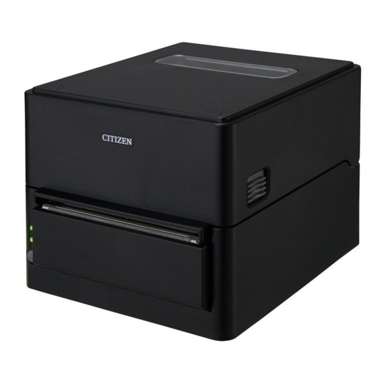
2. EXPLANATION OF PRINTER PARTS 2.1 Printer Appearance Names of parts Standard model Model with stored AC adapter 1. Media window Enables users to check the media level. 2. Top cover Opens upward so users can replace or set media. 3. - Page 20 4. Cover release buttons The cover is opened by pressing the buttons on both the right and left sides. 5. Auto cutter 6. AC adapter storage case Operation panel The operation panel includes 2 LEDs and 1 key. 1. Power LED Turns on when the power is turned on and turns off when the power is turned off.
- Page 21 Rear connectors (serial interface example) 1 2 3 1. USB interface 2. USB power supply connector Supplies power to USB devices. 3. Cash drawer kick-out connector Connect to the cable from the cash drawer. 4. DC jack Connects to the included AC adapter. 5.
-
Page 22: Inner Area Of The Top Cover
2.2 Inner area of the top cover 1. Thermal head Prints characters and graphic data on paper (paper rolls). 2. Upper sensor This sensor detects the media position. 3. Media damper When using roll media, absorbs tension generated by media feed operations to prevent print errors. - Page 23 11. Paper partition position adjustment button With this button pushed, move the paper partition to the left or right. 12. Paper width scale 13. Paper near-end (PNE) sensor Detects when the paper is near the end of the roll. 14. Paper near end sensor selector lever Adjust the position of the sensor to determine when it detects the end of the paper is near.
-
Page 24: Other Built-In Functions
2.3 Other Built-in Functions Buzzer Buzzes when errors occur or when operations or command operations are performed. Refer to 4.5 Error Indications User memory You can save user-defined logo and character data in this memory. Data remains stored in this memory even if the printer is turned off. For information on how to save data, refer to the Command Reference. - Page 25 Paper saving functions Memory switches MSW8-3 through MSW8-4 can be used to configure the settings below, which save paper. Ÿ Top margin suppression The printer back feeds the paper before printing which reduces the blank space at the top edge of the paper. The back feed amount can be specified.
-
Page 26: Setup
3. SETUP 3.1 Connecting the AC Power Cord For standard models Turn off the power. Insert the DC plug on the output side of the AC adapter into the DC jack in the printer. Insert the plug of the AC cord into an electrical outlet. AC adapter —... - Page 27 For models with stored AC adapter Turn off the power. Insert the plug of the AC cord into the AC port. Insert the plug of the AC cord into an electrical outlet. CAUTION Use only the specified AC adapter. ...
-
Page 28: Serial Interface Board
3.2 Serial Interface Board Data can be exchanged by serial communication. Connecting the Interface Cable Turn off the power. Confirm the orientation of the interface cable and connect it to the port. Insert the other connector firmly into the interface port of the host computer. CAUTION ... -
Page 29: Usb Interface
3.3 USB Interface Data can be exchanged by USB communication. Specifications Standard USB 2.0 specification-compliant Communication speed Supports 12 Mbps (Full-Speed) transfer Connecting the Interface Cable Turn off the power. Confirm the orientation of the interface cable and connect it to the port. Insert the other connector firmly into the interface port of the host computer. -
Page 30: Bluetooth Interface Board
3.4 Bluetooth Interface Board Names of parts Status LED The Bluetooth communication/connection/error status is indicated by this LED. USB connector Data can be exchanged by USB communication. CAUTION When using this interface board as a USB interface, do not connect USB cables to both the main unit side and interface board side. - Page 31 Pairing operation You need to perform the operations below the first time you establish a Bluetooth con- nection for Bluetooth data communication. 1. Detect Bluetooth devices 2. Configure pairing settings 1. Detecting Bluetooth devices Confirm that Bluetooth is enabled on the host PC before searching for Bluetooth devices.
- Page 32 Auto reconnection With iOS device Bluetooth communication, a connection between a paired iOS device and the printer is not automatically restored after it is lost. However, when auto recon- nection is enabled, the printer tries to reconnect with an iOS device after two-way com- munication is enabled and automatically restores the connection.
-
Page 33: Bluetooth Usb Host Interface Board
3.5 Bluetooth USB host interface board In addition to printer control via Bluetooth communication, Bluetooth USB host inter- faces can control peripheral devices connected via a USB port. Connecting a Peripheral Device Turn off the power. Connect the cable of a peripheral device to this port. CAUTION A peripheral device cannot be controlled if it is connected to the USB power supply port. - Page 34 For supplying power Connect a mobile device or other USB device. Power can be supplied to a connected USB device. * This port does not support USB data communication. Refer to 3.7 USB Power Supply Port Names of parts Panel button Control this interface board.
- Page 35 2. Configuring pairing settings Normally, selecting the printer during device detection will transition directly to pairing settings. CAUTION Some host PC configurations and models may not transition directly to pairing settings after the printer is selected during device detection. The operation required to configure pairing settings depends on whether SSP (secure simple pairing) is enabled on the host PC.
- Page 36 Enabling and disabling auto reconnect During self test, press the FEED button 3 times -> Auto reconnect = Valid During self test, press the FEED button 4 times -> Auto reconnect = Invalid At the end of self test, new setting will be printed as Auto reconnect [Valid] or [Invalid]. Refer to 4.3 Self Test Panel button operation Use the panel button on the rear of the Bluetooth board to operate this board.
- Page 37 Print the interface board state After starting the printer, pressing the panel button once prints the interface board state. Print example 1. Board firmware version 2. Address of equipped Bluetooth module 3. Bluetooth name 4. Response profile in Bluetooth transmission 5.
-
Page 38: Ethernet (Lan)/Wireless Lan Interface Board
3.6 Ethernet (LAN)/Wireless LAN Interface Board This section provides an overview of the interface board. For details on this board, in- cluding explanations about the USB host function and XML peripheral device support, refer to the separate manual. Connecting the Interface Cable Turn off the power. - Page 39 Connecting a USB Device The function assigned to each USB port differs. Connect the USB device to be connected to the correct place in reference to the fol- lowing figure. Ethernet Wireless LAN USB host model For peripheral device control Connect a peripheral device.
- Page 40 Panel button operation Board operations are performed using the panel button on the rear of the LAN board. Panel button Panel button Panel button Ethernet Wireless LAN Ethernet USB host model Enabling LAN connection Turn on the printer. Operation of this board will start about 20 seconds later. ...
- Page 41 LED Functions The tables below explain how to interpret LED indications. Ethernet Wireless LAN Ethernet USB host model 1. Wired LAN transmission speed Transmission speed LED (green) 100 Mbps 10 Mbps/Not connected Unlit 2. Wired LAN connection/transmission status Connection status LED (yellow) Connected Not connected...
- Page 42 Web Manager The interface board has a Web Manager function that can be used to connect to the board with a web browser and change board settings. Starting up Web Manager Start up a web browser. In the address field, input the board's IP address and then press [Enter]. HOME Screen This is the Web manager home screen.
- Page 43 CONFIG Screen This will display the Login dialog box shown below. Log in as an administrator and then configure interface board settings. User Name Input a board administrator user name. (Initial setting: admin) Password Input the administrator user password. (Initial setting: admin) ...
-
Page 44: Usb Power Supply Port
3.7 USB Power Supply Port Power (max. 2.1 A) can be supplied to a mobile device or other USB device by con- necting the cable of the USB device to the power supply port. Connecting Mobile Device or Other Device Turn off the power. - Page 45 For supplying power Connect a mobile device or other USB device. Power can be supplied to a connected USB device. * This port does not support USB data communication. Refer to 3.7 USB Power Supply Port CAUTION This port does not support USB data communication. ...
-
Page 46: Connecting The Cash Drawer
3.8 Connecting the Cash Drawer Turn off the power. Confirm the orientation of the cash drawer kick-out cable connector and connect it to the cash drawer kick-out connector at the back of the printer. Remove the screw for the ground wire. Screw the cash drawer’s ground wire to the body of the printer. - Page 47 (2) Electric characteristics 1) Drive voltage: 24 VDC 2) Drive current: Approx. 1 A max. (not to exceed 510 ms.) 3) DRSW signal: Signal levels: “L” = 0 to 0.5 V, “H” = 3 to 5 V (3) DRSW signal Status can be tested by commands.
-
Page 48: Precautions For Installing The Printer
3.9 Precautions for Installing the Printer This printer can only be positioned horizontally. It cannot be positioned vertically or on a wall. Horizontal position Vertical position CAUTION Do not use the printer under the following conditions. Avoid locations subject to vibration or instability. ... -
Page 49: Adjusting The Paper Near-End Sensor
3.10 Adjusting the Paper Near-end Sensor Change the settings of the paper near-end sensor to set the position at which the near- end of the paper is detected. Open the top cover. Adjust the sensor position by moving the paper near end sensor selector lever while gently pushing it in. -
Page 50: Roll Paper Partition
3.11 Roll paper partition When using roll paper narrower than 112 mm in width, move the paper partition to a suitable position. Turn off the power. Press the cover release buttons on both the right and left sides to open the top cover. Move the paper partition left or right while pressing the paper partition position adjust- ment button to align it with the paper width position on the paper width scale. - Page 51 CAUTION When opening the top cover, be careful not to touch the entrance of the blade of the auto cut- ter. The print head is very hot immediately after printing. Be careful not to touch it with your hands.
-
Page 52: Loading Paper
3.12 Loading Paper Turn on the power. Press the cover release buttons on both the right and left sides to open the top cover. Load the roll paper with the printable side of the paper facing outward as shown by arrow A and with no slack. - Page 53 Continuous Label media — —...
- Page 54 Label media (when using a media shaft) CAUTION When opening the paper cover, be careful not to touch the entrance of the blade of the auto cutter. The print head is very hot immediately after printing. Be careful not to touch it with your hands.
- Page 55 Make sure the paper is flush with the left media guide and then adjust the position of the right media guide to match the paper width. From the front of the printer, set in front of the edge of media by approximately 10 mm. CAUTION If force is used to push the right movable media guide against the paper, improper feeding of the paper may occur, which may have an impact on printing.
- Page 56 Use something with a sharp point such as the tip of a pen to slide the head balance adjustment slider located near the thermal head left or right along the paper size scale (inches) so that the position of the notch in the slider matches the paper width. media size scale Thermal printhead Head balance adjustment slider...
-
Page 57: Adjusting Media Sensor Positions
3.13 Adjusting Media Sensor Positions This section describes the procedure to adjust sensors when loading media. Transmis- sive and reflective sensors can be used for the media sensors. Range of Paper Sensor Adjustment The following figure illustrates the range of media sensor adjustment. Left fixed media guide 112 mm (Max. - Page 58 Transmissive Sensor Adjustment Adjust the position of the bottom sensor and upper sensor in accordance with the media width. Move the bottom sensor and upper sensor by the same number of steps from the position of the triangle (). Upper sensor Thermal head Bottom sensor...
-
Page 59: Selecting A Paper Type
3.14 Selecting a Paper Type Paper type selection is available by the combination of memory switches MSW4-4 and MSW4-5 by the used of “Memory Switch Select Mode”. In addtion, the following procedure is available. Enter Selecting Paper Type mode. 1) With the top cover open, turn on the printer power switch while pressing and holding the FEED key. -
Page 60: Calibrating The Paper Sensor
3.15 Calibrating the Paper Sensor Calibrate the paper sensor to suit the actual paper you are using before using label paper or black mark paper. Before executing this mode, use the paper selection mode or the MSW-4 and MSW4-5 settings to set the paper type you want to use. Refer to 3.14 Selecting a Paper Type Refer to 5.3 Manual Setting of Memory Switches Enter Adjusting Paper Sensor mode. - Page 61 Adjust media sensor sensitivity and measure the paper length. If you press the FEED key, the buzzer sounds once for a short time, the label is fed, and me- dia sensor sensitivity adjustment and paper length measurement are performed automatically regardless of the setting of MSW4-1.
-
Page 62: Precautions For Creating Applications And Practical Operations
If this is the case, try using a cable with ferrite cores on both ends, which are very ef- fective at eliminating EMI. 3.17 Download Site for Various Electronic Files You can view support information and download the latest documents, drivers, utilities, etc. from the following site. http://www.citizen-systems.co.jp/support/download/printer/ct-s4500/ — —... -
Page 63: Maintenance And Troubleshooting
4. MAINTENANCE AND TROUBLESHOOTING 4.1 Periodic Cleaning Printing may not be performed normally if the thermal head, paper feed roller (platen roller), or sensor protection sheet are dirty, so cleaning should be performed regularly (every two or three months). Turn off the power. While pressing the cover release buttons on both sides, open the top cover. -
Page 64: Clearing A Cutter Error
4.2 Clearing a Cutter Error If the auto cutter stops during the auto cutter operation with the blade of the auto cutter in the open position due to foreign matter entering, paper jamming, etc., the Status LED flashes. When a cutter error occurs, resolve the cutter error with the following procedure. -
Page 65: Self Test
4.3 Self Test You can use self test to check for printer problems. Performing a self test operation While paper is loaded, press and hold the FEED button and turn on the power. Hold the FEED button down for about one second until the buzzer sounds. Release the button to start self test. -
Page 66: Hexadecimal Dump Printing
4.4 Hexadecimal Dump Printing Print received data in hexadecimal. If problems such as missing or duplicated data occur, this function allows you to check whether or not the printer is receiving data cor- rectly. How to do hexadecimal dump printing Load paper. -
Page 67: Error Indications
4.5 Error Indications Paper end, paper near-end The end of paper is detected in two stages, paper near-end and paper end. For paper near-end, the status LED lights amber. Prepare to replace the paper. For paper end, the status LED lights red and the buzzer sounds. Load a new paper roll. - Page 68 The status display for various messages is shown below. Status Color Status LED Buzzer*1 Paper near-end Amber Paper-end Yes*2 Cover open*3 No*2 Cover open II*4 No*2 Cutter locked Low-voltage error High-voltage error System error Memory error Print head hot Amber Black mark/label gaps detec- tion error Wait for Macro Execution...
-
Page 69: Paper Jams
4.6 Paper Jams Take care to avoid obstruction of the paper outlet and paper jamming around the outlet during printing. If paper cannot get out of the printer, it can roll up on the platen inside the printer and cause an error. If the paper wraps around the platen, open the paper cover and carefully pull the paper out. -
Page 70: Other
5. OTHER 5.1 External Views and Dimensions (Unit: mm) Standard model 216.2 — —... - Page 71 Standard AC adapter-equipped model 216.2 — —...
- Page 72 Optional interface-equipped model Protrusion amount at back of optional interface (P) Serial RS-232C: 1.5 mm Ethernet, Ethernet USB host, and wireless LAN: 20 mm Bluetooth and Bluetooth + USB host: 19 mm 216.2 — —...
-
Page 73: Printing Paper
5.2 Printing Paper Use the paper shown in the following table or paper of the same quality. Paper type Product name Recommended Nippon Paper TF50KS-E thermal roll paper Oji Paper PD150R, PD160R Mitsubishi Paper Mills P220AE-1 Recommended ther- Nippon Paper HD75 mal label roll paper Ricoh 150LA-1P-ST (Unit: mm) - Page 74 Label media Cut position Paper feeding direction Printable area (Unit: mm) Mark Item Dimensions Label backing width 58 to 112 0/-1 Label width 54 to 108±0.5 Left edge of label 2±0.5 Print width 45 to 104 Top margin 2+2/-2 Print length 21 to 296 Bottom margin...
- Page 75 CAUTION Make sure the cut position is between labels. Cut the backing paper. Do not cut label paper (tack paper). Always re-calibrate the paper sensor whenever you change the label backing paper type. Do not use full-surface label media. ...
- Page 76 CAUTION The black mark PCS value should be at least 0.90. Concerning the accuracy of feeding with black mark detection, allow for an error of ±2 mm from the reference print position, or for a maximum error of -5% from the value set for the print length.
-
Page 77: Manual Setting Of Memory Switches
5.3 Manual Setting of Memory Switches Memory switches are used to set various printer settings. Memory switches can be set manually, or by utilities or commands. This section explains how to perform manual settings. For information on how to set the memory switches using commands, please refer to the Command Reference. - Page 78 Press the FEED button. A setting is printed each time the FEED button is pressed in order through the cycle. When the current settings are printed, the COVER LED lights. Press the FEED button until the setting you want is printed. Press the FEED button for at least two seconds.
- Page 79 The function of each memory switch is shown in the following table. (Shaded values are factory settings.) Switch no. Function MSW1-1 Power ON Info Valid Not Send MSW1-2 Buffer Size 4 Kbytes 45 bytes MSW1-3 Busy Condition Full/Err Full MSW1-4 Receive Error Print“?”...
- Page 80 Switch no. Function MSW6-1 Act. For Driver Invalid Valid MSW6-2 Character Space Invalid Valid MSW6-3 USB Power Save Invalid Valid MSW6-4 Reserved Fixed — MSW6-5 Reserved Fixed — MSW6-6 Reserved Fixed — MSW6-7 Reserved Fixed — MSW6-8 Reserved Fixed — Switch no.
- Page 81 Switch no. Function Initial setting Setting value MSW10-1 Print Density 100 % 70 %, 75 %, 80 %, 85 %, 90 %, 95 %, 100 %, 105 %, 110 %, 115 %, 120 %, 125 %, 130 %, 135 %, 140 % MSW10-2 Print Speed Level 9...
-
Page 82: Selecting And Setting The Cut Action
5.4 Selecting and Setting the Cut Action Use the following procedure to select and set the cut action for when a cut command is received. Changing between forced partial and forced full is possible only with this procedure. Changing between cutting as commanded and forced partial (forced full) is possible also with memory switch MSW4-8. - Page 83 CT-S4500_UM_100_EN PMC-1906 June 2019...
Need help?
Do you have a question about the CT-S4500 and is the answer not in the manual?
Questions and answers