Citizen CT-S4000DC User Manual
Line thermal printer
Hide thumbs
Also See for CT-S4000DC:
- User manual (160 pages) ,
- Quick start manual (41 pages) ,
- Quick start manual (2 pages)

Related Manuals for Citizen CT-S4000DC


Summary of Contents for Citizen CT-S4000DC
- Page 1 LINE THERMAL PRINTER MODEL CT-S4000/CT-S4000DC CT-S4000L/CT-S4000DCL CT-S4000M/CT-S4000DCM User’s Manual...
- Page 2 WEEE MARK...
- Page 3 Declaration of Conformity This printer conforms to the following Standards: Low Voltage Directive 73/23/EEC, 93/68/EEC and the EMC Directive 89/336/EEC, 92/31/EEC, 93/68/EEC. LVD : EN60950-1 EMC : EN55022 Class A EN61000-3-2 EN61000-3-3 EN55024 This declaration is applied only for 230V model. IMPORTANT: This equipment generates, uses, and can radiate radio frequency energy and if not installed and used in accordance with the instruction manual, may cause interference to radio communications.
- Page 4 ● Note that Citizen Systems is not responsible for any operation results regardless of missing, error, or misprinting in this manual. ● Note that Citizen Systems is not responsible for any trouble caused as a result of using options or consumables that are not specified in this manual.
- Page 5 SAFETY PRECAUTIONS ... WHICH SHOULD BE STRICTLY OBSERVED Before using this product for the first time, carefully read these SAFETY PRECAUTIONS. Improper handling may result in accidents (fire, electric shock or injury). In order to prevent injury to operators, third parties, or damage to property, special warning symbols are used in the User’s Manual to indicate important items to be strictly observed.
- Page 6 Should it occur, immediately turn the printer off, unplug it from the supply outlet, and call your local Citizen Systems dealer. Do not handle the printer in the following ways: ■ Do not allow the printer to sustain strong impacts or hard jolts (e.g., trampling, dropping, striking with a hard edge).
- Page 7 CAUTION Do not use the printer under the following conditions. ■ A state subject to vibration or unstable state. ■ A state with this product slanted. • Otherwise dropping may cause injury. • Poor print quality may occur. ■ A state where the printer ventilation holes are obstructed by a nearby wall or other equipment.
- Page 8 • Neglecting these cautions may cause wires or insulation to break, which could result in leakage, electric shock, or printer failure. If the power cord sustains damage, contact your Citizen Systems dealer. ■ Do not leave things around the supply outlet.
- Page 9 CAUTION Caution label is attached on the position shown in the following figure. Carefully read the precautions in handling before using the printer. THESE LABELS INDICATE THE RISK OF ANY INJURY DUE TO "HIGH TEMPERATURE" OF THE PRINT HEAD AND "SAW- TOOTHED EDGE"...
- Page 10 ■ Do not touch any of the moving parts (e.g., paper cutter, gears, active electrical parts) while the printer is working. ■ In case of trouble do not attempt to repair the printer. Ask Citizen Systems service for repair. ■ Be careful that the printer cover does not entrap your hands or fingers.
-
Page 11: Table Of Contents
THE TABLE OF CONTENTS 1. GENERAL OUTLINE ..............9 1.1 Features ..................9 1.2 Unpacking ..................10 1.3 Model Classification ..............10 1.4 Basic Specifications ..............11 2. EXPLANATION OF PRINTER PARTS........12 2.1 Printer Appearance ..............12 2.2 Printer Cover Inside ..............14 2.3 Other Built-in Functions ............... -
Page 12: General Outline
1. GENERAL OUTLINE This product are thermal line printers designed for use with a broad array of terminal equipment including data, POS, and kitchen terminals. With extensive features, they can be used in a wide range of applications. 1.1 Features ●... -
Page 13: Unpacking
1.2 Unpacking When unpacking the printer, confirm that the following are provided: ● Printer: ● AC power cord : 1 (for CT-S4000, CT-S4000L, CT-S4000M) ● User’s manual (This manual): 1 ● Sample paper roll: 1 roll ● Partition: ● Screw: User’s manual AC power cord (This manual) -
Page 14: Basic Specifications
Approx. 70W (in normal printing) Weight Approx. 2.3 Kg for CT-S4000, CT-S4000L, CT-S4000M Approx. 2.0 Kg for CT-S4000DC, CT-S4000DCL, CT-S4000DCM Outside dimensions 177 (W) × 213 (D) × 147 (H) mm Operating temperature 5 to 45°C, 10 to 90% RH (No condensation) -
Page 15: Explanation Of Printer Parts
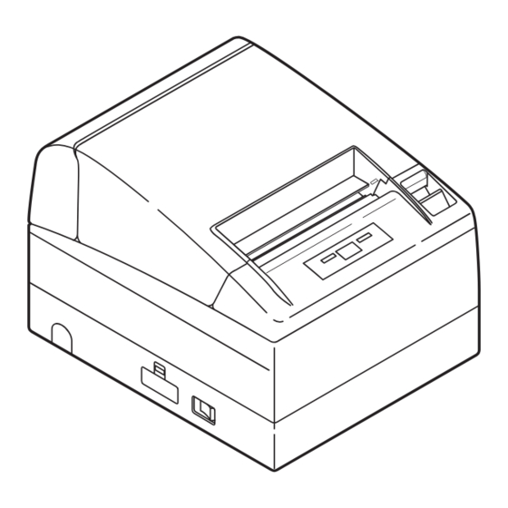
2. EXPLANATION OF PRINTER PARTS 2.1 Printer Appearance Printer cover Cover open button Side opening Power switch Rear connector Side opening Operation panel (Front view) (Rear view) ● Printer cover Paper is loaded under this cover. ● Cover open button To refill or replace paper, open the printer cover by pulling the cover open button forward. - Page 16 Operation Panel POWER LED ERROR LED FEED button ● POWER LED Illuminated when the printer power is on and off when the printer power is off. May blink or light in a special mode or in case of failure. ● ERROR LED Illuminated or blinks when paper is empty or in case of failure.
-
Page 17: Printer Cover Inside
For the registration method, refer to Command Reference Manual in separate document. To acquire the Command Reference Manual, contact your Citizen Systems dealer. ● Memory switch Setting of various kinds of functions can be stored in nonvolatile memory. -
Page 18: Preparation
3. PREPARATION 3.1 Connecting the AC Power Cord 1. Turn off the printer power switch. 2. For AC power type (with built-in power supply), connect the AC power cord to the AC inlet at the back of the printer and plug the AC power cord into the wall outlet. -
Page 19: Connecting Interface Cables
3.2 Connecting Interface Cables Confirm that the power switch is OFF and connect the interface cable. Orient the interface cable terminal correctly and insert it into the interface connector. Parallel Interface USB Interface Serial Interface CAUTION! ■ When disconnecting the cable, always hold the connector. ■... -
Page 20: Connecting The Cash Drawer
3.3 Connecting the Cash Drawer 1. Confirm that the power switch is OFF. Cash drawer 2. Confirm the top and bottom of the cash kick-out connector drawer cable connector and insert it into the cash drawer kick-out connector at the back of the printer. -
Page 21: Installing The Printer
3.4 Installing the Printer The printer can be installed horizontally, vertically, and on the wall. At the time of shipment, the printer is set for horizontal installation. To install the printer vertically or on the wall, the following adjustments are required. 1. -
Page 22: Setting Dip Switch
3.6 Setting DIP Switch The DIP switch is present on the serial interface board. The function of each switch is as shown below. DIP switch Interface board mounting screws CAUTION! ■ As for the setting of the serial interface, it gives priority to the setting of the memory switch rather than the DIP switch as the factory default. -
Page 23: Adjusting The Paper Near-End Sensor
3.7 Adjusting the Paper Near-end Sensor 1. Lightly push in the paper near-end sensor unit. 2. Move the paper near-end sensor unit to the right and left while keeping to press it. The position to be set varies in accordance with the setting of the printer, horizontal or vertical, or diameter of the paper roll as shown in the following figure. -
Page 24: Maintenance And Troubleshooting
4. MAINTENANCE AND TROUBLESHOOTING 4.1 Setting/Replacing the paper roll 1. Pull the cover open button forward. 2. Open the printer cover. 3. Insert a paper roll with its print area facing down as shown in the figure and pull out the paper end straightforward several cm (or inches) out of the printer. -
Page 25: Periodic Cleaning
4.3 Periodic cleaning If the print head or platen is dirty, clear printing is not available or fault may occur. If paper dust or the like is present on the sensor protection sheet, label paper or blackmark paper may not be detected correctly. Periodic cleaning in accordance with the following procedure is recommended. -
Page 26: Self-Printing
4.4 Self-printing Insert paper into the printer. With the FEED button pressed and held, turn the printer power on, keep the FEED button held for about 1 second, and then release the FEED button. The printer starts self-printing. The printer prints model name, version, DIP switch setting, memory switch setting, and built-in fonts. -
Page 27: Error Indication
4.6 Error Indication ● Paper end Paper out is detected in two steps: paper near-end and paper end. ERROR LED will light when the paper is empty. If paper end is detected, refill the paper. If the printer cover is open, a paper-end is detected. ●... -
Page 28: When The Paper Cover Cannot Be Opened
Lighting and blinking status of each error including the above is shown below. Status POWER LED ERROR LED Buzzer Paper-end Lights Lights Paper near-end Lights Lights Printer cover open Lights Lights Printer cover open Lights error *1 Cutter lock error Lights Head overheat error Lights... -
Page 29: Other
5. OTHER 5.1 External Views and Dimensions (Unit: mm) 5.2 Printing Paper Use the print paper shown in the following table or the paper with equivalent quality. Paper Type Product Name Recommended thermal F230AA, P220AG, HP220A, HP220AB-1, P220AB, P220AE-1, paper roll PB670 (Red/Black), PB770 (Blue/Black) from Mitsubishi Paper TF50KS-E2D from Nippon Paper PD150R, PD160R from Ohji Paper... - Page 30 When using “label paper” with CT-S4000L and CT-S4000DCL, refer to the following. Use the following paper or the equivalent paper. Paper type Product name Recommended thermal label paper 150LA-1 from Ricoh, GG40/P22/G6B from Ojitac, HD75 from Nippon Paper a) Label paper *L Full cut position Paper feeding...
- Page 31 b) Black mark paper (BM paper) Cut position Printable area Paper feeding direction Black Mark (printed on the reverse) Unit: mm Mark Item Dimensions Right edge of black mark 15 or more Left edge of black mark 0 to 1.5 Black mark height Cut position in black mark 2.5 Top margin...
-
Page 32: Manual Setting Of Memory Switch
5.3 Manual Setting of Memory Switch Memory switches can be set manually or by a command. For manual setting, refer to the next page. The function of each memory switch is shown in the following table. (The white-on-black characters are factory setting.) Switch No. - Page 33 Switch No. Setting 0 (OFF) 1 (ON) Memory SW5-1 Buzzer Valid Invalid SW5-2 Line Pitch SW5-3 USB Mode Virtual COM Printer Class SW5-4 Reserved Fixed − SW5-5 Reserved Invalid − SW5-6 Reserved Fixed − SW5-7 Reserved Fixed − SW5-8 Reserved Fixed −...
- Page 34 Entering memory switch setting mode. Set paper in the printer and keep the printer cover open. With the FEED button pressed and held, turn the printer power on, and then press the FEED button twice. Close the cover. If the current settings of the memory switch etc.
-
Page 35: Selecting Paper Type
*L, *M 5.4 Selecting Paper Type Paper type selection is available by the combination of memory switches SW4- 4 and SW4-5 by the used of “Memory Switch Select Mode”. In addtion, the following procedure is available. 1 Enter Selecting Paper Type mode. 1)Open the printer cover and remove paper. - Page 36 Black Mark sensor Label light receiving sensor *L Metal frame Level indicator Label paper sensor Black Mark paper adjuster *L sensor adjuster Label light emitting sensor *L 1 Enter Adjusting Paper Sensor mode. Open the printer cover, remove paper, and then set the printer power switch to ON.
-
Page 37: Full Cutting Label Paper
5.6 Full cutting label paper When full-cutting the label paper with the printer installed horizontally,Be sure that the guide plate is mounted on the paper exit of the printer cover. (This guide plate was set to the printer at the time of factory shipment.) The Guide Plate prevents cut paper from dropping in the printer. - Page 38 TB74915-00F 1.00-0804 Printed in Japan...
Need help?
Do you have a question about the CT-S4000DC and is the answer not in the manual?
Questions and answers