Sandel SN4500 Pilot's Manual
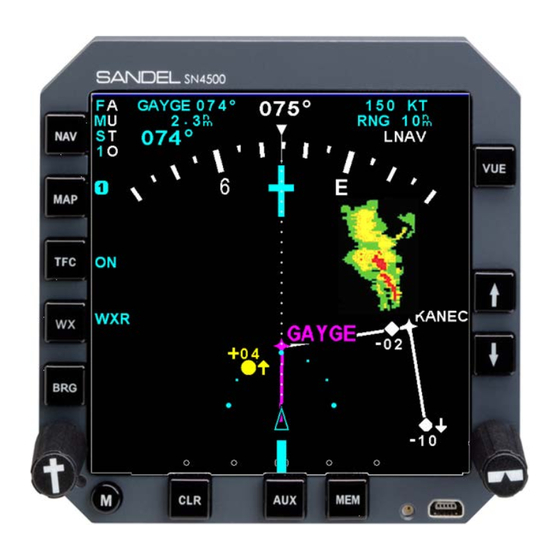
Primary navigation display with reversionary attitude mode
Hide thumbs
Also See for SN4500:
- Maintenace manual (6 pages) ,
- Pilot's manual (110 pages) ,
- Manual (2 pages)

Related Manuals for Sandel SN4500


Summary of Contents for Sandel SN4500
- Page 1 SN4500 Primary Navigation Display with (This page intentionally left blank) Reversionary Attitude Mode Pilot’s Guide 82009-PG, REV D1 SANDEL SN4500 PILOT’S GUIDE PAGE...
-
Page 2: Copyright
Note: Because aircraft vary in their installed equipment, it is without notice at the discretion of Sandel Avionics, Inc. important to note that what is displayed on the SN4500 may vary depending on the presence or absence of equipment. Copyright Please keep in mind that it is required by Federal Aviation Copyright 2010 Sandel Avionics, Inc. -
Page 3: Approvals
C6d: Direction Instrument, Magnetic (Gyroscopically minded readers, such as “selected radial” and “magnetic heading”. Stabilized Terms, which are specific to the SN4500, will be placed in the C34e: ILS Glide Slope Receiving Equipment glossary. C35d: Airborne Radio Marker Receiving Equipment... -
Page 4: Table Of Contents
Conventions Used in This Manual Bearing Pointers Table of Figures BRG Menu Effectivity, Revision and Errata History CHAPTER 6 MAP OPERATIONS CHAPTER 1 WELCOME TO THE SN4500 Overview What is the SN4500 Internal Database CHAPTER 2 DISPLAY OVERVIEW Map Controls and Displays... -
Page 5: Table Of Figures
Figure 2-2 Display Areas Traffic Display Mode Figure 3-1 Introduction Screen Altitude Mode Figure 3-2 SN4500 Display with Compass Card Traffic Overlay with Moving Map Figure 3-3 NAV Source Annunciations Figure 3-4 Full View Traffic Display with Stormscope and Data Link Weather... -
Page 6: Effectivity, Revision And Errata History
Updated for software version 1.03. • With the exception of the superseding information contained in this Page iii: Patent information section, operation of the SN4500 is as described in the SN4500 updated. Pilot’s Guide referenced above. • Page XI Errata updated. -
Page 7: Chapter 1 Welcome To The Sn4500
A comprehensive set of maintenance pages allows the installer to simply specify the make and model of the installed equipment, and the SN4500 will configure itself accordingly. 82009-PG, REV D1 SANDEL SN4500 PILOT’S GUIDE... -
Page 8: Chapter 2 Display Overview
CHAPTER 2 DISPLAY OVERVIEW display SN4500 Physical Features area The SN4500 physical layout consists of a full four inch display, twelve backlit pushbuttons, two knobs with push to select, a power on indicator, and one USB connector. Primary display area... - Page 9 The information is displayed in the same color as the associated bearing pointer. Also note that the tail of each pointer can be used to determine the bearing from the selected NAV source. 82009-PG, REV D1 SANDEL SN4500 PILOT’S GUIDE PAGE 82009-PG, REV D1 SANDEL SN4500 PILOT’S GUIDE PAGE...
-
Page 10: Data Color Coding
DISPLAY OVERVIEW DISPLAY OVERVIEW Data Color Coding Color Data displayed Data displayed on the SN4500 is color coded as follows: • Inner marker indicator • Color Data displayed Traffic targets WHITE • New Stormscope® data • Information associated with the primary VHF •... - Page 11 • ILS1 / ILS2 Indicator • ORANGE Heading bug and associated data (This page intentionally left blank) • BLUE Outer marker indicator • PURPLE 82009-PG, REV D1 SANDEL SN4500 PILOT’S GUIDE PAGE 82009-PG, REV D1 SANDEL SN4500 PILOT’S GUIDE PAGE...
-
Page 12: Chapter 3 Basic Operation
SN4500 refers to selecting the data for a given display. example, either the VOR or the GPS receiver can drive a bearing pointer. Controlling the SN4500 refers to tailoring the display to suit the immediate situation. For example, the pilot may decide to turn off a bearing pointer completely during the enroute portion of the flight and use it only during an approach. -
Page 13: Selecting The Primary Nav Source
[NAV] button will not change sources. Instead, the following message is displayed: “NAV TUNED TO ILS”. To The SN4500’s course pointer and CDI can be driven from VOR or defeat the override and restore the function of the [NAV] button, GPS data. -
Page 14: 360-Degree Full View And 70-Degree Arc View
The auto-slew function is enabled/disabled in the NAV menu as described in Chapter 4. The SN4500 allows the pilot to switch between a traditional 360- degree FULL view of the compass rose and a forward-looking 70- Remote Course and Heading Knobs degree ARC view. -
Page 15: Display Brightness
The interface to the aircraft Figure 3-6 Brightness Adjustment dimmer bus is enabled during installation of the SN4500. The display brightness can be set for either automatic or manual adjustment mode. In automatic mode the display brightens and dims based on ambient lighting conditions. -
Page 16: Chapter 4 Nav Operation
GPS/FMS units can be set for automatic or manual sequencing of • Press [M] to exit the menu and return to normal operation. waypoints in the active flight plan. This can be set on the SN4500 Auto-Slew Function through the NAV Menu or may be available on an external switch. -
Page 17: Course Pointer Display Function
Rotate the heading bug knob to select the desired option. • Press [M] to exit the menu and return to normal operation. 82009-PG, REV D SANDEL SN4500 PILOT’S GUIDE PAGE 4-3 82009-PG, REV D SANDEL SN4500 PILOT’S GUIDE PAGE 4-4... - Page 18 Lateral Precision Approach Lateral Precision Approach with Vertical Guidance Lateral Navigation with Vertical Guidance Approach Lateral Navigation Approach Figure 4-7 GPS WAAS Annunciator Descriptions 82009-PG, REV D SANDEL SN4500 PILOT’S GUIDE PAGE 4-5 82009-PG, REV D SANDEL SN4500 PILOT’S GUIDE PAGE 4-6...
-
Page 19: Chapter 5 Bearing Pointers
NAV source. The tail of each pointer indicates the bearing from the NAV source. Either pointer can be driven by any navigation source interfaced to the SN4500: VOR, GPS/FMS, or ADF. When a GPS/FMS is selected as the bearing pointer source, the bearing pointer indicates the bearing and distance to the current active waypoint. -
Page 20: Chapter 6 Map Operations
6,000 feet or longer. Map Controls and Displays SN4500 allows you to save such a map configuration in one of four map memories and then recall it as needed. Information associated with control of the map is displayed as... -
Page 21: Map Memories
High Power H PWR Cyan Any memory that is empty is skipped during the MAP rotation sequence. In the default setup of the SN4500, memories 1, 2 and 3 High Level HI LV Cyan contain default settings, and memories S and 4 are empty. -
Page 22: Getting Started - Example
[MAP] to display map memories 1, 2 and 3. Getting Started - Example Map Setup The default SN4500 map memories are set up as follows: After you are familiar with the displaying map information based on S: Empty... -
Page 23: Map Memory Settings
Press [MAP] to display the MAP menu. functions are all accessed through the map memory menu. To access the map memory menu: 82009-PG, REV D SANDEL SN4500 PILOT’S GUIDE PAGE 6-7 82009-PG, REV D SANDEL SN4500 PILOT’S GUIDE PAGE 6-8... -
Page 24: Storing Settings Into Preset Memories
• Rotate the left knob to highlight “MENU SEL”. • Rotate the right knob until “MEMORY” in the right column is highlighted. 82009-PG, REV D SANDEL SN4500 PILOT’S GUIDE PAGE 6-9 82009-PG, REV D SANDEL SN4500 PILOT’S GUIDE PAGE 6-10... -
Page 25: Copying Map Settings Into The Scratchpad
The • Map memory "DEFAULT" SN4500 will automatically remove items from the display if the total number of items is too great to display. When this occurs, it is •... -
Page 26: Chapter 7 Weather Display Interface
“S” for strike mode, or “C” for cell mode. Error messages are detailed in the WX-500 User’s Guide. New cell/strike symbols are shown on the SN4500 in white for 30 seconds after which they are shown in green. Cell/strikes older than 3 minutes are removed from the display. -
Page 27: Fis-B Datalink Weather
: Causes the WX-500 to send a series of simulated DEMO Rotate the left knob to select the desired function in the left column. lightning strikes to the SN4500 display. The following options are available: • LTNG SRC: Rotate the right knob to select the lightning •... -
Page 28: General Operation
WSI InFlight data link Note: FIS-B lightning may be co-displayed with WX-500 lightning receiver and the SN4500 contains software version 3.00 or above strike information, when a WX-500 is also connected to the SN4500. enabled with the Datalink Weather option. Precipitation Intensity... -
Page 29: Fis-B Services Backgrounder
By the time this information is received in the aircraft and displayed on the SN4500, it will be aged from 3 to 11 minutes depending on • To promote pilot awareness of own ship location with the amount of data transmitted. -
Page 30: Examples
The reception age uses the time the tile is received from the aircraft receiver by the SN4500. The SN4500 displays to the right of the WX button the time in minutes since any mosaic tiles have been received. - Page 31 WEATHER DISPLAY INTERFACE Most likely, a flight crew will recognize the cloud deck below and consider that the conditions represented on the SN4500 in figure 7- 10 are well below the aircraft. However, it may not be so apparent when flying between cloud layers at figure 7-13 illustrates. When...
-
Page 32: Chapter 8 Traffic Display Interface
Traffic Alert Alerting traffic with no Note: The SN4500 can be interfaced to a TCAS II processor but will bearing and no altitude No Bearing / No function only as a traffic display as vertical guidance information information available. -
Page 33: Absolute Altitude Vs. Relative Altitude
There are three different modes available which control how the When traffic is not available, the following annunciations will be targets are displayed on the SN4500 and are toggled by pressing displayed next to the [TFC] button. The Traffic Display Mode the [TFC] button. -
Page 34: Traffic Display With Stormscope And Data Link Weather
ON AUTO: Enables or disables map auto-ranging when alerting traffic is displayed and the traffic display mode is set to ON. Figure 8-3 ON AUTO Menu 82009-PG, REV D SANDEL SN4500 PILOT’S GUIDE PAGE 8-5 82009-PG, REV D SANDEL SN4500 PILOT’S GUIDE PAGE 8-6... -
Page 35: Chapter 9 Flags And Abnormal Conditions
FLAGS AND ABNORMAL CONDITIONS FLAG OR DISPLAY DESCRIPTION CONDITION The SN4500 detects abnormal conditions such as flagged navigation receivers and failed directional gyro or fluxgate. It also GS (glide Large red “X” through glide monitors its own internal temperature and provides warnings for... - Page 36 Stormscope display has been temporarily suppressed due to the presence of a traffic alert. 82009-PG, REV D SANDEL SN4500 PILOT’S GUIDE PAGE 9-3 82009-PG, REV D SANDEL SN4500 PILOT’S GUIDE PAGE 9-4...
-
Page 37: Chapter 10 Messages
CHAPTER 10 MESSAGES Message Description The Sandel SN4500 displays different messages to alert the pilot. AIRCRAFT POWER Main power to unit out of specification. The messages are initiated by the Pilot, the Built in Self Test (BIST), the Power On Self Test (POST), or by the system. Most of the pilot... - Page 38 EXT SW SET TO GPS This message appears when pressing the GYRO INVALID Gyro valid flag asserted. Check the gyro “NAV” button on the SN4500 when it is circuit breaker. Note 2 slaved external GPS/NAV switch/annunciator panel. Instead of the...
- Page 39 NAV TUNED TO ILS This message appears when pressing the “NAV” switch on the SN4500 to select a PARAM CRC FAULT PARAM CRC is not the expected value. GPS and this action is overridden...
- Page 40 Note 3: Loss of the auxiliary 400HZ inverter will only cause the ADF to become invalid if installed. (This page intentionally left blank) 82009-PG, REV D SANDEL SN4500 PILOT’S GUIDE PAGE 10-7 82009-PG, REV D SANDEL SN4500 PILOT’S GUIDE PAGE 10-8...
-
Page 41: Chapter 11 Reversionary Attitude Mode
This slight attitude difference during maneuvering should be considered normal. The SN4500 with software version 2.00 or later includes a Reversionary Attitude Mode capability. This feature, if installed, Reversionary Mode Display Description may be used as backup attitude in the event of loss of the primary attitude display. -
Page 42: Reversionary Mode Controls
Auto and all available weather information. If a TA or RA becomes active, the traffic will be displayed instead of weather. 82009-PG, REV D SANDEL SN4500 PILOT’S GUIDE PAGE 11-3 82009-PG, REV D SANDEL SN4500 PILOT’S GUIDE... -
Page 43: Pitch Scale
Downward pointing 2.5°. Pitch-down normal flight. red chevrons appear attitudes are preceded by whenever the upward a minus sign. pitch attitude exceeds +30°. 82009-PG, REV D SANDEL SN4500 PILOT’S GUIDE PAGE 11-5 82009-PG, REV D SANDEL SN4500 PILOT’S GUIDE PAGE 11-6... -
Page 44: Up Chevrons
HSI will display in FULL mode HSI Vue Preview HSI will display in ARC mode HSI Range will display Preview indicated range 82009-PG, REV D SANDEL SN4500 PILOT’S GUIDE PAGE 11-7 82009-PG, REV D SANDEL SN4500 PILOT’S GUIDE PAGE 11-8... -
Page 45: Chapter 12 Technical Specs And Operating
3.970 in. (10.1 cm.) Height: 3.970 in. (10.1 cm) Length: 9.27 in. (23.5 cm.) from panel to back of unit Weight: 3.5 lbs. (1.6 kg.) 82009-PG, REV D SANDEL SN4500 PILOT’S GUIDE PAGE 12-1 82009-PG, REV D SANDEL SN4500 PILOT’S GUIDE PAGE 12-2... -
Page 46: Chapter 13 Installation Information
(This page intentionally left blank) ______________________________________________________ ______________________________________________________ Installer Phone: ________________________________________ Work Order #: __________________________________________ Installer: ______________________________________________ NAV Equipment Inputs: __________________________________ Notes: ______________________________________________________ ______________________________________________________ ______________________________________________________ ______________________________________________________ ______________________________________________________ 82009-PG, REV D SANDEL SN4500 PILOT’S GUIDE PAGE 13-1 82009-PG, REV D SANDEL SN4500 PILOT’S GUIDE PAGE 13-2... -
Page 47: Chapter 14 Glossary
FULL View A 360-degree FULL view where the aircraft’s current position is depicted at the center of the display. 82009-PG, REV D SANDEL SN4500 PILOT’S GUIDE PAGE 14-1 82009-PG, REV D SANDEL SN4500 PILOT’S GUIDE PAGE 14-2... -
Page 48: Chapter 15 Avionics Acronyms
Tactical Air Navigation System FIS-B Flight Information Services-Broadcast Traffic Advisory Flight Management System Traffic Advisory System General Aviation Traffic Global Positioning System 82009-PG, REV D SANDEL SN4500 PILOT’S GUIDE PAGE 15-1 82009-PG, REV D SANDEL SN4500 PILOT’S GUIDE PAGE 15-2... - Page 49 Very High Frequency VHF Omnidirectional Radio Range VORTAC System with a co-located VOR and a TACAN station (This page intentionally left blank) 82009-PG, REV D SANDEL SN4500 PILOT’S GUIDE PAGE 15-3 82009-PG, REV D SANDEL SN4500 PILOT’S GUIDE PAGE 15-4...
Need help?
Do you have a question about the SN4500 and is the answer not in the manual?
Questions and answers