Sandel SN4500 Pilot's Manual
Primary navigation display
Hide thumbs
Also See for SN4500:
- Maintenace manual (6 pages) ,
- Manual (2 pages) ,
- Pilot's manual (49 pages)
Table of Contents
Advertisement
Quick Links
SN4500 EHSI
Pilot's Guide Effectivity and Errata
Insert this update ahead of the cover page of the Pilot's Guide referenced
below.
Date:
23-APR-2015
Effectivity:
SN4500 Software Version A2.06 &
2.05
Pilots Guide 82009-PG-F
Errata:
With the exception of the
superseding information contained
in this document, operation of the
SN4500 is as described in the
SN4500 Pilot's Guide referenced
above.
`
There are no errata for this update.
82009-PG-ERR-F2
SANDEL SN4500 PILOT'S GUIDE ERRATA
PAGE 1 OF 2
Advertisement
Table of Contents

Related Manuals for Sandel SN4500


Summary of Contents for Sandel SN4500
- Page 1 Pilots Guide 82009-PG-F Errata: With the exception of the superseding information contained in this document, operation of the SN4500 is as described in the SN4500 Pilot’s Guide referenced above. There are no errata for this update. 82009-PG-ERR-F2 SANDEL SN4500 PILOT’S GUIDE ERRATA...
- Page 2 (This page intentionally blank) 82009-PG-ERR-F2 SANDEL SN4500 PILOT’S GUIDE ERRATA PAGE 2 OF 2...
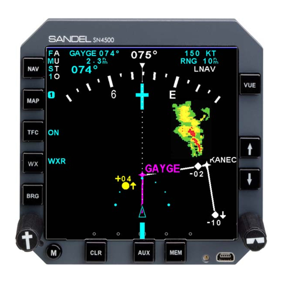
- Page 3 SN4500 Primary Navigation Display with Reversionary Attitude Mode LNAV Roll Steering Pilot’s Guide...
- Page 4 (This page intentionally left blank) 82009-PG, REV F SANDEL SN4500 PILOT’S GUIDE PAGE...
-
Page 5: Copyright
Pilot information Publication Date: 05-SEP-2012 This guide provides information on the use and operation of the SN4500 Primary Navigation Display. Information in this manual is current as of publication or revision date. Specifications and operational details are subject to change without notice at the discretion of Sandel Avionics, Inc. -
Page 6: Operational And Legal Issues
Note: Because aircraft vary in their installed equipment, it is important to note that what is displayed on the SN4500 may vary depending on the presence or absence of equipment. Please keep in mind that it is required by Federal Aviation Regulations to have on board current charts appropriate to the flight. -
Page 7: Approvals
Environmental (Categories listed in Chapter 13) DO-178B: Software Level C DO-254: Hardware Level C Installation of the SN4500 in a type-certificated aircraft must be performed in accordance with the Sandel SN4500 Installation Manual, document number 82009-IM applicable revision. 82009-PG, REV F SANDEL SN4500 PILOT’S GUIDE... -
Page 8: Conventions Used In This Manual
For example, “…press the [VUE] selection button to …” This manual uses terms, which should be familiar to aviation-minded readers, such as “selected radial” and “magnetic heading”. Terms, which are specific to the SN4500, will be placed in the glossary. 82009-PG, REV F SANDEL SN4500 PILOT’S GUIDE... -
Page 9: Table Of Contents
Revision notice Operational and legal issues Approvals Conventions Used in This Manual Table of Figures Effectivity, Revision and Errata History CHAPTER 1 WELCOME TO THE SN4500 What is the SN4500 CHAPTER 2 DISPLAY OVERVIEW SN4500 Physical Features Display Areas Indicators... - Page 10 Getting Started - Example Map Setup Map Memory Settings Storing Settings into Preset Memories 1-4 Removing a Map Memory from the Rotation Sequence Restoring Default Settings 7-10 Copying Map Settings into the Scratchpad 7-11 82009-PG, REV F SANDEL SN4500 PILOT’S GUIDE PAGE VIII...
- Page 11 12-2 Reversionary Mode Controls 12-3 Reversionary Mode Control Description 12-3 Attitude Display Details 12-4 Roll Index 12-4 Sky Pointer 12-4 Slip/Skid Indicator 12-5 Pitch Scale 12-5 Unusual Attitudes 12-6 Down Chevrons 12-6 82009-PG, REV F SANDEL SN4500 PILOT’S GUIDE PAGE...
-
Page 12: Table Of Figures
Table of Figures Figure 2-1 SN4500 Physical Features Figure 2-2 Display Areas Figure 3-1 Introduction Screen Figure 3-2 SN4500 Display with Compass Card Figure 3-3 NAV Source Annunciations Figure 3-4 Full View Figure 3-5 Arc View Figure 3-6 AUTO/MANUAL Brightness Control Selection... - Page 13 Figure 8-11 Visible Moisture Observed Figure 8-12 No Visible Moisture Observed Figure 8-13 Between Layers 8-10 Figure 9-1 SN4500 with Traffic Figure 9-2 Traffic with Moving Map Figure 9-3 ON AUTO Menu Figure 9-4 Altitude Range Menu Figure 9-5 Altitude as Flight Level Menu...
-
Page 14: Effectivity, Revision And Errata History
Applies to: SN4500 Software 2.05 SN4500 Pilot’s Guide 82009-PG, Revision F With the exception of the superseding information contained in this section, operation of the SN4500 is as described in the SN4500 Pilot’s Guide referenced above. Revision History Revision Date Comments Updated for software version 2.05... - Page 15 Figure 11-1: added callout for VOR TO/FROM arrow. Updated for software version 2.01 • Page III: Pub/Copyright date 25-MAR-2010 • TOC: updated • Page X1: Effectivity updated. 22-JAN-2009 Updated for software version 2.00 82009-PG, REV F SANDEL SN4500 PILOT’S GUIDE PAGE XIII...
- Page 16 Illustrations updated to reflect new data color coding. • Page 9-4: GPS “INTG” annunciator added. AR 867: Commercial release with 08-NOV-2006 software v1.01 16-FEB-2006 Initial Release No errata applicable to this release. 82009-PG, REV F SANDEL SN4500 PILOT’S GUIDE PAGE...
-
Page 17: Chapter 1 Welcome To The Sn4500
SN4500 will configure itself accordingly. In addition, an internal recorder can be enabled that will record up to the last 10 hours of flight data. This data can be used by Sandel to assist in troubleshooting. - Page 18 WELCOME TO THE SN4500 (This page intentionally left blank) 82009-PG, REV F SANDEL SN4500 PILOT’S GUIDE PAGE...
-
Page 19: Chapter 2 Display Overview
DISPLAY OVERVIEW CHAPTER 2 DISPLAY OVERVIEW SN4500 Physical Features The SN4500 physical layout consists of a full four inch display, twelve backlit pushbuttons, two knobs with push to select, a power on indicator, and one USB connector. Navigation Chapters 3, 4... -
Page 20: Indicators
Lubber line [white]: Points to the magnetic heading. It is always at the top of the display. Heading bug [orange or white]: This can be set to a desired heading by rotating the Heading Select knob (right knob). 82009-PG, REV F SANDEL SN4500 PILOT’S GUIDE PAGE... - Page 21 If the HDG knob is turned more than a single click an outlined heading bug will appear as a visual reference preset only. It does not connect to the SN4500 HDG output until LNAV is cancelled. LNAV operation is detailed in chapter 5.
- Page 22 – this is referred to as the outer CDI and outer VDI. There are two shapes of outer CDI and VDI pointers that can be configured during installation – bar or triangle. 82009-PG, REV F SANDEL SN4500 PILOT’S GUIDE PAGE...
- Page 23 The label “BC” will appear above the CDI and a yellow “X” will block the outer VDI during a back course approach as a reminder to the pilot as shown in the adjacent figure. 82009-PG, REV F SANDEL SN4500 PILOT’S GUIDE PAGE...
-
Page 24: Data Color Coding
DISPLAY OVERVIEW Data Color Coding Data displayed on the SN4500 is color coded as follows: Color Data displayed • Information associated with the primary VHF NAV1 receiver (or NAV2 if in co-pilot configuration) GREEN • GPS annunciators: LP, LPV, L NAV, LVNAV ACTV, AUTO and LEG •... - Page 25 (NAV2 if in the pilot configuration, NAV1 if in the co-pilot configuration) • Restricted and warning areas YELLOW • Flag indicating invalid glide slope • Marker test • Decluttered map status icons • LNAV ARMED annunciator 82009-PG, REV F SANDEL SN4500 PILOT’S GUIDE PAGE...
- Page 26 LOC1 / LOC2 Indicator • ILS1 / ILS2 Indicator • LNAV annunciator • ORANGE Heading bug and associated data (when configured to orange during installation). • BLUE Outer marker indicator • PURPLE 82009-PG, REV F SANDEL SN4500 PILOT’S GUIDE PAGE...
-
Page 27: Chapter 3 Basic Operation
Configuring the SN4500 refers to selecting the data for a given display. For example, either the VOR or the GPS receiver can drive a bearing pointer. Controlling the SN4500 refers to tailoring the display to suit the immediate situation. For example, the pilot may decide to turn off a bearing pointer completely during the enroute portion of the flight and use it only during an approach. -
Page 28: Selecting The Data
Sensor data is data that comes from avionic sources within the aircraft. This includes primary navigational instruments as well as sensors. The SN4500 can display data from the following sources: • Compass system (directional gyro and fluxgate) • NAV1 and NAV2 receivers •... -
Page 29: Selecting The Primary Nav Source
The SN4500’s course pointer and CDI can be driven from VOR or GPS data. In some installations, the [NAV] button on the SN4500 is used to select the primary NAV source. In others, an external switch performs this function and the [NAV] button has no effect. Refer to the Aircraft Flight Manual Supplement for the details of the installation. -
Page 30: Selecting And Displaying Bearing Pointers 1 & 2
Map data consists of flight plan waypoints from the LNAV receiver (GPS/FMS), as well as nearby airports, navaids, intersections and airspace from the SN4500’s internal database. The different categories of map information can be enabled or disabled individually. To display the map data, press [MAP] to cycle through the available map memory locations. -
Page 31: 360-Degree Full View And 70-Degree Arc View
Auto-Slewing the Course Pointer One unique feature of the SN4500 is its ability to automatically rotate the course pointer to the desired course being sent digitally from the GPS/FMS. This feature is called “auto-slew”, and is especially useful when flying a complex flight plan as it eliminates the burden of manually setting the course pointer for each leg of the flight plan. -
Page 32: Remote Course And Heading Knobs
The auto-slew function is enabled/disabled in the NAV menu as described in Chapter 4. Remote Course and Heading Knobs The SN4500 supports the use of remote course select and heading select knobs. When using a remote course select knob, the course select knob on the SN4500 will be disabled. -
Page 33: Display Brightness (Internal Brightness Control)
If it is desired to balance the display brightness level with other aircraft instruments, pull out and rotate the right knob until the desired brightness level is achieved. The label “TRM” and a value 82009-PG, REV F SANDEL SN4500 PILOT’S GUIDE PAGE... -
Page 34: Button Brightness
Press the knob in to return to normal operation. Figure 3-8 External Brightness Trim Control The SN4500 will revert to internal brightness control after detecting a broken connection between the display and the external brightness cockpit lighting control. In this condition Press and hold [CLR] will steadily ramp up the display brightness without requiring entry into any menus. - Page 35 BASIC OPERATION After this setting is made, the button brightness will track the display brightness regardless of how it is configured (Internal - AUTO/MAN or External – AUTO/MAN). 82009-PG, REV F SANDEL SN4500 PILOT’S GUIDE PAGE...
- Page 36 BASIC OPERATION (This page intentionally blank) 82009-PG, REV F SANDEL SN4500 PILOT’S GUIDE PAGE 3-10...
-
Page 37: Chapter 4 Nav Operation
GPS Mode Selection GPS/FMS units can be set for automatic or manual sequencing of waypoints in the active flight plan. This can be set on the SN4500 through the NAV Menu or may be available on an external switch. The GPS Mode selection will not be shown if the GPS/FMS interface does not require an external switch for mode selection. -
Page 38: Gps Appr Switch
• Press the right knob to toggle the setting between “AUTO” and “HOLD”. (Note: The terminology may differ according to the model of GPS/FMS interfaced to the SN4500.) • Press [M] to exit the menu and return to normal operation. -
Page 39: Course Pointer Display Function
Rotate the left knob until “CRS PTR” is highlighted in the far left column. • Rotate the heading bug knob to select the desired option. • Press [M] to exit the menu and return to normal operation. 82009-PG, REV F SANDEL SN4500 PILOT’S GUIDE PAGE 4-3... -
Page 40: Gps Integ / Waas Annunciations
LP, LPV, L NAV, LVNAV. Any time one of the GPS annunciators changes, it will blink for five seconds. GPS INTEG & WAAS Approach Type Annunciators Figure 4-6 Location of INTEG & WAAS Approach Annunciators 82009-PG, REV F SANDEL SN4500 PILOT’S GUIDE PAGE 4-4... -
Page 41: Figure 4-7 Gps Waas Annunciator Descriptions
The “INTEG” annunciator will always take priority over the approach type annunciators. Lateral Precision Approach Lateral Precision Approach with Vertical Guidance Lateral Navigation with Vertical Guidance Approach Lateral Navigation Approach Figure 4-7 GPS WAAS Annunciator Descriptions 82009-PG, REV F SANDEL SN4500 PILOT’S GUIDE PAGE 4-5... - Page 42 NAV OPERATION (This page intentionally blank) 82009-PG, REV F SANDEL SN4500 PILOT’S GUIDE PAGE 4-6...
-
Page 43: Chapter 5 Lnav / Roll Steering
This function will exceed the course intercept and tracking capability of the autopilot’s typical “NAV” function. When enabled, the LNAV roll steering function is an extension of the of the SN4500 heading bug function. NOTE: This capability is only available during GPS navigation. -
Page 44: Intercepting An Active Leg (Lnav Arm)
In LNAV ARM a virtual waypoint is formed at the intercept where the dotted track line crosses the active leg. This virtual waypoint is used by the SN4500 to calculate the turn anticipation point when LNAV ARM will switch to LNAV. This will provide a turn that smoothly joins the active leg in the direction of the active waypoint. -
Page 45: No Intercept" Message
HDG knob is turned more than a single click an outline heading bug will appear as a visual reference preset only. It does not connect to the SN4500 HDG output until LNAV is cancelled. The heading bug digits will be shown at the lower right of the display. -
Page 46: Flying A Gps Transition To Loc/Ils
HDG output of the SN4500. The heading bug will be at the current heading, or in the case of a preset, it will remain at the preset position. The GPS Steering command is disconnected from the HDG output. -
Page 47: Heading Bug Depiction Summary
Reminder for Pilot to select the approach mode on the APFD. Occurs when vertical guidance is provided by the GPS in LPV approaches or during LNAV operation when switching to an ILS. 82009-PG, REV F SANDEL SN4500 PILOT’S GUIDE PAGE 5-5... - Page 48 BEARING POINTERS (This page intentionally blank) 82009-PG, REV F SANDEL SN4500 PILOT’S GUIDE PAGE 5-6...
-
Page 49: Chapter 6 Bearing Pointers
NAV source. The tail of each pointer indicates the bearing from the NAV source. Either pointer can be driven by any navigation source interfaced to the SN4500: VOR, GPS/FMS, or ADF. When a GPS/FMS is selected as the bearing pointer source, the bearing pointer indicates the bearing and distance to the current active waypoint. -
Page 50: Brg Menu
Rotate the left knob to select BRG1 or BRG2 in the left column. • Rotate the right knob to select the desired option. • Press [M] to exit the menu and return to normal operation. 82009-PG, REV F SANDEL SN4500 PILOT’S GUIDE PAGE 6-2... -
Page 51: Chapter 7 Map Operations
For instance, when cruising at FL180 or higher, you might want to display only high-altitude VORs, Special Use Airspace and airports with paved runways of 6,000 feet or longer. The SN4500 allows you to save such a map configuration in one of four map memories and then recall it as needed. -
Page 52: Internal Database
MAP OPERATIONS Note: The SN4500 requires a connection to a GPS/FMS receiver in order to display the moving map. The map display, including the flight plan from the GPS1 receiver, will also be shown when NAV1 or NAV2 is selected as the primary NAV source. -
Page 53: Map Memories
1, 2, 3, 4 or S. Any memory that is empty is skipped during the MAP rotation sequence. In the default setup of the SN4500, memories 1, 2 and 3 contain default settings, and memories S and 4 are empty. -
Page 54: Map Database Items
There are a large number of selection items. However, the organization of the SN4500 is intended to make the map setup process as easy as possible. You should experiment with the map settings until you develop the style of operation best suited for your flying. -
Page 55: Getting Started - Example
Prohibited airspace is always displayed when in range and cannot be disabled. Getting Started - Example The default SN4500 map memories are set up as follows: S: Empty 1: GPS/FMS flight plan... -
Page 56: Map Setup
All settings in map memory 1 are coped to S (the scratchpad memory), and you can now make non-permanent changes using the knobs. Changes are actually made to the scratchpad memory S. To 82009-PG, REV F SANDEL SN4500 PILOT’S GUIDE PAGE 7-6... -
Page 57: Figure 7-2 Map Setup Menu
• Rotate the left knob until “MENU SEL” in the far left column is highlighted. • Rotate the right knob until airspace is highlighted as shown below: Figure 7-3 Select "AIRSPC" 82009-PG, REV F SANDEL SN4500 PILOT’S GUIDE PAGE 7-7... -
Page 58: Map Memory Settings
Rotate the right knob until “MEMORY” in the far right column is highlighted. Storing Settings into Preset Memories 1-4 • Rotate the left knob until “S COPY TO” in the far left column is highlighted. 82009-PG, REV F SANDEL SN4500 PILOT’S GUIDE PAGE 7-8... -
Page 59: Removing A Map Memory From The Rotation Sequence
Rotate the left knob to highlight “CLEAR” Figure 7-6 Removing Map Memory • Map memory "CLEAR" • Rotate the right knob to select the desired map memory location to be cleared. 82009-PG, REV F SANDEL SN4500 PILOT’S GUIDE PAGE 7-9... -
Page 60: Restoring Default Settings
Selecting “ALL” will restore all of the map memory locations to default settings. • Press [M] to exit the menu and return to normal operation. 82009-PG, REV F SANDEL SN4500 PILOT’S GUIDE PAGE 7-10... -
Page 61: Copying Map Settings Into The Scratchpad
Automatic Decluttering Occasionally, the SN4500 map display may become too cluttered to read, such as by turning on several categories of map items. The SN4500 will automatically remove items from the display if the total number of items is too great to display. When this occurs, it is indicated by an icon color... -
Page 62: Maximum Range Of Internal Map Data
MAP OPERATIONS Normally the SN4500 will allow up to approximately 50 icons before this action occurs, but this number may be smaller if complex airspace is displayed simultaneously. When automatic decluttering occurs, it occurs first to objects closest to the aircraft. When the display is zoomed-in, these objects will reappear and the associated status bar icon will turn back to cyan. -
Page 63: Chapter 8 Weather Display Interface
WX-500 Stormscope® Data If an L-3 WX-500 Stormscope lightning detection sensor has been installed in the aircraft, it can be configured to display on the SN4500 as shown on Figure 8-1. Lightning strikes are displayed in the SN4500’s primary display area, and are automatically synchronized with the aircraft’s heading. -
Page 64: Figure 8-2 Wx Setup Menu
Enables display of WX-500 strikes in CELL mode, CELL which displays a lightning symbol for each group of strikes. : Enables display of WX-500 strikes in STRIKE STRK mode, which displays a lightning symbol for each individual strike. 82009-PG, REV F SANDEL SN4500 PILOT’S GUIDE PAGE 8-2... -
Page 65: Fis-B Datalink Weather
Display only strikes from WSI. BOTH: Display strikes from WX-500 & WSI. FIS-B Datalink Weather The SN4500 displays Flight Information Services-Broadcast (FIS-B) weather information when connected to a WSI InFlight data link receiver 82009-PG, REV F SANDEL SN4500 PILOT’S GUIDE... -
Page 66: General Operation
WEATHER DISPLAY INTERFACE and the SN4500 contains software version 1.03 or above enabled with the Datalink Weather option. The particular FIS-B products (CONUS only) supported in the SN4500 are: • Precipitation • Lightning Figure 8-6 FIS-B Weather Display General Operation... -
Page 67: Precipitation Intensity
Three color shades are used to represent strike aging per Figure 8-8. Figure 8-8 FIS-B Lightning Strike Age After 15 minutes, the strike is removed from the screen. 82009-PG, REV F SANDEL SN4500 PILOT’S GUIDE PAGE 8-5... -
Page 68: Fis-B Services Backgrounder
• To cue the pilot to communicate with the Air Traffic Control controller, Aircraft Flight Service station specialist, operator, dispatch, or airline operations control center as required. 82009-PG, REV F SANDEL SN4500 PILOT’S GUIDE PAGE 8-6... -
Page 69: Figure 8-9 Fis-B Information Flow
By the time this information is received in the aircraft and displayed on the SN4500, it will be aged from 3 to 11 minutes depending on the amount of data transmitted. This process is repeated at approximately 5 minutes intervals. -
Page 70: Examples
The reception age uses the time the tile is received from the aircraft receiver by the SN4500. The SN4500 displays to the right of the WX button the time in minutes since any mosaic tiles have been received. -
Page 71: Figure 8-11 Visible Moisture Observed
Figure 8-12 No Visible Moisture Observed Most likely, a flight crew will recognize the cloud deck below and consider that the conditions represented on the SN4500 in Figure 8-10 are well below the aircraft. However, it may not be so apparent when flying between cloud layers as Figure 8-13 illustrates. -
Page 72: Figure 8-13 Between Layers
FIS-B system has malfunctioned while as the figure shows the serious weather is below the aircraft further illustrating the lack of vertical information provided with the FIS-B weather system. Figure 8-13 Between Layers 82009-PG, REV F SANDEL SN4500 PILOT’S GUIDE PAGE 8-10... -
Page 73: Chapter 9 Traffic Display Interface
Pilot’s Guide for the specific traffic system installed in the aircraft for a complete description of the capabilities. Note: The SN4500 can be interfaced to a TCAS II processor but will function only as a traffic display as vertical guidance information required for conflict resolution will not be displayed. -
Page 74: Relative Altitude
Relative Altitude Relative altitude in hundreds of feet and vertical trend information are also given for each target aircraft. Note: Values greater than 9900 feet are shown as ‘99’. 82009-PG, REV F SANDEL SN4500 PILOT’S GUIDE PAGE 9-2... -
Page 75: Absolute Altitude Vs. Relative Altitude
The traffic display mode is annunciated next to the [TFC] button. There are three different modes available which control how the targets are displayed on the SN4500 and are toggled by pressing the [TFC] button. Enables display of all targets within the selected map range. -
Page 76: Altitude Mode
[TFC] button. The Traffic Display Mode annunciation will also be lined out in red. TEST: TCAS is currently in Test mode OFF or STBY: TCAS is currently in Standby mode FAIL: TCAS data communication not present 82009-PG, REV F SANDEL SN4500 PILOT’S GUIDE PAGE 9-4... -
Page 77: Traffic Overlay With Moving Map
The traffic setup menu will be displayed. The following options are available: • ON AUTO: Enables or disables map auto-ranging when alerting traffic is displayed and the traffic display mode is set to ON. 82009-PG, REV F SANDEL SN4500 PILOT’S GUIDE PAGE 9-5... -
Page 78: Figure 9-3 On Auto Menu
ALT AS FL (Ryan 9900BX/Avidyne 600 Series TAS Only): Changes the altitude of target aircraft to be shown as absolute altitude instead of relative altitude for 30 seconds. Figure 9-5 Altitude as Flight Level Menu 82009-PG, REV F SANDEL SN4500 PILOT’S GUIDE PAGE 9-6... -
Page 79: Chapter 10 Flags And Abnormal Conditions
FLAGS AND ABNORMAL CONDITIONS CHAPTER 10 FLAGS AND ABNORMAL CONDITIONS The SN4500 detects abnormal conditions such as flagged navigation receivers and failed directional gyro or fluxgate. It also monitors its own internal temperature and provides warnings for over temperature or loss of cooling conditions. - Page 80 Directional gyro Compass rose color changes failure from white to amber. Heading data is obtained from fluxgate alone if connected to SN4500. Because fluxgate signals are averaged over time, heading response will lag the aircraft significantly. Fluxgate failure Compass rose color changes from white to amber and the Loss of gyro &...
- Page 81 GPS/FMS flag Redlined GPS/FMS at upper left indicates loss of data from the receiver. Map flag Redlined map icons indicate that the map cannot be displayed because of loss of LNAV. 82009-PG, REV F SANDEL SN4500 PILOT’S GUIDE PAGE 10-3...
- Page 82 Stormscope display has been temporarily suppressed due to the presence of a traffic alert. Traffic flag Redlined “ON”, “A” or “M” next to TFC button indicates loss of data communication from the traffic processor. 82009-PG, REV F SANDEL SN4500 PILOT’S GUIDE PAGE 10-4...
- Page 83 Approach Type primary means of navigation Annunciation must be used. When a WAAS approach is selected and “INTEG” is not displayed, the WAAS approach type (LP, LPV, L NAV, LVNAV) will display. 82009-PG, REV F SANDEL SN4500 PILOT’S GUIDE PAGE 10-5...
- Page 84 FLAGS AND ABNORMAL CONDITIONS (This page intentionally blank) 82009-PG, REV F SANDEL SN4500 PILOT’S GUIDE PAGE 10-6...
-
Page 85: Chapter 11 Messages
MESSAGES CHAPTER 11 MESSAGES The Sandel SN4500 displays different messages to alert the pilot. The messages are initiated by the Pilot, the Built in Self Test (BIST), the Power On Self Test (POST), or by the system. Most of the pilot initiated messages are shown for two seconds and are removed automatically. - Page 86 As the temperature rises a warning will be issued prior to shutdown. If shutdown occurs the SN4500 will shut off the projection lamp and continue operating, and resume normal operation as the internal temperature falls.
- Page 87 MESSAGES Message Description EXT SW SET TO GPS This message appears when pressing the “NAV” button on the SN4500 when it is slaved external GPS/NAV switch/annunciator panel. Instead of the SN4500 NAV switch use the external GPS/NAV switch. EXT SW SET TO NAV...
- Page 88 ARINC-429 heading source has been configured with a fluxgate (ARINC-429 heading inputs may not be slaved). INTERNAL FAULT Internal fault on the SN4500 which will require service. UNIT MUST NOT BE USED NAVIGATION THIS MESSAGE APPEARS.
- Page 89 NAV SRC is not selected to GPS. NAV TUNED TO ILS This message appears when pressing the “NAV” switch on the SN4500 to select a GPS and this action is overridden because an ILS is tuned on NAV1 or NAV2 and ILS lockout was enabled during installation.
- Page 90 As the temperature rises a warning will be issued prior to shutdown. If shutdown occurs the SN4500 will shut off the backlight and continue operating, and resume normal operation as the internal temperature falls.
- Page 91 Description REMOTE CRC FAULT Settings in the configuration module contain an error. RMT-COURSE Course knob on SN4500 disabled due to ACTIVE connection of remote course knob. USE OBS ON GPS Adjust OBS on GPS navigator. OBS, including remote CRS knob if equipped, is disabled locally per installation selection.
- Page 92 MESSAGES (This page intentionally blank) 82009-PG, REV F SANDEL SN4500 PILOT’S GUIDE PAGE 11-8...
-
Page 93: Chapter 12 Reversionary Attitude Mode
CHAPTER 12 REVERSIONARY ATTITUDE MODE The SN4500 with software version 2.00 or later includes a Reversionary Attitude Mode capability. This feature, if installed, may be used as backup attitude in the event of loss of the primary attitude display. When activated,... -
Page 94: Reversionary Mode Display Description
Reversionary Mode Display Description The Reversionary Mode incorporates some of the standard navigation display elements from the SN4500 HSI display overlaid on top of an attitude display with a roll index, sky pointer and slip-skid indicator. Refer to Chapter 2 of this guide for a detailed description of the navigation display elements. -
Page 95: Reversionary Mode Controls
Momentarily displays HSI showing MAP memory 1 MAP: with traffic in Auto. Momentarily displays HSI showing MAP memory 1 TFC: with traffic ON. The display will auto range only if a TA or RA is if active. 82009-PG, REV F SANDEL SN4500 PILOT’S GUIDE PAGE 12-3... -
Page 96: Attitude Display Details
Displays the aircraft roll attitude. angle at 10°, 20°, 30°, 45°, and 60°. NOTE: The sky pointer always Sky Pointer – Shows the points UP, away from the center of current roll attitude. the earth. 82009-PG, REV F SANDEL SN4500 PILOT’S GUIDE PAGE 12-4... -
Page 97: Slip/Skid Indicator
0° to 90° relative to the pitch reference point. Scale is marked in increments of 2.5°. Pitch-down attitudes are preceded by a minus sign. 82009-PG, REV F SANDEL SN4500 PILOT’S GUIDE PAGE 12-5... -
Page 98: Unusual Attitudes
FUNCTION OPERATION Use appropriate unusual attitude Down Chevrons recovery techniques to resume normal Downward pointing red flight. chevrons appear whenever the upward pitch attitude exceeds +30°. 82009-PG, REV F SANDEL SN4500 PILOT’S GUIDE PAGE 12-6... -
Page 99: Up Chevrons
REVERSIONARY DISPLAY FUNCTION OPERATION Up Chevrons Use appropriate unusual attitude recovery techniques to resume normal Upward pointing red flight. chevrons appear whenever the downward pitch attitude exceeds -20°. 82009-PG, REV F SANDEL SN4500 PILOT’S GUIDE PAGE 12-7... -
Page 100: Reversionary Mode Annunciations
RA. Pressing the TFC pushbutton will momentarily show traffic display HSI will display in FULL mode HSI Vue Preview HSI will display in ARC mode HSI Range will display Preview indicated range 82009-PG, REV F SANDEL SN4500 PILOT’S GUIDE PAGE 12-8... - Page 101 Form Factor: 4-ATI (ARINC 408) Width: 3.970 in. (10.1 cm.) Height: 3.970 in. (10.1 cm) Length: 9.27 in. (23.5 cm.) from panel to back of unit Weight: 3.5 lbs. (1.6 kg.) 82009-PG, REV F SANDEL SN4500 PILOT’S GUIDE PAGE 13-1...
- Page 102 -20º C to + 70º C 55,000 ft. maximum altitude Power Inputs: 22 to 33 VDC 1.4 Amperes nominal @ 27.5 VDC 400 HZ Reference: 26 volts nominal, less than 1 milliampere load 82009-PG, REV F SANDEL SN4500 PILOT’S GUIDE PAGE 13-2...
-
Page 103: Chapter 14 Installation Information
Date of Installation: _____________________________________ Installer Company: _____________________________________ Installer Address: ______________________________________________________ ______________________________________________________ ______________________________________________________ Installer Phone: ________________________________________ Work Order #: __________________________________________ Installer: ______________________________________________ NAV Equipment Inputs: __________________________________ Notes: ______________________________________________________ ______________________________________________________ ______________________________________________________ ______________________________________________________ ______________________________________________________ 82009-PG, REV F SANDEL SN4500 PILOT’S GUIDE PAGE 14-1... - Page 104 INSTALLATION INFORMATION (This page intentionally left blank) 82009-PG, REV F SANDEL SN4500 PILOT’S GUIDE PAGE 14-2...
-
Page 105: Chapter 15 Glossary
ARC, and the aircraft’s current position, is depicted near the bottom of the display. FULL View A 360-degree FULL view where the aircraft’s current position is depicted at the center of the display. 82009-PG, REV F SANDEL SN4500 PILOT’S GUIDE PAGE 15-1... - Page 106 GLOSSARY (This page intentionally left blank) 82009-PG, REV F SANDEL SN4500 PILOT’S GUIDE PAGE 15-2...
-
Page 107: Chapter 16 Avionics Acronyms
Cyclic Redundancy Check Distance Measuring Equipment EFIS Electronic Flight Instrument System EHSI Electronic Horizontal Situation Indicator Federal Aviation Administration FIS-B Flight Information Services-Broadcast Flight Management System General Aviation Global Positioning System 82009-PG, REV F SANDEL SN4500 PILOT’S GUIDE PAGE 16-1... - Page 108 Military Operations Area Navigation Receiver (VOR) Nautical Miles Omni Bearing Selector Pilot’s Operating Handbook POST Power-On Self-Test Radio Magnetic Indicator TACAN Tactical Air Navigation System Traffic Advisory Traffic Advisory System Traffic 82009-PG, REV F SANDEL SN4500 PILOT’S GUIDE PAGE 16-2...
- Page 109 Volts AC (alternating current – in aircraft typically 400Hz) Volts DC (direct current) Vertical Deviation Indicator (for glide slope) Very High Frequency VHF Omnidirectional Radio Range VORTAC System with a co-located VOR and a TACAN station 82009-PG, REV F SANDEL SN4500 PILOT’S GUIDE PAGE 16-3...
- Page 110 AVIONICS ACRONYMS (This page intentionally left blank) 82009-PG, REV F SANDEL SN4500 PILOT’S GUIDE PAGE 16-4...
Need help?
Do you have a question about the SN4500 and is the answer not in the manual?
Questions and answers