Table of Contents
Advertisement
Quick Links
Download this manual
See also:
Installation Manual
Advertisement
Table of Contents

Related Manuals for Sandel HeliTAWS ST3400H


Summary of Contents for Sandel HeliTAWS ST3400H
- Page 1 ST3400H Helicopter Terrain Awareness Warning System Pilot’s Guide Revision B1...
- Page 2 (This page intentionally left blank) 82046-PG-B1 ST3400H PILOT’S GUIDE Page ii...
-
Page 3: Table Of Contents
TABLE OF CONTENTS 1 INTRODUCTION ................1-1 Pilot Information................1-1 Copyright ...................1-1 Revision Notice................1-1 Operational and Legal Issues .............1-2 Trademarks ................1-2 Approvals...................1-2 Conventions Used In This Manual..........1-3 Effectivity, Revision History And Errata........1-3 2 LIMITATIONS...................2-1 3 WELCOME TO THE ST3400H HELITAWS.........3-1 Description.................3-1 What it is ..................3-1 What it isn’t................3-2 What it does ................3-2 Other Features................3-3... - Page 4 No-Sensor Display ..............5-4 FULL / ARC ................5-5 REL/TOPO ................5-6 5.7.1 TOPO DETAILS..............5-6 5.7.2 REL DETAILS...............5-6 REL Color Banding ..............5-7 Display Orientation ..............5-7 5.10 Display Range................5-9 5.11 Overlay..................5-10 5.12 Heading Pointer ...............5-11 5.13 Sensitivity ................5-12 5.14 Off Airport Mode ..............5-13 5.15 Mute ..................5-14 5.16 Brightness ................5-15 5.17 Flight Plan................5-16 6 TERRAIN AND OBSTACLE ALERTING ........6-1...
- Page 5 Symbology .................9-3 Altitude Tags................9-4 9.6.1 Relative...................9-4 9.6.2 Traffic Absolute Altitude ............9-4 9.6.3 Traffic Alert Priority...............9-4 PILOT MENU................10-1 10.1 GS INHIBIT................10-1 10.2 TAWS INH ................10-2 10.3 TEST..................10-3 10.4 TCAS TEST................10-4 10.5 Traffic System Altitude Mode ..........10-5 10.6 Brightness ................10-6 10.7 System Status ................10-6 10.7.1 Equipment List ..............10-7 EXTERNAL SWITCH AND ANNUNCIATORS ....11-1...
- Page 6 TABLE OF FIGURES Figure 5-1 ST3400H Physical Features............5-1 Figure 5-2 Display Overview TOPO/FULL..........5-2 Figure 5-3 Startup Screen.................5-3 Figure 5-4 Initial Display .................5-4 Figure 5-5 FULL and ARC Views ............5-5 Figure 5-6 REL and TOPO Displays............5-6 Figure 5-7 REL Display Color Banding relative to aircraft altitude ..5-7 Figure 5-8 Display Orientation..............5-8 Figure 5-9 Display Ranging ..............5-9 Figure 5-10 Overlay Button ..............5-10...
- Page 7 Figure 10-7 Dimmer Mode..............10-6 Figure 10-8 System Status..............10-6 Figure 12-1 On-Screen Annunciation ............12-1 82046-PG-B1 ST3400H PILOT’S GUIDE Page vii...
- Page 8 (This page intentionally left blank) 82046-PG-B1 ST3400H PILOT’S GUIDE Page viii...
-
Page 9: Introduction
Patent No. 1211639C. Israel Patent Nos. 135,174, 153,460, and 155,983. All rights reserved. No part of this manual may be reproduced, stored, or distributed without written permission of Sandel Avionics, Inc. Additional copies of this manual are available from: Sandel Avionics, Inc. -
Page 10: Operational And Legal Issues
ST3400H by the associated approved GPS receiver. Supplemental data is intended for positional awareness only. Trademarks Sandel, the Sandel Logo, HeliTaws, and the HeliTaws Logo are trademarks of Sandel Avionics, Inc. Approvals The FAA has approved the ST3400H under the following TSOs: ... -
Page 11: Conventions Used In This Manual
Complex Logic: RTCA/DO-254 Level C Installation of the ST3400H in a type-certificated rotorcraft must be performed in accordance with the Sandel ST3400H Installation Manual, document number 82046-IM applicable revision. Conventions Used In This Manual The name of a button is placed within square brackets when the button is described in text. -
Page 12: Limitations
LIMITATIONS The ST3400H is an alerting system. It is intended for use in rotorcraft for all phases of flight in VMC and in IMC while operating under instrument flight rules (IFR). Due to data limitations it is NOT guaranteed that every actual terrain or obstacle conflict will produce an alert, and alerts generated may NOT guarantee successful recovery due to factors such as pilot response, aircraft performance and database limitations. -
Page 13: Welcome To The St3400H Helitaws
The ST3400H uses Sandel’s patented rear-projection display technology. This technology allows the displayed image to extend to the edges of the instrument’s bezel. Therefore, even though the Sandel display is in a 3- inch form factor, its image is approximately the size of a 4” primary display. -
Page 14: What It Isn't
What it isn’t The ST3400H is not the pilot. Remember: it is a tool, and it isn’t perfect. Neither the terrain data nor the obstacle data on which alerting is based is guaranteed to be 100% accurate, nor are the sensors feeding the system. There is no substitution for good judgment by the pilot. -
Page 15: Other Features
An internal data recorder automatically records a minimum of the last twenty hours of flight data. Oldest data is automatically overwritten with most recent data. This data can be used by Sandel Customer Support to analyze recent alert activity. Other Features Display of Radar Altitude is provided along with a MINS setter. -
Page 16: System Overview
SYSTEM OVERVIEW “Design Cruise Altitude” The ST3400H introduces the concept of “Design Cruise Altitude”. This is the nominal cruise altitude at which the ST3400H is designed to give nuisance-free alerts with a black (no terrain showing) relative altitude display. 4.1.1 Sensitivity To facilitate low altitude operations unique to helicopters, the ST3400H supports two pilot selectable alert sensitivity modes: Normal Sensitivity... -
Page 17: Taws Inhibit
(relative altitude) terrain display is automatically selected at an appropriate range to put the alerting terrain on-screen. Pilots should train to react properly to all alerts, cautions and warnings, just as one would train to react to any other potential or actual emergency situation. -
Page 18: Flight Plans
4.5.8 NVIS For missions requiring the use of night vision goggles, certain ST3400H models are equipped with Sandel’s proprietary on-demand Class-B NVIS capability. Unlike aftermarket NVIS modifications, Sandel’s unique NVIS feature employs no external filters and does not degrade its brightness or daylight characteristics when NVIS is OFF. -
Page 19: Sensors
The terrain and airport database coverage is provided by geographical area. Coverage is limited to those areas between 70N and 70S latitude. Obstacle data is included for most countries. Please contact Sandel for the most current coverage information. Note: There is no guarantee that every obstacle is charted or that every charted obstacle is in the obstacle database. -
Page 20: Terrain Display And Operation
TERRAIN DISPLAY AND OPERATION The following section describes the appearance of the ST3400H display and identifies each functional element. Control Overview The ST3400H physical layout consists of a display screen, 9 backlit buttons, one push-pull rotary knob, and one USB connector. ARC/FULL Terrain REL/TOPO View... -
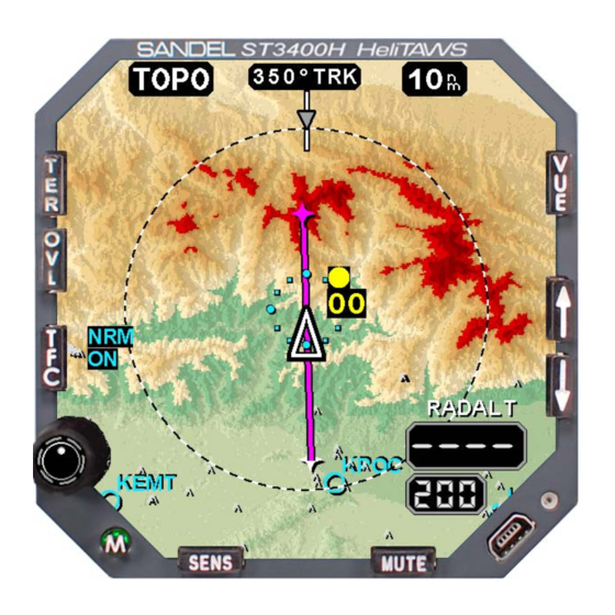
Page 21: Display Overview
Display Overview The display is composed of underlying terrain, with symbol and text overlays. The display is geometrically referenced to the tip of the symbolic aircraft Figure 5-2 Display Overview TOPO/FULL 82046-PG-B1 ST3400H PILOT’S GUIDE Page 5-2... -
Page 22: Splash Screen
Splash Screen At power-up there is no splash screen shown. The M button will light at night brightness level when power is applied, and the display will be blank for approximately 25 seconds. Initial Bootup Display After approximately 25 seconds after initial power-up, a short introduction screen will be displayed which includes software and database versions. -
Page 23: No-Sensor Display
Display No-Sensor After the power up display is removed, the operating screen will likely show sensors in the failed state until they become available: Figure 5-4 Initial Display As soon as sensor availability is established the terrain will immediately build on the screen and normal operation will start. 82046-PG-B1 ST3400H PILOT’S GUIDE Page 5-4... -
Page 24: Full / Arc
FULL / ARC Press [VUE] to switch between 360-degree and 70-degree ARC views. Figure 5-5 FULL and ARC Views This action only affects the screen display – it has no affect on alerting. The ARC view maximizes the display of the ground track ahead of the aircraft and provides the greatest amount of screen area for map data. -
Page 25: Rel/Topo
REL/TOPO Pressing the TER button will change the display from REL to TOPO. The current mode is annunciated at the top of the display. REL TOPO Figure 5-6 REL and TOPO Displays NOTE: Selecting REL/TOPO has no affect on alerting. 5.7.1 TOPO DETAILS TOPO shows all the terrain in sectional chart colors in shaded relief. -
Page 26: Rel Color Banding
REL Color Banding The REL colors graphically show the clearance between the current aircraft altitude and the terrain or obstacles. Colors depend on the selected SENSITIVITY. The following are the color band altitudes during cruise flight. Dark Red Normal or Low: > 1000 ft. above Normal: 50’... -
Page 27: Figure 5-8 Display Orientation
line shows exactly where the aircraft is going to be on its current ground track. Figure 5-8 Display Orientation TRK is used above 35Kts ground speed. HDG is used below 30Kts ground NOTE: Traffic symbols are always referenced to the nose of the aircraft, even if the display directional source is TRK. -
Page 28: Display Range
5.10 Display Range The Display Range is the distance in nautical miles between the tip of the symbolic aircraft and the dashed range ring. Switching between FULL and ARC view maintains the terrain cell size during range changes. AVAILABLE RANGES View Ranges FULL... -
Page 29: Overlay
5.11 Overlay The OVL button is reserved for a future feature. Pressing this button when in the normal display mode (not in the pilot menu) will display the message “NOT IMPLIMENTED”. Overlay Button Figure 5-10 Overlay Button 82046-PG-B1 ST3400H PILOT’S GUIDE Page 5-10... -
Page 30: Heading Pointer
5.12 Heading Pointer The Heading Pointer is the inverted gray triangle located at the top of the display when in TRK orientation. The Heading Pointer shows the magnetic heading of the aircraft (where it is pointed) and can be used for identifying the crab angle. -
Page 31: Sensitivity
5.13 Sensitivity Press the SENS button to toggle the Sensitivity between NORM and LOW. NORM has no screen annunciation. LOW displays LOW-SENS as shown in the figure. Low Sensitivity Mode Annunciator SENS Button Figure 5-13 Alert Sensitivity Selection Note: This function may also be accessed by an optional mounted pushbutton. -
Page 32: Off Airport Mode
5.14 Off Airport Mode HOLD the SENS button to toggle the OFF-APT mode. This annunciates OFF-APT in Cyan. Off-Airport Mode Annunciator SENS Button Figure 5-14 Off-Airport Mode Selection Note: This function may also be accessed by an optional mounted pushbutton. 82046-PG-B1 ST3400H PILOT’S GUIDE Page 5-13... -
Page 33: Mute
5.15 Mute An already occurring CAUTION alert may be muted for 15 seconds by pressing the MUTE button. During Caution alerts the MUTE button will highlight with a white bar as an aid to locating the mute function. Figure 5-15 MUTE Button Highlighting Notes: ... -
Page 34: Brightness
5.16 Brightness Figure 5-17 Brightness Pull the knob and turn to adjust the brightness. The brightness is shown above the knob as a number from 0-100. 100 is full brightness. 82046-PG-B1 ST3400H PILOT’S GUIDE Page 5-15... -
Page 35: Flight Plan
5.17 Flight Plan If the FMS supplies a flight plan, each flight plan segment is displayed. The active flight plan segment is colored magenta and the balance of the flight plan segments are colored white. NOTE: Display of DME arcs, Holding Patterns, and Procedure Turns is not currently supported in the ST3400H with S/W version 1.01. -
Page 36: Terrain And Obstacle Alerting
TERRAIN AND OBSTACLE ALERTING Alert Generation FLTA is an acronym for Forward Looking Terrain Alerting. The FLTA Alerting Area is an area mostly in front of and to both sides of the aircraft. Through sophisticated look-ahead algorithms, alerts are generated if terrain or an obstacle conflict with the path of the aircraft. -
Page 37: Figure 6-2 Terrain Alert Flying Toward Obstacle - Level Flight
Cautions are always designed to occur prior to warnings during steady- state flight. There are exceptions such as initiating turns into terrain or initiating a descent when close to terrain. Under these conditions a Warning may be received without a Caution. In some cases, a terrain alert may be issued while flying toward an obstacle. -
Page 38: Alert Display
Alert Display When an alert occurs, REL is automatically selected, in ARC view, at an appropriate range to put the conflict on the screen. After the alert occurs the pilot may select other display modes (such as TOPO) and/or other ranges if desired. -
Page 39: Alert Circle
An AMBER CAUTION annunciation and requires immediate pilot attention. A RED WARNING annunciation and requires immediate aggressive pilot action. Pilot reactions to alerts and warnings differ according to weather conditions, visibility, type of warnings, phase of flight, and aircraft performance considerations. -
Page 40: Obstacle Symbology
Figure 6-5. Figure 6-5 Obstacle Alert on a tall tower Obstacle Symbology Obstacles are depicted by two symbols. These symbols will be sized according to the relative height below the helicopter and the distance. There is no difference in meaning between the same symbol depicted at different sizes. -
Page 41: Figure 6-7 Obstacles In Topo Display
display that are below the REL GRN color band. Any obstacles above the current helicopter altitude are shown in red. All other obstacles are shown sized and highlighted to indicate their proximity to the helicopter. Note that obstacles far from the helicopter are shown very small - for situational reference / planning only. -
Page 42: Obstacles In Rel Display
6.6.2 Obstacles in REL Display The following figures who the same situation as Figure 6-7 after pressing the TER button. REL mode only obstacles near the helicopter altitude where RED/YEL/GRN color coding is enforced. The obstacles below the ‘green’ altitude drop out of the display completely. Figure 6-9 Obstacles in REL Display Figure 6-10 Obstacles in REL Display Figure 6-10 is the same as Figure 6-9 except with the helicopter at a... -
Page 43: Taws Inhibit - Flta
A perceived nuisance alert, or an alert expected but not received, should be brought to the attention of Sandel Avionics for analysis. Be aware that the TAWS INH function cancels all alerts - FLTA and GPWS. Altitude Callouts remains active, and terrain is removed from the screen. -
Page 44: Gpws Alerting
GPWS ALERTING The ST3400H contains a Ground Proximity Warning System separate from the FLTA alert system. The GPWS is a downward looking alert capability which generally uses the radar altimeter as an alerting source. The GPWS alerts could be considered as a backup system if FLTA was not available (such as if GPS position was unavailable) or the helicopter was hovering. -
Page 45: Mode 4 - Landing Gear
Mode 4 – Landing Gear For retractable gear aircraft - A “TOO LOW GEAR” Caution Alert is generated if the aircraft descends below 125’ while in the Normal Sensitivity mode (or below 50’ while in the Low Sensitivity mode) and the landing gear is not down. -
Page 46: Taws Inh - Gpws
TAWS INH - GPWS GPWS alerting, can be inhibited with the TAWS INH function. The TAWS INH function also cancels all FLTA alerts. When TAWS INH is active, Callouts remains active. Figure 7-5 TAWS INHIBIT 82046-PG-B1 ST3400H PILOT’S GUIDE Page 7-3... -
Page 47: Radar Altimeter Functions
RADAR ALTIMETER FUNCTIONS The ST3400H functions as a Radar Altimeter indicator when interfaced to a compatible Radar Altimeter system. A Radar Altitude display and a MINS setting window are provided. The Radar Altitude will not be displayed if a Radar Altimeter is not installed. -
Page 48: Traffic Function
TRAFFIC FUNCTION Traffic Display Figure 9-1 ST3400 Traffic Overlay Traffic will be overlaid on terrain when in REL and TOPO display views. The traffic is always shown relative to the nose of the aircraft – where you would see it if you looked out the window. The [TFC] button is used to control the display of traffic data from nearby transponder equipped aircraft when the ST3400H is interfaced with a compatible TAS, TCAS, or ADS-B processor. -
Page 49: Traffic Processor Altitude Mode
display of traffic all the time may cause the screen to become too cluttered. Note: The traffic alert and its audio are provided by the TAS or TCAS system, not the ST3400H. Traffic Processor Altitude Mode The traffic processor’s altitude display mode will be displayed above the TFC Display Mode indicator. -
Page 50: Symbology
Symbology The ST3400H uses standard RTCA symbology to represent traffic. Alerting Traffic DISPLAY CONDITION DESCRIPTION Immediate threat that requires evasive action. Resolution Advisory Note: Vertical guidance (RA) (Available with information is NOT TCAS II Only) shown on the ST3400H display. Traffic within 15-30 seconds of closure, or Traffic Advisory... -
Page 51: Altitude Tags
Altitude Tags 9.6.1 Relative Relative altitude in hundreds of feet and vertical trend information are given for each target aircraft. Note: Values greater than 9900 feet are shown as ‘99’. The ‘-02’ indicates the target is 200 feet below your current aircraft altitude. -
Page 52: Pilot Menu
10 PILOT MENU Press the [M] “Menu” button to access the Pilot Menu. Figure 10-1 Pilot Menu 10.1 GS INHIBIT [GS] soft key controls GPWS Mode 5 glide slope alerts NORM or INH (disabled). When in INH the glide slope warning is disabled. Note: The Mode 5 alert is also automatically disabled when flying a back course approach, if this capability is installed. -
Page 53: Taws Inh
A perceived nuisance alert should be brought to the attention of Sandel Avionics for analysis. Be aware that the TAWS INH function cancels all FLTA alerts and inhibits GPWS modes 1, 3, 4, and 5. When TAWS INH is active, Altitude Callouts remain active. -
Page 54: Test
10.3 TEST The [TEST] softkey performs the following functions. Tests external annunciator lamps, if installed. Tests on-screen annunciation of CAUTION followed by WARNING. Tests audio system with CAUTION followed by WARNING audio. This test should be performed before each flight. TEST Figure 10-4 TEST 82046-PG-B1... -
Page 55: Tcas Test
10.4 TCAS TEST Provides a TCAS TEST output discrete for BFG traffic systems. Press the knob to perform the TCAS TEST. Consult the Rotorcraft Flight Manual Supplement for the ST3400H installation for you aircraft and the traffic system pilot’s guide for additional details. Figure 10-5 TCAS Test 82046-PG-B1 ST3400H PILOT’S GUIDE... -
Page 56: Traffic System Altitude Mode
10.5 Traffic System Altitude Mode The ST3400H supports four altitude filtering modes: NORM (Normal), ABOVE, BELOW, and XTNDD (Extended). Depending on the model of traffic system interfaced to the ST3400H in your particular installation, these altitude filtering modes may be controllable through this soft key. Descriptions for these modes can be found in Chapter 6 –... -
Page 57: Brightness
10.6 Brightness Manual Brightness is the only mode that is currently supported by the ST3400H. Dimmer Mode Figure 10-7 Dimmer Mode 10.7 System Status The System Status box contains a list of failed or inoperative equipment. The UP/DOWN Arrow buttons can be used to scroll through messages. Figure 10-8 System Status 82046-PG-B1 ST3400H PILOT’S GUIDE... -
Page 58: Equipment List
10.7.1 Equipment List INVALID/FAILED EQUIPMENT LIST Input Description Air Data Computer Autopilot engaged input inop TAWS INH Taws Inhibit input inop GPS/Flight Management System input GPS/Flight Management System input GEAR Landing Gear INOP (ARINC 429 only) Glideslope Receiver Heading System, AHRS or Directional Gyro Localizer Receiver Radio Altimeter 82046-PG-B1... -
Page 59: External Switch And Annunciators
11 EXTERNAL SWITCH AND ANNUNCIATORS External annunciators and switches may be optionally installed. The supported external annunciators are: TAWS illuminates in amber whenever an amber caution is present on the ST3400H display. TAWS illuminates in red whenever a red warning is present on the ST3400H display. -
Page 60: On Screen Annunciations
12 ON SCREEN ANNUNCIATIONS Figure 12-1 (below) is an illustration of the various position and meanings of on-screen annunciations: GPWS FAIL: One or more GPWS modes are unavailable due to failed equipment, typically Radar Altimeter failure. GS INH: Glide Slope Inhibit active. No glide slope alerts will occur. - Page 61 These messages are displayed during Pilot’s Menu test: ALERT TEST Text Message Type TEST CAUTION Caution TEST WARNING Warning ADVISORY MESSAGES REQUIRING ACKNOWLEDGE Text Message Description Comment 1.5V PWR SUPPLY 1.5 Volt power supply Report to Maintenance 2.5V PWR SUPPLY 2.5 Volt power supply Report to Maintenance 3.5V PWR SUPPLY...
- Page 62 MAP INCOMPATIBLE Airport database version Airport data not usable. FLTA not incompatible airworthy (use TERR INH) TERR Terrain database version Terrain data not usable. FLTA not INCOMPATIBLE compatibility failure airworthy (use TERR INH) MAP&TERR Map and terrain FLTA not airworthy (use TERR INH) CONFLICT compatibility failure ADVISORY MESSAGES...
-
Page 63: Htaws System Level Error Display
13 HTAWS SYSTEM LEVEL ERROR DISPLAY If the self-test feature detects a system error on power-up, the System Error display is shown with an indication of the cause of the error. If the cause of the error is an erroneous CRC (Cyclic Redundancy Check) then the expected and calculated CRC is displayed. -
Page 64: Troubleshooting
The ST3400H has an internal recorder that automatically records a minimum of twenty hours of flight data. (Oldest data is automatically overwritten with most recent data.) This data can be used by Sandel Avionics Customer Support to analyze recent alert activity. -
Page 65: Specifications
15 SPECIFICATIONS TSO Compliance C194: Helicopter Terrain Awareness and Warning System (HTAWS) Technical C87: Airborne Low-Range Radio Altimeter Standard C113: Airborne Multipurpose Electronic Displays Order (TSO) C118: Traffic Alert and Collision Avoidance System (TCAS) Airborne Equipment, TCAS 1 Software RTCA/DO-178B, Level C Certification Programmable RTCA/DO-254, Level C... -
Page 66: Acronyms
16 ACRONYMS Acknowledge ADS-B Automatic Dependent Surveillance - Broadcast AHRS Attitude/Heading Reference System Built-In-Test CFIT Controlled Flight Into Terrain Configuration Module Cyclic Redundancy Check ECRT Excessive Closure Rate to Terrain EDGSD Excessive downward Glideslope Deviation Emergency Medical Service Excessive Rates of Descent Federal Aviation Administration FITNL Flight Into Terrain Not in Landing Configuration... - Page 67 Instrument Landing System Instrument Meteorological Conditions Knots MINS Minimums NCAT Negative Climb after Take-off NVIS Night Vision Nautical Miles POST Power-On Self-Test Resolution Advisory RFMS Rotorcraft Flight Manual Supplement RTCA Radio Technical Commission on Aeronautics (rtca.org) Traffic Advisory Traffic Advisory System Traffic Aircraft’s ground track (usually magnetic) Technical Standard Order...
-
Page 68: Jeppesen Terms And Conditions
17 JEPPESEN TERMS AND CONDITIONS Please read these Terms and Conditions carefully before using Jeppesen’s NavData, Obstacle or Terrain data. These Terms and Conditions are legally binding upon you (“Licensee”) and Jeppesen Sanderson, Inc. (“Jeppesen”). By receiving Jeppesen’s NavData, Obstacle or Terrain data, Licensee is agreeing to each term herein. - Page 69 using computer programs designed, developed and controlled by the manufacturer of the flight planning program. JEPPESEN MAKES NO WARRANTY, AND SPECIFICALLY DISCLAIMS ANY WARRANTY, WHETHER EXPRESS OR IMPLIED, ARISING BY LAW OR OTHERWISE, AS TO THE PROPER USE, FUNCTION OR COMPLETENESS OF THE NAVDATA IN ANY SPECIFIC GROUND BASED COMPUTER SYSTEMS AND PROGRAMS USED TO TRANSFORM NAVDATA INTO FORMATS AND CONFIGURATIONS NECESSARY FOR USE...
- Page 70 OR IMPLIED, ARISING BY LAW OR OTHERWISE, WITH RESPECT TO THE JEPPESEN NAVDATA, OBSTACLE AND TERRAIN DATA PROVIDED HEREUNDER NONCONFORMANCE DEFECT DESIGN, ADEQUACY, ACCURACY, RELIABILITY, SAFETY, OR CONFORMANCE WITH GOVERNMENT STANDARDS OR REGULATIONS OF SUCH JEPPESEN NAVDATA, OBSTACLE AND TERRAIN DATA OR OTHER THINGS PROVIDED UNDER THESE TERMS AND CONDITIONS, INCLUDING BUT NOT LIMITED TO: (i) ANY IMPLIED WARRANTY OF...
- Page 71 LIABILITY OR OTHER THEORY ARISING OUT OF ANY CLAIM THAT THE JEPPESEN NAVDATA, OBSTACLE AND TERRAIN DATA OTHER OUTSIDE SOURCE MATERIAL DEFECTIVE, UNRELIABLE, UNSAFE OR FAILS TO CONFORM WITH ANY GOVERNMENT STANDARD OR REGULATION. SOME STATES DO NOT ALLOW LIMITATIONS ON THE LENGTH OF AN IMPLIED WARRANTY OR THE EXCLUSION LIMITATION INDIRECT,...
Need help?
Do you have a question about the HeliTAWS ST3400H and is the answer not in the manual?
Questions and answers