Table of Contents

Related Manuals for Sandel ST3400


Summary of Contents for Sandel ST3400
- Page 1 ST3400 TAWS/RMI With Traffic Capability Installation Manual Document No. 82002-IM Revision L 08/18/16 SANDEL AVIONICS 2401 DOGWOOD WAY VISTA, CA 92081 PHONE (760) 727-4900 FAX (760) 727-4899 WEBSITE WWW.SANDEL.COM EMAIL SUPPORT@SANDEL.COM...
- Page 2 Removed #2 Analog Airdata input Added FreeFlight 1201 WAAS GPS Added Decision Height Input for Radar Altimeter Added Altitude Callouts from radar altimeter Added Back Course Input from HSI Added CIC8800M & Penny & Giles D60286 ST3400 INSTALLATION MANUAL 82002-IM-L...
- Page 3 Added Airdata Collins ADC85 Added Windshield Wiper Discrete Input Incorporated A/R 638 8/04/03 Corrected Part Number of ST3400 Class B Gray Added GPS interface Trimble 2101 I/O. Added Airdata IS&S ADDU Added separate TCAS Inhibit Output Added Configuration Module Description...
- Page 4 Incorporated A/R-610 – Software version 2.00 02/21/03 Added sensor configuration charts and Airdata chart Added reference to ST3400 Component Maintenance Manual Added GPS interface II Morrow 2001, 2101 and Universal UNS-1X Added Garmin 4XX & 5XX RS232 interface. Added Bendix/King KRA405 & KRA405B, and Sperry RT220 & RT300.
-
Page 5: Table Of Contents
1.1.1 MOD-A Status ................... 1-10 1.1.2 MOD-B Status ................... 1-10 Descriptions ...................... 1-10 1.2.1 ST3400 TAWS/RMI Description .............. 1-10 1.2.2 TAWS Description..................1-11 1.2.3 TAWS Class A/Class B Required Equipment ........... 1-12 1.2.4 FAA TAWS Requirement by Type of Operation ........1-13 1.2.5... - Page 6 NAV Receiver and Glideslope................3-5 3.13 Air Data Computer .................... 3-5 3.14 OAT Probe ......................3-5 3.15 Traffic........................3-6 3.16 ST3400 Interlink ....................3-6 3.17 Uploading Equipment ..................3-6 3.18 Display Dimming ....................3-6 3.19 Windshield Wipers..................... 3-6 INSTALLATION ..................4-1 Unpacking and Inspecting Equipment ............
- Page 7 System Maintenance Page ................6-6 6.3.2 Air Data Page ....................6-7 6.3.3 ADF & HDG Page ..................6-8 6.3.4 Discretes Maintenance Page ................ 6-9 6.3.5 NAV and ILS Page ..................6-10 6.3.6 RADALT Maintenance Page ..............6-11 82002-IM-L ST3400 INSTALLATION MANUAL...
- Page 8 Post Installation Testing .................. 7-17 7.2.1 Power-On Self-Test ................... 7-17 7.2.2 ST3400 TAWS/RMI .................. 7-17 7.2.3 Install Sandel ST3400 TAWS/RMI into aircraft ........7-17 7.2.4 Record the following Aircraft Configuration ..........7-17 7.2.5 Record the following system information: ..........7-17 7.2.6 Required Test Equipment: .................
- Page 9 11 APPENDIX B: ENVIRONMENTAL QUALIFICATION FORM ....11-1 12 APPENDIX C: STC ................. 12-1 12.1 STC Permission ....................12-1 12.2 STC: Cessna 421C Series ................12-2 12.3 STC: King Air C90, 200, 300 and B300 Series ..........12-3 82002-IM-L ST3400 INSTALLATION MANUAL...
-
Page 10: General Information
Sandel Avionics ST3400 TAWS/RMI. Sandel Avionics ST3400 TAWS/RMI may be covered by one or more U.S. and foreign patents and pending patent applications, including U.S. Patent Nos. 6,507,288, 6,489,916, and 6,259,378. -
Page 11: Taws Description
The advantage of this edge-to-edge technology is that it eliminates the unusable area surrounding conventional LCD and CRT displays. Even though the Sandel display is in a 3-inch form factor, its image is near the size of a 4” primary display, and it remains directly in the pilot’s field-of-view. -
Page 12: Taws Class A/Class B Required Equipment
When configured as a Class B TAWS system, the ST3400 exceeds the FAA Class B TAWS requirements. Even in Class B mode without radar altimeter, the ST3400 includes Class A features such as a terrain display and an excessive glide slope deviation alert, when so configured. -
Page 13: Faa Taws Requirement By Type Of Operation
6 or more 1.2.5 RMI Description The ST3400 RMI function is provided to allow the ST3400 to replace an existing installed electromechanical RMI. The Sandel RMI displays aircraft heading information on a calibrated compass card read against a fixed lubber line. -
Page 14: Coverage Area Of The Databases
Yellow when all the surrounding terrain shows as Green. The Terrain and Airport databases are provided by geographical area. The coverage area of the database installed in the ST3400 is shown as part of the sign- on screen after a power cycle. -
Page 15: Physical Dimensions
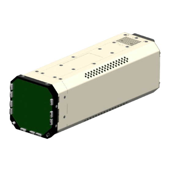
*Note: C151b is inclusive of TSO C92 and the ST3400 may be used to replace/upgrade C92 Ground Proximity Warning Systems 1.3.2 Physical Dimensions The ST3400 is enclosed in an ARINC 408, 3ATI form factor enclosure and is mounted to an instrument panel. -
Page 16: Interface Characteristics
Sandel pioneered smart interface technology makes the ST3400 compatible with all vintages of digital and analog aircraft systems. The ST3400 is software configurable and configuration data is stored internally and in an optional airframe-resident configuration module (active in software 2.10 and later). -
Page 17: Part Numbers
Part Numbers 1.5.1 ST3400 Part Number Part number ST3400-00x is the standard version of the ST3400. The –dash number indicates product variations -0xx Certified for Class A or B installations -1xx Certified for Class B installation only ”Minor variations” are reserved for future product enhancements or special applications. -
Page 18: Technical Standard Order Stipulation
A “Functional Ground Test Procedures/Report” and an “Operational Flight Check Procedures Report” are included in an Appendix to this manual. They should be used as a basis for validating the ST3400 equipment configuration and to verify proper installation and functional performance. A permanent copy of the STC form must be filed and maintained by the installing agency. -
Page 19: Installation Planning
2 INSTALLATION PLANNING The ST3400 has been designed to ensure maximum interoperability with all types avionics. Contact Sandel with any questions about interfacing to specific avionics equipment not covered in the installation drawings in this manual. General Information To simplify installation, after signals are wired to the ST3400 pins, on-screen setups are used in a post-installation procedure. -
Page 20: Additional Required Sensors, Allowed Configurations (Class-B)
GPS altitude or Corrected Barometric Altitude, or both. If both are supplied CBA is used as a backup to GPS altitude if available. See the installation diagrams for a list of approved receivers which can supply GPS altitude to the ST3400 For Class-A, at a minimum Barometric Vertical Speed and Barometric Altitude (either corrected or uncorrected) is required. -
Page 21: Airdata System Block Diagram
2.4.1 Airdata System Block Diagram Analog Coarse/ Fine Analog Vert Analog Analog Data Data Ternary Data Maintenance Page Selects Vert Spd Baro Alt Outputs to System 82002-IM-L ST3400 INSTALLATION MANUAL... -
Page 22: Oat Requirements
At extremely cold temperature these errors can be in excess of a thousand feet. The source of OAT can be internal (a probe connected to the ST3400) or from the airdata system. Most digital airdata systems provide, and the ST3400 can accept digital OAT. -
Page 23: Post Installation Procedures
400Hz (if used) only on the appropriate pins. 2. Review any special items particular to the subject aircraft installation. 3. Power up the ST3400 in maintenance mode and sequentially access each maintenance page to select the installed equipment. - Page 24 THIS PAGE INTENTIONALLY LEFT BLANK ST3400 INSTALLATION MANUAL 82002-IM-L...
-
Page 25: Interface Functions
All signals on J-2 (if used) that require excitation must use the same excitation as the inverter-2 input. If the installation of the ST3400 does not use any XYZ (ARINC407) signal sources, the inverter inputs are not required and should be grounded. -
Page 26: Flaps
Landing Gear Position input is required for Class A compliance and is recommended for Class B (if aircraft is retractable gear). The ST3400 has provisions on J-2 for Gear Down input discrete to indicate that the gear is in the “DOWN” position. -
Page 27: Audio Panel
If after adjustment the available speaker audio level is insufficient, turn up the master audio level at the ST3400 and make a corresponding reduction in the LL audio level at the headphone amplifier. -
Page 28: Heading System
The input of the ADF information is optional and not required for the Class A or Class B TAWS compliance. It is used in an application where the ST3400 is used to replace an existing RMI and ADF operation is desired or required. -
Page 29: Nav Receiver And Glideslope
OAT probe may be wired directly to the ST3400. The ST3400 has provisions for up to two simultaneous Air Data Computer ports depending on model. The primary receiver port on J-1 and the optional secondary receiver port on J-2. -
Page 30: Traffic
Reserved for Future use. In dual installations it is recommend to connect. 3.17 Uploading Equipment A USB interface is available on the front of the ST3400 to upload system software, terrain data, airport data, and configuration data into memory and to download configuration data from memory. -
Page 31: Installation
4 INSTALLATION The ST3400 should be installed in accordance with standards established by the customer’s installing agency, and existing conditions as to unit location and type of installation. Unpacking and Inspecting Equipment Exercise extreme care when unpacking the equipment. Make a visual inspection of the unit for evidence of damage incurred during shipment. -
Page 32: Electrical Installation Considerations
7. Power Wiring. To assure that the ST3400 will operate properly down to its rated minimum input voltage, ensure that two power wires of at least the recommended size are connected in accordance with the installation drawings. -
Page 33: Connector P1
ADF Discrete, Note: Not used when 429 is data source Note: For composite inputs see P2-42 A429 A side 429 Nav1A (RS422) + side 422 (RS232) Ground side Note: For composite inputs see P2-42 A429 B side 429 Nav1B (RS422) - side 422 (RS232) 82002-IM-L ST3400 INSTALLATION MANUAL... - Page 34 ADC Analog, Note: Not used when 429 is data source. (In) FMS1 A (A429) A side 429 Secondary (R422) + side 422 (R232) Ground side (A407) Synchro X (In) (A429) B side 429 FMS1 B (R422) - side 422 Secondary (R232) (A407) Synchro Y ST3400 INSTALLATION MANUAL 82002-IM-L...
-
Page 35: View Of Mating Connector To P1
Clone of audio from Audio1 which has the capability of Speaker Audio driving 8 ohm speaker directly. Volume separately trimmed with respect to LL audio, which acts as master. Audio Spkr 4.5.1 View of Mating Connector to P1 Outside View (Mating Connector) 82002-IM-L ST3400 INSTALLATION MANUAL... -
Page 36: Connector P2
ADF Discrete, Note: Not used when 429 is data source Note: For composite inputs see P2-42 A429 A side 429 Nav2A (RS422) + side 422 (RS232) Ground side Note: For composite inputs see P2-42 A429 B side 429 Nav2B (RS422) - side 422 (RS232) ST3400 INSTALLATION MANUAL 82002-IM-L... - Page 37 (BC) Discrete Discrete Valid Discrete Open/Gnd or Open/+28VDC. (In) (A429) A side 429 FMS2 A (R422) + side 422 Secondary (R232) Ground side (In) (A429) B side 429 FMS2 B (R422) - side 422 Secondary (R232) 82002-IM-L ST3400 INSTALLATION MANUAL...
-
Page 38: View Of Mating Connector To P2
For dual installations to feed cross-side system 429A Interlink A429 A side 429 For dual installations to feed cross-side system 429B Interlink A429 B side 429 4.6.1 View of Mating Connector to P2 Outside View (Mating Connector) ST3400 INSTALLATION MANUAL 82002-IM-L... -
Page 39: P3 Connector
TCAS to be at the proper ‘high’ (unasserted) voltage. If necessary, check with a voltmeter during installation. 4.7.1 View of Mating Connector to P3 Outside View (Mating Connector) 82002-IM-L ST3400 INSTALLATION MANUAL... -
Page 40: P4 Connector
Accepts ST3400 Configuration Module. Note: Configuration Module active in software 2.10 and above. Configuration module may be left connected to ST3400 using prior software versions but will not store data. The ST3400 may be operated with or without a configuration module connected. -
Page 41: Signal Type Electrical Characteristics
0Vdc +/- 5, 15Vdc Full Scale 90Vdc >500K VS_Sense 0Vdc +/- 5, 23.6Vdc Full Scale 90Vdc >500K VS Sig - 5 to +5Vdc = -10K to +10K FPM 30Vdc >500K TAS Sig 10Vdc Full Scale 90Vdc >500K 82002-IM-L ST3400 INSTALLATION MANUAL 4-11... - Page 42 0v/27.5 volt transition, any input network may be used that ensures that the discrete input pin is not within 1.0v from its nominal threshold shown in the table either in the active or inactive state. 4-12 ST3400 INSTALLATION MANUAL 82002-IM-L...
-
Page 43: Maintenance Mode
NOTE: WHEN DOING A FINAL TEST OF A SYSTEM MAKE SURE THE POWER HAS BEEN RECYCLED TO VERIFY CORRECT SETTINGS. To exit the maintenance mode for normal flight operations turn off the power for 15 seconds and restart the unit normally. 82002-IM-L ST3400 INSTALLATION MANUAL... - Page 44 THIS PAGE INTENTIONALLY LEFT BLANK ST3400 INSTALLATION MANUAL 82002-IM-L...
-
Page 45: Setup Procedures
The Windows based ST3400 TAWS Loader program is used to transfer terrain data, airport data, , and configuration data to the TAWS equipment memory. The Loader communicates with the ST3400 unit via the USB Port located in the lower right corner of the front bezel. -
Page 46: Configuration Module Status Page
Note “CM” will appear in the upper right corner to indicate that the configuration module is not operational. “ST3400 TO CM”: Selecting this option will allow stored ST3400 configuration data to be written to the configuration module and stored. NOTE:... -
Page 47: Maintenance Index Page
The Cursor points to the item, which may be modified or selected. If there are no selectable items on the currently displayed maintenance page, the Current Line Indicator is not displayed. The [UP] Soft key and [DOWN] Soft key are used to move the Cursor up and down through the list. 82002-IM-L ST3400 INSTALLATION MANUAL... -
Page 48: Soft Keys
Decrement If the maintenance item is a numeric value, this key will decreases the value; if a multiple-choice entry then will move to the previous choice. Hold to repeat. ST3400 INSTALLATION MANUAL 82002-IM-L... -
Page 49: Edit/Read Mode Indicator
6.2.5.2 Jump to a specific page Press the Soft key or the softkey to move the Cursor. [UP] [DOWN] Press the [SELECT] Soft key to jump to this page. 6.2.5.3 Step Through Pages Press the soft key. [PREV] [NEXT] 82002-IM-L ST3400 INSTALLATION MANUAL... -
Page 50: Maintenance
The modifiable values (Aircraft Type through FLTA Alert Type) show the overall configuration for the unit and allow the operator to change these items. Figure 6-2: System (Edit Mode) 6.3.1.1 Item An Item identifies each maintenance item. ST3400 INSTALLATION MANUAL 82002-IM-L... -
Page 51: Air Data Page
This will move the Cursor to the appropriate line and display the current input data value, input voltage (if applicable) and pin-pairs of the selected signal. CBA: Corrected Baro Altitude Input Baro Rate input (Vertical Speed) True Airspeed Figure 6-3: Air Data 82002-IM-L ST3400 INSTALLATION MANUAL... -
Page 52: Adf & Hdg Page
If a VALID signal is available, set appropriately to VALID HIGH or VALID LOW. The effect of these settings will be immediately shown at a VALID or INVALID data value at the top of the screen Figure 6-4: ADF & HDG ST3400 INSTALLATION MANUAL 82002-IM-L... -
Page 53: Discretes Maintenance Page
A Discrete may be VALID-LOW or VALID-HIGH. In either case a 30K resistor is connected to pull the signal to the invalid state (ground or aircraft power) as applicable unless the valid signal is applied. Figure 6-5: DISCRETES 82002-IM-L ST3400 INSTALLATION MANUAL... -
Page 54: Nav And Ils Page
GS data in addition to the analog GS flag. Back Course (from the HSI) discrete input may be VALID-LOW or VALID- HIGH. This is used to inhibit the Glideslope alert GPWS mode 5. Figure 6-6: NAV and ILS 6-10 ST3400 INSTALLATION MANUAL 82002-IM-L... -
Page 55: Radalt Maintenance Page
Radar Altimeter operation it is suggested that a test flight be performed in VFR conditions and the Radar Altitude be monitored on the ST3400 maintenance page simultaneously with the Radar Altimeter indicator to check for correct operation. -
Page 56: Gps/Fms
6.3.7.1 More Indicator The More Indicator (see Figure 6-8) indicates more choices than the listings currently displayed on the screen. An arrow pointing down indicates that more choices exist below the last listing currently being displayed. 6-12 ST3400 INSTALLATION MANUAL 82002-IM-L... -
Page 57: Tcas
[UP]/[DOWN] Soft keys to scroll through the various data items. Press the [MODEL] Soft key to exit the "Value" scroll function. If a ST3400 in the field is being upgraded to display Traffic, please contact the factory for a software key necessary to enable the traffic display. The Traffic key can be entered on this screen manually. -
Page 58: Status Page
6.3.9 Status Page The Status page (see Figure 6-9) shows a composite status of all the ST3400 inputs. Figure 6-9: STATUS 6-14 ST3400 INSTALLATION MANUAL 82002-IM-L... -
Page 59: Callouts
Use the [UP] or [DOWN] Softkeys to select a setup item, this will move the Cursor to the appropriate line. [+] and [-] select “ON” or “OFF for each callout. Radar Altimeter input is required for the Callouts to function. Figure 6-10: CALLOUTS 6-15 82002-IM-L ST3400 INSTALLATION MANUAL... -
Page 60: Post Installation
Soft key if with in the Maintenance pages or, press and hold the [OPER] Soft key if in the Flight Operation Display. Since these two soft keys are [MAINT] the same physical button, this quick access sequence is done by pressing the button twice. 7-16 ST3400 INSTALLATION MANUAL 82002-IM-L... -
Page 61: Post Installation Testing
The failure of the display itself is a major failure and will result in the inability to show further system-level error messages. 7.2.2 ST3400 TAWS/RMI Verify DC Power, AC Power and Ground inputs to the Sandel ST3400 TAWS/RMI J1, J2 and J3 connectors before installing Sandel TAWS/RMI ST3400. -
Page 62: Brightness/Audio Page
(P1-15) is used, adjust SPKR VOL to set the corresponding speaker volume. If the cockpit speaker is driven instead from the cockpit audio system, SPKR VOL is not used. During an alerts test, the external annunciators, if connected, will illuminate. Figure 7-1: Brightness/Audio 7-18 ST3400 INSTALLATION MANUAL 82002-IM-L... -
Page 63: Power Maintenance Page
Figure 7-2: Internal Diagnostics 1 Note: On ST3400 with Mod-A, the following differences should be noted: • The power supply monitor list is slightly different than shown above; • Any power supply out-of-tolerance will change from green to red. -
Page 64: Software Crc Page
CRC values of the data. Figure 7-3: Internal Diagnostics 2 7.2.11 ST3400 CONFIGURATION Configure and record configuration information from the ST3400 TAWS/RMI Maintenance and Summary pages Note: Meet all approved maintenance and safety conditions. Use of appropriate ground power for the aircraft is required. - Page 65 RECORD ST3400 TAWS/RMI CONFIGURATION PAGE EQUIPMENT FUNCTION DATA TYPE AIR DATA ADC-1 CBA1 AIR DATA ADC-2 CBA1 ADF & HEADING ADF-1 VALID ADF-2 VALID HDG-1 VALID HDG-2 VALID DISCERTES ALERT TEST FLAPS GEAR WHEELS WINDSHILD WIPERS 7-21 82002-IM-L ST3400 INSTALLATION MANUAL...
- Page 66 PAGE EQUIPMENT FUNCTION DATA TYPE NAV & ILS NAV-1 CALIBRATE NAV-2 CALIBRATE GS NO 1 GS NO 2 Back Course RADIO ALTIMETER RA-1 VALID Decision Height GPS/FMS-1 SELECTION GPS/FMS-2 SELECTION TRAFFIC SELECTION 7-22 ST3400 INSTALLATION MANUAL 82002-IM-L...
-
Page 67: Air Data Input Tests
7.2.12 AIR DATA INPUT TESTS Follow Aircraft Manufacturers instructions and connect Pitot/Static test box to the aircraft Pitot/Static system. Select ST3400 to Maintenance Page 3&4: AIR DATA monitor the #1 and #2 Air data inputs. Set the Pilot’s altimeter to field elevation. -
Page 68: Adf Input Tests
7.2.13 ADF INPUT TESTS Select ST3400 to Maintenance Page 5: ADF & HDG. SIGNAL FUNCTION RESULT PASS FAIL Tune #1 ADF to ADF1 Verify the #1 ADF bearing value station and select matches bearing to the station within ADF Mode. -
Page 69: Discrete Inputs Tests
7.2.15 DISCRETE INPUTS TESTS Check all discrete inputs that are interfaced to Sandel ST3400 TAWS/RMI. See Sandel ST3400 TAWS/RMI installation wiring diagrams for aircraft. Select ST3400 to Maintenance Page 6: DISCRETES. SIGNAL FUNCTION RESULT PASS FAIL Engage Autopilot AP ENGAGE Verify value “ENGAGED”... -
Page 70: Radar Altimeter
Altimeter Test set, the operator should consult Radar Altimeters manufactures test setup and procedures for operation of the test set. The test that will be performed to validate the ST3400 TAWS/RMI operation with the Radar Altimeter will be tests defined below. -
Page 71: Gps/Fms 1
Select ST3400 to Maintenance Page 8: RAD ALT SIGNAL FUNCTION RESULT PASS FAIL #1 Radar Altimeter #1 Radar Altimeter Value should Receiver/Transmitter. indicate within +-5 feet of Rad Alt Activate Rad Alt self test output. Test #1 Radar Altimeter RA1 FAIL... -
Page 72: Gps/Fms 2
7.2.22 Power up the GPS/FMS But do not initialize, do not accept/acknowledge Lat/Lon position, or enter and activate a flight plan. Verify the ST3400 flags the terrain display (GPS/FMS not active and GPS/FMS data output is not valid). Pass / Fail:... -
Page 73: Initialize Gps/Fms
7.2.23 Initialize GPS/FMS And, activate a valid flight plan. Verify that the ST3400 displays valid terrain, and is function properly. Place a metallic object over the GPS/FMS antenna so as to block reception of all GPS/FMS satellites. Verify the GPS/FMS position solution is no longer valid, and that the flight plan is no longer active. -
Page 74: Verify The St3400 Visibility And Accessibility
7.2.28 Verify the ST3400 visibility and accessibility Verify visibility and accessibility of the ST3400 display and controls from the pilot’s seat. View the display from normal, expected viewing angles. This should include viewing the display from all viewing angles that might be encountered during normal cockpit operations. - Page 75 THIS PAGE INTENTIONALLY LEFT BLANK 7-31 82002-IM-L ST3400 INSTALLATION MANUAL...
-
Page 77: Instructions For Continued Airworthiness
Information regarding new releases and the content details of the databases may be obtained by visiting the Sandel website. Database updates may be ordered on- line. It is up to the ST3400 customer to determine if a specific database is applicable to their operations. - Page 78 THIS PAGE INTENTIONALLY LEFT BLANK ST3400 INSTALLATION MANUAL 82002-IM-L...
-
Page 79: Installation Drawings
9 INSTALLATION DRAWINGS List of effective pages: Drawing Rev Title 82002-05 LAYOUT, ST3400 INSTALLATION 82002-07 LAYOUT, ST3400 82002-10 pp 1 SYSTEM BLOCK DIAGRAM 82002-10 pp 2 MINIMUM REQ BLOCK DIAGRAM 82002-10 pp 3 POWER & AUDIO 82002-10 pp 4 GPS/FMS ARINC 429... - Page 80 THIS PAGE INTENTIONALLY LEFT BLANK ST3400 INSTALLATION MANUAL 82002-IM-L...
-
Page 81: Appendix A: Equipment And Interfaces
429 LOW SPEED HONEYWELL GNS-Xls 429 HIGH SPEED II MORROW 2100 II MORROW 2101 TRIMBLE 2000/3000 RS422 TRIMBLE 2101 RS422 TRIMBLE 2101 I/O 429 LOW SPEED TRIMBLE 2101 I/O 429 HIGH SPEED UNIVERSAL UNS-1X 429 LOW SPEED 10-1 82002-IM-L ST3400 INSTALLATION MANUAL... -
Page 82: Arinc 429 Labels For Gps/Fms
10.2 RADAR ALTIMETER MANUFACTURER MODEL INTERFACE TYPE BENDIX/KING KRA405 ANALOG BENDIX/KING KRA405B ARINC 429 COLLINS ALT50 ANALOG COLLINS ALT50A ANALOG COLLINS ALT55 ANALOG COLLINS RAC870 ARINC 429 SPERRY RT-220 ANALOG SPERRY RT-300 ANALOG HONEYWELL APN-194 ANALOG 10-2 ST3400 INSTALLATION MANUAL 82002-IM-L... -
Page 83: Arinc 429 Labels For Radar Altimeter
INTERFACE TYPE BENDIX/KING KN-40 ARINC 429 BENDIX/KING KX165 ANALOG BENDIX/KING KNR634 ANALOG COLLINS VIR30/31/32 ANALOG COLLINS VIR432 ARINC 429 GARMIN GNS430/530 ARINC 429 10.5.1 ARINC 429 LABELS for NAV LABEL DATA LOCALIZER DEVIATION GLIDESLOPE DEVIATION LABEL 10-3 82002-IM-L ST3400 INSTALLATION MANUAL... -
Page 84: Airdata
Uncorrected Altitude Corrected Baro Altitude True Air Speed Total Air Temperature Baro Rate Static Air Temperature 10.7 TRAFFIC MODEL INTERFACE TYPE GoodricL- TCAS 791/A 3/GOODRICHh GoodrichL- Skywatch 3/GOODRICH HPSKYWATCH HP HONEYWELL CAS 66 RYAN 9900BX 10-4 ST3400 INSTALLATION MANUAL 82002-IM-L... -
Page 85: Appendix B: Environmental Qualification Form
TSO NUMBERS: C151a, C92c, C113 MANUFACTURER’S SPECIFICATION AND/OR OTHER APPLICABLE SPECIFICATION: a.) Design Requirements & Objectives For ST3400 TAWS, document number 82002-0010 b.) RTCA D0-160D Environmental Plan For Sandel ST3400 TAWS Class A/B, document number 82002-0090 MANUFACTURER: Sandel Avionics, Inc. ADDRESS:... - Page 86 THIS PAGE INTENTIONALLY LEFT BLANK 11-2 ST3400 INSTALLATION MANUAL 82002-IM-L...
-
Page 87: Appendix C: Stc
12 APPENDIX C: STC 12.1 STC Permission Please contact Sandel Avionics, Inc. for permission to use these STC’s. 12-1 82002-IM-L ST3400 INSTALLATION MANUAL... -
Page 88: Stc: Cessna 421C Series
12.2 STC: Cessna 421C Series 12-2 ST3400 INSTALLATION MANUAL 82002-IM-L... -
Page 89: Stc: King Air C90, 200, 300 And B300 Series
12.3 STC: King Air C90, 200, 300 and B300 Series 12-3 82002-IM-L ST3400 INSTALLATION MANUAL... - Page 90 Steps 390Hz 625Hz irem 8200 Plan Altitu tion Cras Susc Trans reco , Z: , Z: , Z: , Z: , Z: N & ents Susc eptib Susc Emiss ient 160Hz 150Hz 145Hz 150Hz 150Hz 12-4 ST3400 INSTALLATION MANUAL 82002-IM-L...
- Page 93 CAD GENERATED DRAWING, DIMENSIONS ARE IN INCHES DO NOT MANUALLY UPDATE TOLERANCES ARE: VISTA, CA APPROVALS DATE FRACTIONS DECIMALS ANGLES DRAWN P.TAYLOR 01/24/02 LAYOUT, ST3400 .XXX .005 CHECKED MATERIAL RESP ENG ST3400 3.285 FINISH MFG ENG NEXT ASSY USED ON DWG. NO.
- Page 94 TRAFFIC (OPTIONAL) SANDEL SANDEL SANDEL Vista, Ca. Vista, Ca. Vista, Ca. Category Category Category ST3400 INSTALLATION DRAWING ST3400 INSTALLATION DRAWING ST3400 INSTALLATION DRAWING Title Title Title SYSTEM BLOCK DIAGRAM SYSTEM BLOCK DIAGRAM SYSTEM BLOCK DIAGRAM Size Size Size Document Number...
- Page 95 SANDEL SANDEL ARINC 429 Vista, Ca. Vista, Ca. Vista, Ca. (OPTIONAL) Category Category Category 28VDC ST3400 INSTALLATION DRAWING ST3400 INSTALLATION DRAWING ST3400 INSTALLATION DRAWING Serial CONFIGURATION POWER & POWER GROUND Title Title Title MODULE MINIMUM REQ BLOCK DIAGRAM MINIMUM REQ BLOCK DIAGRAM...
- Page 96 Vista, Ca. Vista, Ca. Vista, Ca. THIS IS AN ACCEPTABLE ALTERNATIVE MEANS OF Category Category Category TAWS PWR ST3400 INSTALLATION DRAWING ST3400 INSTALLATION DRAWING ST3400 INSTALLATION DRAWING ENABLING TAWS AUDIO WHEN REQUIRED BY SYSTEM CONSIDERATIONS Title Title Title P3-8 (TCAS INH) POWER &...
- Page 97 SELECT SECONDARY INPUTS OPTIONAL SANDEL SANDEL SANDEL Vista, Ca. Vista, Ca. Vista, Ca. Category Category Category ST3400 INSTALLATION DRAWING ST3400 INSTALLATION DRAWING ST3400 INSTALLATION DRAWING Title Title Title GPS/FMS ARINC 429 GPS/FMS ARINC 429 GPS/FMS ARINC 429 Size Size Size...
- Page 98 SANDEL SANDEL SANDEL Vista, Ca. Vista, Ca. Vista, Ca. Horizontal Guidance only used. If GPS uses two RS232 ports, contact Sandel before Category Category Category ST3400 INSTALLATION DRAWING ST3400 INSTALLATION DRAWING ST3400 INSTALLATION DRAWING interfacing an RS232 OAT source. See OAT page.
- Page 99 NAV 429 B TX PRESSURE ALTITUDE INTERFACED TO RECEIVER #1 NAV 429 B IN #1 FMS RS232 IN HI RS232 TX 2. ST3400 MAINTENANCE PAGE ITEMS: Select 1 of the RS232 TX Outputs LNAV-1: GNS4XX/5XX (429_232) A Channel needs to be dedicated to...
- Page 100 Pwr or Ref PERFORM A FLIGHT TEST IN VFR CONDITIONS AND VIEW THE RA 200k Ohms +/- 200k Ohms +/- ALTITUDE READOUT ON THE ST3400 RA MAINTENANCE PAGE TO VERIFY THE ST3400 DATA MATCHES THE PILOT'S RADAR ALTITUDE 20% 1/4 watt SOFTWARE...
- Page 101 2. CONNECT DIGITAL SIGNALS AS REQUIRED. SANDEL SANDEL SANDEL Vista, Ca. Vista, Ca. Vista, Ca. Category Category Category ST3400 INSTALLATION DRAWING ST3400 INSTALLATION DRAWING ST3400 INSTALLATION DRAWING Title Title Title RADALT ARINC 429 RADALT ARINC 429 RADALT ARINC 429 Size...
- Page 102 #2 Heading not available when XYZ used for Flaps. See Airframe page. SANDEL SANDEL SANDEL Vista, Ca. Vista, Ca. Vista, Ca. Category Category Category ST3400 INSTALLATION DRAWING ST3400 INSTALLATION DRAWING ST3400 INSTALLATION DRAWING Title Title Title HDG ARINC 429 HDG ARINC 429 HDG ARINC 429 Size Size...
- Page 103 HEADING VALID HI or LOW AS REQ'D REQUIRES AC REFERENCE INPUT SANDEL SANDEL SANDEL Vista, Ca. Vista, Ca. Vista, Ca. #2 Optional Category Category Category ST3400 INSTALLATION DRAWING ST3400 INSTALLATION DRAWING ST3400 INSTALLATION DRAWING Title Title Title HDG XYZ HDG XYZ HDG XYZ Size Size Size...
- Page 104 1. OPTIONAL - USED FOR RMI OPERATION ONLY. SANDEL SANDEL SANDEL Vista, Ca. Vista, Ca. Vista, Ca. Category Category Category ST3400 INSTALLATION DRAWING ST3400 INSTALLATION DRAWING ST3400 INSTALLATION DRAWING Title Title Title ADF ARINC 429 ADF ARINC 429 ADF ARINC 429 Size...
- Page 105 1. OPTIONAL - USED FOR RMI OPERATION ONLY. SANDEL SANDEL SANDEL Vista, Ca. Vista, Ca. Vista, Ca. SECONDARY INPUTS OPTIONAL Category Category Category ST3400 INSTALLATION DRAWING ST3400 INSTALLATION DRAWING ST3400 INSTALLATION DRAWING Title Title Title ADF XYZ ADF XYZ ADF XYZ Size Size...
- Page 106 BOTTOM MOUNTED ANT 60A/B CONNECT PIN 32 SECONDARY INPUTS OPTIONAL SANDEL SANDEL SANDEL Vista, Ca. Vista, Ca. Vista, Ca. Category Category Category ST3400 INSTALLATION DRAWING ST3400 INSTALLATION DRAWING ST3400 INSTALLATION DRAWING Title Title Title ADF DC SIN/COS ADF DC SIN/COS ADF DC SIN/COS Size Size...
- Page 107 SELECT SANDEL SANDEL SANDEL Vista, Ca. Vista, Ca. Vista, Ca. Category Category Category ST3400 INSTALLATION DRAWING ST3400 INSTALLATION DRAWING ST3400 INSTALLATION DRAWING SECONDARY INPUTS OPTIONAL Title Title Title NAV & LOC ANALOG NAV & LOC ANALOG NAV & LOC ANALOG...
- Page 108 SANDEL SANDEL SANDEL Vista, Ca. Vista, Ca. Vista, Ca. Category Category Category ST3400 INSTALLATION DRAWING ST3400 INSTALLATION DRAWING ST3400 INSTALLATION DRAWING Title Title Title NAV & LOC ARINC 429 NAV & LOC ARINC 429 NAV & LOC ARINC 429 Size...
- Page 109 VALID "HIGH" 3. Pressure Altitude Tolerance: Altitude +/- 500'; for 1000' change in altitude tolerance +/-100' Title Title Title AIRDATA ANALOG AIRDATA ANALOG AIRDATA ANALOG 4. Requires ST3400 Mod A Size Size Size Document Number Document Number Document Number 82002-10 82002-10...
- Page 110 SANDEL SANDEL SANDEL Vista, Ca. Vista, Ca. Vista, Ca. SECONDARY INPUTS OPTIONAL Category Category Category ST3400 INSTALLATION DRAWING ST3400 INSTALLATION DRAWING ST3400 INSTALLATION DRAWING Title Title Title AIRDATA ARINC 429/419 AIRDATA ARINC 429/419 AIRDATA ARINC 429/419 Size Size Size...
- Page 111 429 OAT LABEL 1. See Section 3 for OAT probe requirements. SHIELD GROUND SOFTWARE ARINC 429 2. If GPS receiver uses two RS232 ports, contact SELECT Sandel before interfacing OAT using RS232 SANDEL SANDEL SANDEL Vista, Ca. Vista, Ca. Vista, Ca.
- Page 112 SELECT AP ENGAGE IN OUTPUT 28VDC SANDEL SANDEL SANDEL Vista, Ca. Vista, Ca. Vista, Ca. VALID HI Category Category Category ST3400 INSTALLATION DRAWING ST3400 INSTALLATION DRAWING ST3400 INSTALLATION DRAWING Title Title Title AIRFRAME AIRFRAME AIRFRAME Size Size Size Document Number...
- Page 113 3. OVERRIDE FLAP OVRD IN (MOM) TAWS TEST TAWS TEST IN (MOM) Diagram of each ST3400 Discrete Output NOTES: FLIGHT DATA RECORDER (for reference) 1. Annunicators and switches are optional. FUTURE ST3400 2. Annunicator power should be connected to Day/Light IMPLEMENTATION switch or photocell.
- Page 114 SHIELD GROUND FUTURE IMPLEMENTATION (Connection Recommended for Dual installs) SANDEL SANDEL SANDEL Vista, Ca. Vista, Ca. Vista, Ca. Category Category Category ST3400 INSTALLATION DRAWING ST3400 INSTALLATION DRAWING ST3400 INSTALLATION DRAWING Title Title Title INTERLINK INTERLINK INTERLINK Size Size Size Document Number...
- Page 115 Size Size Size Document Number Document Number Document Number 82002-10 82002-10 82002-10 3. ST3400 P3-8 Output is configured on Maintenance Page 2 (System). Create: Create: Create: Thursday, November 06, 2003 Thursday, November 06, 2003 Thursday, November 06, 2003 Mod: Mod:...
- Page 116 ST3400. GTN7XX series has 3) When using the RS232 for Altitude, select the RS232 GND additional channels 5 & 6 on P1005. Channel that is interfaced to the ST3400 and program Output as "EXTERNAL EGPWS" SIGNAL GND GPS/FMS 2...
Need help?
Do you have a question about the ST3400 and is the answer not in the manual?
Questions and answers