Table of Contents
Advertisement
Quick Links
Advertisement
Table of Contents

Related Manuals for Axminster Trade AT430DS


Summary of Contents for Axminster Trade AT430DS
- Page 1 Code 105584 Original Instructions AT430DS Drum Sander AT&M: 20/05/2019...
- Page 2 EN 60204-1: 2018 EN 60204-1: 2006 Type Drum Sander Model AT430DS and conforms to the machinery example for which the EC Type-Examination Certificate No YES-2019001-A1 has been issued by YEOU EIR SHUEN MACHINERY CO., LTD Signed at: No. 111-11, Yung He Rd., Da Ya Dist., 42877 Taichung City, Taiwan and complies with the relevant essential health and safety requirements.
- Page 3 PREFACE We appreciate your purchase of our machine. This machine is designed and manufactured for efficient, heavy-duty operations. This manual concerns the operation, safety and maintenance of the machine. This manual should be kept readily available to the operator for reference. The operator should read this manual ca refully before operation to ensure safe, smooth operation of the machine.
-
Page 4: Table Of Contents
TABLE OF CONTENTS 1. SAFETY INSTRUCTION ………………………………………………………... 1.1 SAFETY REGULATIONS …………………………………………………… 1.1.1 GENERAL SAFETY RULES ………………………………………..1.2 WARNING PLATES ………………………………………………………….. 2. SPECIFICATIOINS ………………………………………………………………. 2.1 SPECIFICATIONS ……………..…………………………………………..… 2.2 MACHINE NOISE ……………………………………………………………. 2.3 FUNCTION OF THE MACHINE ..………………………………………..… 2.4 MACHINE DIMENSIONS ..………………………...……………………..… 3. -
Page 5: Safety Regulations
1. SAFETY REGULATIONS 1.1 SAFETY REGULATIONS WARNING: FAILURE TO FOLLOW THESE RULES MAY RESULT IN SERIOUS PERSONAL INJURY. FOR YOUR OWN SAFETY, READ INSTRUCTION MANUAL BEFORE OPERATING THE TOOL. Learn the tool’s application and limitations as well as the specific hazards peculiar to it. KEEP GUARDS IN PLACE and in working order. - Page 6 recommended. Wear protective hair covering to contain long hair. ALWAYS USE SAFETY GLASSES. Also use face or dust mask if cutting operation is dusty. Everyday eyeglasses only have impact resistant lenses, they are NOT safety glasses. SECURE WORK. Use clamps or a vise to hold work when practical. It’s safer than using your hand and it frees both hands to operate tool.
-
Page 7: General Safety Rules
1.1.1. GENERAL SAFETY RULES Do not attempt to operate until you have read thoroughly and understand completely all instructions, rules, etc. contained in this manual. Failure to comply can result in accidents involving fire, electric shock, or serious personal injury. Keep owners manual and review frequently for continuous safe operation. - Page 8 hand and frees both hands to operate the machine. 12. DO NOT OVERREACH. Keep proper footing and balance at all times. 13. MAINTAIN MACHINE IN TOP CONDITION. Keep machine clean for best and safest performance. Follow instructions for lubricating and changing accessories. 14.
-
Page 9: Warning Plates
1.2 WARNING PLATES This machine has warning symbols attached on it as shown below to ensure proper and safe operation. These symbols are used on the machine to indicate points or instances of specific danger to operating personnel. Make sure to memorize these symbols and bring them to the attention of others as and when necessary. -
Page 10: Specificatioins
2. SPECIFICATIONS 2.1 SPECIFICATIONS AT430DS Main Motor 1.5HP,1PH Conveyor Motor DC 90W Max. Sanding Width 17” Max. Material Thickness 4” Min. Material Thickness 1/8” Minimum Stock Length 8” Conveyor Belt Speeds 0-22 FPM Sanding Drum Speed 1720 RPM(2258 FPM) Sanding Belt Size 3”... -
Page 11: Machine Noise
2.2. MACHINE NOISE DECLARED NOISE EMISSION VALUES in accordance with ISO 7960. Idling Operating Declared A-weighted Sound Power Level, Lward , in dB re 1 pW . Declared A-Weighted Emission Sound Pressure Level , lpAd , in dB re 20 μPa , at the operator’s position. -
Page 12: Function Of The Machine
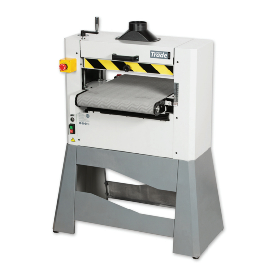
2.3. FUNCTION OF THE MACHINE Variable Speed Conveyor Steel Dust Scoop Maximizes Dust Collection Efficiency Two Adjustable Pressure Rollers Thickness Scale Welded Steel Construction Industrial-Duty Conveyor Belt Uses standard Tape Sandpaper Casting Iron Table 2.4 MACHINE DIMENSIONS 17”Drum sander... -
Page 13: Safety Rules For Machine Lifting
3. INSTALLAITON 3.1. SAFETY RULES FOR MACHINE LIFTING 1. Pay special attention to the balance of the machine while lifting. 2. Use a forklift with sufficient loading capacity to lift the machine. 3. Have another person help guide the way when lifting the machine. 4. -
Page 14: Transportation
enough space around the machine to open or remove doors/covers as required by the maintenance and service described in this manual. Electrical Installation Place this machine near an existing power source. Make sure all power cords are protected from traffic, material handling, moisture, chemicals, or other hazards. Make sure to leave assess to a means of disconnection the power source or engaging a lockout/tagout device. -
Page 15: Power Supply Requirement
3.4. POWER SUPPLY REQUIREMENT Insufficient voltage from factory power source may affect the power output of the motor and the function of the controller. It is important to connect this machine to the correct voltage in the factory power source. Use only an independent power source. 3.7 CONNECT POWER SOURCE WIRES 1. -
Page 16: Setup
3.6 SETUP Site Considerations Carefully unpack the Drum Sander from its crate and unsure that everything is in tact. When setting your machine in the desired location, make sure that you have enough machine clearance in order to use this machine to the full capacity. See the figure below for the minimum working clearance. - Page 17 Inventory The following is a description of the main components shipped with your machine. Lay the components out to inventory them. Note: If you can't find an item on this list, check the mounting location on the machine or examine the packaging materials carefully. Occasionally we pre-install certain components for shipping purposes.
- Page 18 be present on your stock as it comes out from the sander. This is normal. TEST RUN Connect your machine to the correct power source. Once it is connected you are ready to perform the first test run. Take a careful look in and around your machine before turning it on to ensure everything is in place, all screws and knobs are securely fastened and that all controls are working properly.
-
Page 19: Operation
4. OPERATION 4.1 BASIC CONTROLS A. Variable Speed Knob: Adjusts feed rate from 0–22 FPM. Rotate clockwise to increase feed speed, rotate counterclockwise to decrease feed speed. ON/OFF SWITCH: Turns motor ON/OFF. Hand Crank: Used to raise or lower the conveyor table to control depth of cut. Each full rotation of the hand crank raises or lowers the conveyor table approximately 1/16"... -
Page 20: Operation Instruction
4.2 OPERATION INSTRUCTION Operation Overview This overview gives you the basic process that happens during an operation with this machine. Familiarize yourself with this process to better understand the remaining parts of the Operation section. To complete a typical operation, the operator does the following: 1. - Page 21 sanding passes to prevent gouges. When the drum moves from sanding a wide surface to sanding a narrow surface, the load on the motor will be reduced, and the drum will speed up, causing a gouge. • DO NOT edge sand boards. This can cause boards to kickback, causing serious personal injury.
- Page 22 conveyor belt may rub against the chain, leaving grease on the belt. 2. Turn the sander ON, start the conveyor, and feed the workpiece into the sander. SLOWLY raise the conveyor table until the workpiece makes light contact with the sanding drum. This is the correct height to begin sanding the workpiece.
- Page 23 Paper Replacement 1. Disconnect the sander from the powersource! 2. Open the top cover to expose the drum. 3. Unwind the old sandpaper and notice the direction that it was wrapped around the drum. 4. Use the old sandpaper as a pattern to cutout the new sandpaper, or use the pattern in Figure 1, to cut the sandpaper to the necessary shape.
-
Page 24: Adjustment
4.3 ADJUSTMENT TENSION AND TRACKING After reasonable usage of the drum sander, the conveyor may slightly stretch and will require to be tensioned. When tensioning the conveyor belt, it is important to do so from both sides and not to tension one side more than the other as this may lead to more tracking problems. - Page 25 TRACKING The conveyor must track straight for proper sanding. If the conveyor tracks to either side and not straight, you must fix the tracking. When tracking your conveyor, remember that this process can take some time and that proper balance and patience is required.
- Page 26 MAINTENANCE Cleaning and maintaining this machine is relatively easy. It is imperative to vacuum or use an air blower to clean off wood dust from internal components from time to time to keep the machine clean. To clean your sandpaper from time to time to preserve the life, you can use a rubber abrasive cleaner and run it on the drum as it spins.
- Page 27 THICKNESS SCALE CALIBRATION After some time you may notice that the thickness scale can be a little off. In order to sand accurately you must make sure that the thickness scale is calibrated properly and this is an easy process to do every once in a while. 1) Sand a scrap work piece with the sander and measure the thickness of the finished piece.
- Page 28 Adjust the level of conveyor belt and sanding drum The standard is distance A=B When the sanding drum titles left or right, please lose the 2 nuts (C) to adjust. Adjust steps: Right side is fixing end, please adjust left 2 bolts for level. 1.
- Page 29 3. Raising the table till the sanding drum touch the 2 level plates equally without any space in between. (see fig.2) then take out the 2 level plate and tight the 2 nuts again. (fig.2)
-
Page 30: Mainteance
5. MAINTEANCE 5.1 MAINTENANCE & TROUBLE SHOOTING SYMPTOM POSSIBLE CAUSE POSSIBLE SOLUTION Machine is vibrating 1. V Belts are worn or 1. Inspect the belts and too much or is too loose replace with same noisy 2. Motor or other integral size or re-tension component is loose 2. - Page 31 SYMPTOM POSSIBLE CAUSE POSSIBLE SOLUTION Machine doesn’t turn 1. Capacitor is faulty 1. Test and replace on or trips breaker 2. Centrifugal switch is capacitor if needed when turned on faulty 2. Adjust or replace 3. Motor ON/OFF switch is centrifugal switch faulty 3.
- Page 32 SYMPTOM PROSSIBLE CAUSE POSSIBLE SOLUTION Sandpaper tears off 1. Sand paper is not 1. Re-check to ensure drum or wears securely fastened to paper is fastened to excessively drum drum using spring 2. Nail or metal piece in loaded release wood being sanded 2.
-
Page 33: Electric
6. ELECTRIC 6.1 SAFETY RULES FOR ELECTRICAL CONTROL SYSTEM Only personnel who are properly trained and have adequate knowledge and skill should undertake all electrical/electronic troubleshooting and repair. Do not alter or bypass protective interlocks. Before starting, read and observe all warning labels. When trouble shooting make sure the power source has been disconnected and main switch has been locked. -
Page 34: Parts List & Diagrams
7. . Parts List & Diagrams... - Page 37 REF. DESCRIPTION 101 CORD 102 CORD HOLDER 103 FLAT HEAD CAP SCREW 104 NYLON NUT 5/16" 105 FLAT HEAD CAP SCREW M6 106 FLAT HEAD CAP SCREW M4 107A 4" DUST PORT 108 REAR PANEL 109 HINGE 110A TOP COVER 111 KNOB 5/16 114 FLAT WASHER 115A BRACE...
- Page 38 REF. DESCRIPTION 202 HANDLE 203 HANDLE BASE 204A CU WHSHER 205 SCREW HEIGHT ADJUSTMENT(LONG) 206 EXTERNAL RETAINING RING S25 207 FLAT WASHER 208 ROLLER BRACKET 210 FLAT HEAD CAP SCREW M8 211 NUT M10 212 SCREW M10 213 FLAT WASHER 1/4 217 SPROCKET M10 218 SET SCREW M5 220 FLAT HEAD CAP SCREW M5...
- Page 39 REF. DESCRIPTION 301 KEY 6 302 SET SCREW 1/4 303 SPINDLE PULLEY 304 CARRIAGE BOLT 305 BEARING ASSY INBOARD 306 SET SCREW M6 310 FLAT HEAD CAP SCREW M3 311 DRUM 312 BELT FASTER ASSY 313 SOCKET HEAD CAP SCREW M4 314 SPRING 315 BRACKET RIGHT ROLLER 316 BRACKET ROLLER SUPPORT...
- Page 40 Optional Accessories REF. DESCRIPTION S01 STAND BRACKET PLANE S02 CARRIAGE BOLT S03 RUBBER FEET S04 HEX BOLT 5/16" S06 HEX NUT 5/16" S07 FLAT WASHER 5/16" S08 STAND SIDE BRACKET S09 HEX BOLT 5/16"...
- Page 42 The Axminster guarantee is available on Craft, Trade, Engineer, Air Tools & CNC Technology Series machines Buy with confidence from Axminster! So sure are we of the quality, we cover all parts and labour free of charge for three years! For more information visit axminster.co.uk/3years The packaging is suitable for recycling.
Need help?
Do you have a question about the AT430DS and is the answer not in the manual?
Questions and answers