Beckhoff BK9105 Documentation

Beckhoff BK9105 Documentation

Bus coupler for ethernet/ip
Table of Contents

Advertisement

Documentation
BK9055 and BK9105
Bus Coupler for Ethernet/IP
Version:
Date:
2.0.0
2019-04-12

Advertisement

Table of Contents
loading

Summary of Contents for Beckhoff BK9105

  • Page 1 Documentation BK9055 and BK9105 Bus Coupler for Ethernet/IP Version: 2.0.0 Date: 2019-04-12...
  • Page 3: Table Of Contents

    Documentation issue status ...................... 7 2 Product overview............................ 8 
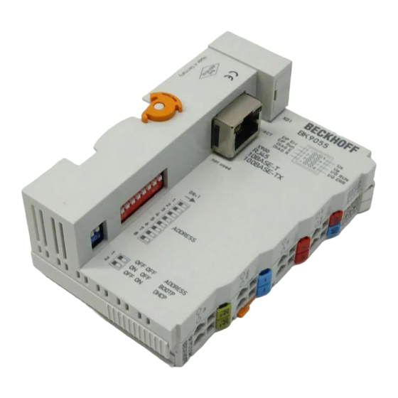
BK9055 - Introduction ........................ 8 BK9105 - Introduction ........................ 9 Technical data .......................... 10 The Beckhoff Bus Terminal system .................... 10 Ethernet ............................ 12 3 Mounting and wiring.......................... 14 Dimensions ............................ 14 Installation on mounting rails ...................... 15 Power supply, potential groups ....................... 16 ATEX - Special conditions (standard temperature range) ............... 18...
  • Page 4 Table of contents Support and Service ........................ 68 Version: 2.0.0 BK9055 and BK9105...
  • Page 5: Foreword

    The TwinCAT Technology is covered, including but not limited to the following patent applications and patents: EP0851348, US6167425 with corresponding applications or registrations in various other countries. ® EtherCAT is registered trademark and patented technology, licensed by Beckhoff Automation GmbH, Germany. Copyright © Beckhoff Automation GmbH & Co. KG, Germany.
  • Page 6: Safety Instructions

    All the components are supplied in particular hardware and software configurations appropriate for the application. Modifications to hardware or software configurations other than those described in the documentation are not permitted, and nullify the liability of Beckhoff Automation GmbH & Co. KG. Personnel qualification This description is only intended for trained specialists in control, automation and drive engineering who are familiar with the applicable national standards.
  • Page 7: Documentation Issue Status

    3200B2020000 The firmware in this example is B2. In order to update your firmware, you require the KS2000 configuration software and the serial cable included with that software. You will find the firmware under www.beckhoff.com. Firmware Description DIP-Switch Settings [} 21] New: K-Bus Counter [} 31]...
  • Page 8: Product Overview

    Therefore, new adjustments are not necessary in the event of replacement of a Bus Terminal. The controller carries out the desired setting automatically after switching on. Version: 2.0.0 BK9055 and BK9105...
  • Page 9: Bk9105 - Introduction

    The I/O stations can thus be configured with a line topology, instead of the classic star topology. In many applications this significantly reduces the wiring effort and the cabling costs. The maximum distance between two couplers is 100 m. Up to 20 BK9105 Bus Couplers are cascadable, so that a maximum line length of 2 km can be achieved.
  • Page 10: Technical Data

    BK9055: star wiring BK9105: line or star wiring Cascading up to 20 BK9105 or max. line length 2 km The Beckhoff Bus Terminal system Up to 256 Bus Terminals, with 1 to 16 I/O channels per signal form The Bus Terminal system is the universal interface between a fieldbus system and the sensor / actuator level.
  • Page 11 Bus Couplers for all usual bus systems The Beckhoff Bus Terminal system unites the advantages of a bus system with the possibilities of the compact series terminal. Bus Terminals can be driven within all the usual bus systems, thus reducing the controller parts count.
  • Page 12: Ethernet

    IP, TCP, UDP, ARP and ICMP. Transmission Control Protocol (TCP) The Transmission Control Protocol (TCP) which runs on top of IP is a connection-oriented transport protocol. It includes error detection and handling mechanisms. Lost telegrams are repeated. Version: 2.0.0 BK9055 and BK9105...
  • Page 13 It is used by end devices, to exchange information about the current status of the internet protocol. Address Resolution Protocol (ARP) Performs conversion between the IP addresses and MAC addresses. BootP The BootP protocol allows the TCP/IP address to be set or altered, by addressing the network device with its MAC-ID. BK9055 and BK9105 Version: 2.0.0...
  • Page 14: Mounting And Wiring

    Mounting and wiring Dimensions The system of the Beckhoff Bus Terminals is characterized by low physical volume and high modularity. When planning a project it must be assumed that at least one Bus Coupler and a number of Bus Terminals will be used.
  • Page 15: Installation On Mounting Rails

    Terminal electronics. • The power contacts deal with the supply for the field electronics and thus represent a supply rail within the Bus Terminal block. The power contacts are supplied via terminals on the Bus Coupler. BK9055 and BK9105 Version: 2.0.0...
  • Page 16: Power Supply, Potential Groups

    The current drawn from the power contacts must not exceed 10 A for long periods. The current carrying capacity between two spring-loaded terminals is identical to that of the connecting wires. Version: 2.0.0 BK9055 and BK9105...
  • Page 17: Fig. 4 Electrical Isolation

    Bus/E-Bus electronics in the Bus Coupler and the K-Bus/E-Bus itself in an electrically isolated manner. The supply voltage is also used to generate the operating voltage for the fieldbus. Note: All Bus Terminals are electrically isolated from the K-Bus/E-bus. The K-Bus/E-bus is therefore completely electrically isolated. Fig. 4: Electrical isolation BK9055 and BK9105 Version: 2.0.0...
  • Page 18: Atex - Special Conditions (Standard Temperature Range)

    80°C at the wire branching points, then cables must be selected whose tempera- ture data correspond to the actual measured temperature values! • Observe the permissible ambient temperature range of 0 to 55°C for the use of Beckhoff fieldbus compo- nents standard temperature range in potentially explosive areas! •...
  • Page 19: Atex - Special Conditions (Extended Temperature Range)

    80°C at the wire branching points, then cables must be selected whose tempera- ture data correspond to the actual measured temperature values! • Observe the permissible ambient temperature range of -25 to 60°C for the use of Beckhoff fieldbus com- ponents with extended temperature range (ET) in potentially explosive areas! •...
  • Page 20: Atex Documentation

    Notes about operation of the Beckhoff terminal systems in potentially explosive ar- eas (ATEX) Pay also attention to the continuative documentation Notes about operation of the Beckhoff terminal systems in potentially explosive areas (ATEX) that is available in the download area of the Beckhoff homepage http:\\www.beckhoff.com! Version: 2.0.0...
  • Page 21: Parametrization And Commissioning

    • Set all the DIP switches to OFF, and switch the Bus Coupler on again. • The I/O RUN and I/O Error LEDs light steadily. • Make the desired setting in accordance with the following table. BK9055 and BK9105 Version: 2.0.0...
  • Page 22: Network Classes

    172.16.xxx.xxx (xxx stands for a number between 0 and 255. 0 is usually used by the router/ switch and should therefore remain reserved). In order to see the PC's own address, the command ipconfig can be entered into a DOS window under Windows NT/2000/XP. Version: 2.0.0 BK9055 and BK9105...
  • Page 23: Ip Address

    Fig. 7: DIP switch Switch no. Valence In this example ON OFF ON Value Total=201 Software reset A software reset is required to save changes in the Bus Coupler tables. A hardware reset (power on/off) is not sufficient! BK9055 and BK9105 Version: 2.0.0...
  • Page 24: Address Configuration Via Arp

    123 bytes is permitted for reconfiguration of the IP address (<ping -l "IP address>) necessary. Example 1. C:>ping 172.16.17.255 2. C:>arp -a 172.16.17.255       00-01-05-00-11-22 3. C:>arp -d 172.16.17.255 4. C:>arp -s 172.16.44.44 00-01-05-00-11-22 5. C:>ping -l 123 172.16.44.44 Version: 2.0.0 BK9055 and BK9105...
  • Page 25: Address Configuration Via Bootp Server

    Fig. 8: Beckhoff BootP Server - DIP switch settings for statically stored IP address When choosing this mode, power cycling the BK9105 with the dip switches set to ON 1-9 will keep the IP address set by the BootP server. The BootP server does not need to be present after this point.
  • Page 26: Fig. 10 Beckhoff Bootp Server Configuration - Start

    Parametrization and commissioning Fig. 10: Beckhoff BootP server configuration - Start Then, start the server and reboot the BK9105. After a connection and an IP address are established, the following time stamp appears: Version: 2.0.0 BK9055 and BK9105...
  • Page 27: Fig. 11 Beckhoff Bootp Server Configuration - Time Stamp

    It is not possible to change dip switches 1 to 9 for a static IP address. They must remain on. If using the BootP server to assign the address every time the BK9105 is powered on, make sure dip switch 9 is on.
  • Page 28: Fig. 12 Rockwell Bootp/Dhcp Server 2.3 - Mac Address

    Parametrization and commissioning Take note that the dip switches 1 to 8 no longer hold any addressing capabilities. The MAC Address begins with 00-01-05-xx-xx-xx (see under the BK9105 to find the MAC address). Fig. 12: Rockwell BOOTP/DHCP Server 2.3 - MAC address After a successful addressing you can disable the BOOTP addressing.
  • Page 29: Setting The Address Using A Dhcp Server

    The subnet mask is a 32-bit number: • Ones in the mask indicate the subnet part of an address space. • Zeros indicate that part of the address space which is available for the host IDs. BK9055 and BK9105 Version: 2.0.0...
  • Page 30: Testing The Ip Address

    1 to 8 are set to ON). The IP address of the IP67 Fieldbus Boxes are set to 172.16.18.(rotary switch setting). • Start the DOS Window • Send a Ping to IP address 172.16.17.xxx • Read the MAC-ID with arp -a. Version: 2.0.0 BK9055 and BK9105...
  • Page 31: Configuration

    Status DWord 0 Control DWord 0 1...x complex terminals* complex terminals* x...y digital terminals** digital terminals** *) complex terminals, example KL15xx, KL25xx, KL3xxx, Kl4xxx, KL5xxx, KL6xxx, KL8xxx **) digital terminals, example KL1xxx, KL2xxx, KM1xxx, KM2xxx BK9055 and BK9105 Version: 2.0.0...
  • Page 32 16 to 23 24 to 31 K1 - 0->1 rising Trig K-Bus Reset R1 - 1->0 falling Trig Reboot BK9105 L1 - 1-> Outputs are frozen L2 - 1-> Leave K-Bus Cycle, if L1 and L2 TRUE then is only L2 active *) Firmware version B3 necessary Version: 2.0.0...
  • Page 33: Ethernetip Tag Wizard

    Key Concepts With this tool a user will be able to create the Beckhoff IO Rack, save the IO mapping configuration and Import that configuration into RSLogix 5000. RSLogix 5000 does not need to be installed on the PC you have the Tag Wizard on, however it will be convenient.
  • Page 34: Fig. 15 Ethernetip Tag Wizard

    Fig. 15: EthernetIP Tag Wizard All one has to do is simply save this configuration as an .L5K file to the desired location. In this example, all files are saved to the root directory of the Tag Wizard. Version: 2.0.0 BK9055 and BK9105...
  • Page 35: Fig. 16 Ethernetip Tag Wizard - Save As Type

    It is VERY important that the scanner is added just as it appers in your .L5K file. Fig. 17: EthernetIP Tag Wizard - EthernetIPMaster.txt At this point all one has to do is double click on EtherNetIPConfigTool.exe and it will open. Once open, add your BK9105 or IL230x-B905 to the configuration. BK9055 and BK9105 Version: 2.0.0...
  • Page 36: Fig. 18 Ethernetip Tag Wizard - Ethernetipconfigtool

    The software automatically is adding the 230x combo box to your configuration. At this point you simply add the IO to your configuration in the order that they are left to right on the coupler, by simply double clicking on the correct terminal. Version: 2.0.0 BK9055 and BK9105...
  • Page 37: Fig. 21 Ethernetip Tag Wizard - Adding The Io To Cour Configuration

    To review, all one has to do is simply select the coupler you want to review and then Report>Coupler (Or network [If network is selected only the first coupler will show graphically but the mapping below is correct]) Fig. 22: EthernetIP Tag Wizard - selections BK9055 and BK9105 Version: 2.0.0...
  • Page 38: Fig. 23 Ethernetip Tag Wizard - Mapping

    Fig. 24: EthernetIP Tag Wizard - Save To L5K file When saving to a L5K file you are prompted to select the correct Ethernet IP master (This list is read from the text file mentioned earlier). Version: 2.0.0 BK9055 and BK9105...
  • Page 39: Fig. 25 Ethernetip Tag Wizard - Choose The Correct Ethernet Ip Master

    Next you will be prompted to select the correct path to the stored .L5K file, and select Open. Once opened you will notice an AB.L5K file in the same directory you saved the original L5K file. Fig. 27: EthernetIP Tag Wizard - select the correct path to the stored .L5K file BK9055 and BK9105 Version: 2.0.0...
  • Page 40: Fig. 28 Ethernetip Tag Wizard - Abl5K.l5K

    Parametrization and commissioning Fig. 28: EthernetIP Tag Wizard - ABL5k.L5K Go back to RSLogix 5000, File>Open> Fig. 29: EthernetIP Tag Wizard - open the L5K file Select the NEW .L5K file then Import Version: 2.0.0 BK9055 and BK9105...
  • Page 41: Fig. 30 Ethernetip Tag Wizard - Safe The Imported Project

    Parametrization and commissioning Fig. 30: EthernetIP Tag Wizard - Safe the Imported Project Now to check out all of the new IO BK9055 and BK9105 Version: 2.0.0...
  • Page 42: Fig. 31 Ethernetip Tag Wizard - Check Out All Of The New Io

    Fig. 31: EthernetIP Tag Wizard - check out all of the new IO Please note to look in the Controller tags for not only did the software create new module defined tags, it labeled them accordingly in the Logical order, NOT the physical order. Version: 2.0.0 BK9055 and BK9105...
  • Page 43: Fig. 32 Ethernetip Tag Wizard - Controller Tags

    After the import is successful, please see that the Coupler Status and Coupler Control is described at the bit level. Also the status and control for each complex channel is defined with the HBYTE- >Empty LBYTE Status or Ctrl as the upper byte is padded. BK9055 and BK9105 Version: 2.0.0...
  • Page 44: Export To Rockwell

    Create a master Ethernet IP (limitation only master, not Multimaster support) Fig. 33: Export to Rockwell - Create a master Ethernet IP Save as the project as .L5k format Fig. 34: Export to Rockwell - Save as the project as .L5k format, step 1 Version: 2.0.0 BK9055 and BK9105...
  • Page 45: Fig. 35 Export To Rockwell - Save As The Project As .L5K Format, Step 2

    Fig. 35: Export to Rockwell - Save as the project as .L5k format, step 2 Create the project with the configurator and export with the push button AB CSV Fig. 36: Export to Rockwell - export with the push button AB CSV Select the file L5k, which you have generated BK9055 and BK9105 Version: 2.0.0...
  • Page 46: Fig. 37 Export To Rockwell - Select The Created File L5K

    Parametrization and commissioning Fig. 37: Export to Rockwell - Select the created file L5k Open AB's tool, and select open Fig. 38: Export to Rockwell - open the ABL5K.L5K Select the file ABL5K.L5K (fixed name!) Version: 2.0.0 BK9055 and BK9105...
  • Page 47: Fig. 39 Export To Rockwell - Select The File Abl5K.l5K

    Parametrization and commissioning Fig. 39: Export to Rockwell - Select the file ABL5K.L5K Save the project as ACD Fig. 40: Export to Rockwell - Save the project as ACD Read the import configuration, with the comments BK9055 and BK9105 Version: 2.0.0...
  • Page 48: Fig. 41 Export To Rockwell - Read The Import Configuration

    Parametrization and commissioning Fig. 41: Export to Rockwell - Read the import configuration Version: 2.0.0 BK9055 and BK9105...
  • Page 49: Fig. 42 Export To Rockwell - Read The Import Configuration With Comments

    Parametrization and commissioning Fig. 42: Export to Rockwell - Read the import configuration with comments BK9055 and BK9105 Version: 2.0.0...
  • Page 50: Error Handling And Diagnosis

    On the upper right hand side of the Bus Couplers are two more green LEDs that indicate the supply voltage. The left hand LED indicates the presence of the 24 V supply for the Bus Coupler. The right hand LED indicates the presence of the supply to the power contacts. Fig. 43: BK9105 Diagnostic LEDs Version: 2.0.0 BK9055 and BK9105...
  • Page 51: Fig. 44 Bk9055, Bk9105 - Leds

    Error handling and diagnosis Fig. 44: BK9055, BK9105 - LEDs LEDs for power supply diagnosis Meaning LED Us The power supply voltage Us is not present The power supply voltage Us is present LED Up The power supply voltage Up (for Power Contacts) is not present...
  • Page 52 • Red LED is ON, green LED show you the Error Code flashing 2 times (1 Sec) • Red LED OFF, green LED off • Red LED flashing 5 times (1 Sec), error argument, green LED off Fig. 45: Example for Error Code and Error Argument Version: 2.0.0 BK9055 and BK9105...
  • Page 53 KS2000 configuration software 16 pulses Length of the K-Bus data is no Start the Bus Coupler again. If the error occurs longer correct again, restore the manufacturers setting using the KS2000 configuration software BK9055 and BK9105 Version: 2.0.0...
  • Page 54: Appendix

    Appendix First Steps Mapping The BK9105 can be mapped as short integer (byte), integer (word), or double integer (double word). In the following description it is mapped as double integer! Addressing with the BOOTP/DHCP Server 2.3 Switch the DIP Switch 1 to 8 OFF and DIP 9 to 10 ON.
  • Page 55 When creating a new project make sure to select the correct controller type and controller settings. In this example we are using a SoftLogix Virtual Chasis, with the BK9105 (Beckhoff EthernetIP Bus coupler) Fig. 48: First Steps - Create a new PLC project BK9055 and BK9105 Version: 2.0.0...
  • Page 56 Fig. 49: First Steps - Add Ethernet IP Module Add Ethernet IP Box When adding the BK9105 box you must select the "ETHERNET-MODULE" as it is a generic Ethernet/IP device and we will configure it to work with our BK9105. Fig. 50: First Steps - Add Ethernet IP Box Configuring the BK9105 in RSLogix For the example here we used two KL1012 terminals and two KL2032.
  • Page 57 DINT is the Status for both the input and output data. At this point if you have the controller in RUN mode you will be able to toggle inputs and see the value in "bk9105:I.Data[1]" change and you should be able to update the values in "bk9105:O.Data[1]"...
  • Page 58: First Steps - Example

    The process image table (I/O map) is displayed in double word format below the figure. In order to properly configure the Ethernet Bridge, the process image of the Beckhoff BK9105 node must be determined. When the coupler is powered up, it automatically addresses the I/O modules of the node. The data for complex modules (modules using 2 or more bytes) are mapped first in the process image in the order of their physical position after the coupler.
  • Page 59 • Double Word 8: KL1104 bit 16-19, KL14008 bit 20-27 the remainder bits are not used (High Word) and Data In (1) KL1501(Low Word) Output Process Image • Double Word 0: BK9105 Control • Double Word 1: Channel 1 KL3064 (High Word) and Status (Low Word) • Double Word 2: Channel 2 KL3064 (High Word) and Status (Low Word) •...
  • Page 60 This is what the Controller Tags should look like. The graphic below illustrates exactly where one would look to find the Data In (1) KL1501 as well as the third digital output, KL2134 channel 3. Fig. 55: KL1501's Data In Version: 2.0.0 BK9055 and BK9105...
  • Page 61 Open RSLogix 5000 and create a new PLC project When creating a new project make sure to select the correct controller type and controller settings. This example uses a SoftLogix Virtual Chasis, with the BK9105 (Beckhoff EthernetIP Bus coupler). BK9055 and BK9105...
  • Page 62 Fig. 58: Example - Add an Ethernet IP Module Add an Ethernet IP Box When adding the BK9105 box, select the "ETHERNET-MODULE", since it is a generic Ethernet/IP device, and it will be configured to work with the BK9105. Version: 2.0.0...
  • Page 63 ◦ There will always be 4 bytes of input and 4 bytes of output data used. ◦ Digital IO: Each channel will consume 1 bit of process data. ◦ Complex IO: Please refer to terminal documentation for consumed data size. Fig. 60: Example - Configure the BK9105 in RSLogix BK9055 and BK9105 Version: 2.0.0...
  • Page 64: General Operating Conditions

    Status for both the input and output data. At this point, if the controller is in RUN mode, toggle inputs to see the value in "bk9105:I.Data[1]" change. One should be able to update the values in "bk9105:O.Data[1]" and see the outputs change.
  • Page 65 This case therefore is a BK2000 - produced in the 9th calendar week - in the year 2001 - containing the BF firmware version - and using the 6th hardware version - with no special indications BK9055 and BK9105 Version: 2.0.0...
  • Page 66: Test Standards For Device Testing

    Kevin Washburn and Jim Evans Publisher: ADDISON-WESLEY Longmann Verlag Modbus/TCP http://www.modicon.com/ http://www.modbus.org TwinCAT Beckhoff Information System http://infosys.beckhoff.com List of Abbreviations Automation Device Specification. IP (20) Bus Terminal protection class Industrial PC Inputs and outputs Version: 2.0.0 BK9055 and BK9105...
  • Page 67: Support And Service Usa

    TwinCAT The Windows Control and Automation Technology Support and Service USA Beckhoff USA offers comprehensive support and service, making available fast and competent assistance with all questions related to Beckhoff products and system solutions. • support • design, programming and commissioning of complex automation systems •...
  • Page 68 Beckhoff's branch offices and representatives Please contact your Beckhoff branch office or representative for local support and service on Beckhoff products! The addresses of Beckhoff's branch offices and representatives round the world can be found on her internet pages: http://www.beckhoff.com You will also find further documentation for Beckhoff components there.
  • Page 69 Network classes........................... Fig. 7 DIP switch............................ Fig. 8 Beckhoff BootP Server - DIP switch settings for statically stored IP address......Fig. 9 Beckhoff BootP Server - DIP switch settings for dynamically set IP address......Fig. 10 Beckhoff BootP server configuration - Start.................
  • Page 70 First Steps - Add Ethernet IP Module ..................Fig. 50 First Steps - Add Ethernet IP Box....................Fig. 51 First Steps - Configure the BK9105 in RSLogix................Fig. 52 First Steps - Work with IO data....................Fig. 53 Example of a Bus Terminal Block....................

This manual is also suitable for:

Bk9055

Table of Contents