Table of Contents
Advertisement
Available languages
Available languages
1.753.000.085
IM-G10-02
BR Rev.00
25P e 25PSS
Manual de Instalação e Manutenção
1. Termo de Garantia
2. Informações relativas
à devolução
3. Informações Gerais de
Segurança
4. Informações do produto
5. Instalação
6. Comissionamento
7. Correção de Defeitos
8. Manutenção
9. Peças de Reposição
10. Informações Comple-
mentares
1
IM-G10-02
Advertisement
Table of Contents

Related Manuals for Spirax Sarco 25P


Summary of Contents for Spirax Sarco 25P
- Page 1 1.753.000.085 IM-G10-02 BR Rev.00 25P e 25PSS Manual de Instalação e Manutenção 1. Termo de Garantia 2. Informações relativas à devolução 3. Informações Gerais de Segurança 4. Informações do produto 5. Instalação 6. Comissionamento 7. Correção de Defeitos 8. Manutenção 9.
-
Page 2: Termo De Garantia
A única obrigação da Spirax Sarco com o Termo de Garantia é de reparar ou substituir qualquer produto que considerarmos defeituoso. A Spirax Sarco reserva os direitos de inspecionar o produto na instalação do cliente fim ou... -
Page 3: Informações Gerais De Segurança
3. Informações Gerais de Segurança A operação segura dos produtos descritos por este Manual de Instalação e Manutenção somente pode ser garantida se os produtos forem corretamente instalados, comissionados e mantidos por pessoal qualificado, de acordo com as instruções de operação. Instruções gerais de segurança e de instalação para a tubulação e à... - Page 4 3.15 Descarte do produto O produto é reciclável. Nenhum dano ao meio ambiente está previsto com o descarte do produto, se realizado de maneira apropriada. 3.16 Informações Adicionais Informações adicionais e ajuda estão disponíveis mundialmente em qualquer centro de serviço Spirax Sarco. IM-G10-02...
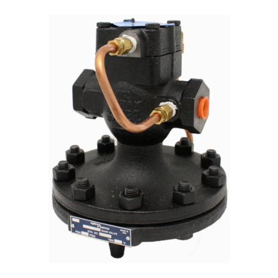
- Page 5 Para o funcionamento, a válvula 25P utiliza o próprio fluido que está passando pela válvula para atuar a sua abertura ou fechamento, de acordo com as oscilações das variáveis de controle do processo ou sistema.
- Page 6 4.4 Limites de Pressão e Temperatura Válvulas em ferro fundido: PMO - Pressão Máxima de Operação 17,3 bar g TMO - Temperatura Máxima de Operação 232 ºC Temperatura Mínima de Operação 0 ºC Vapor Saturado 17,3 Pressão, bar (g) Válvulas em aço carbono: PMO - Pressão Máxima de Operação 20,6 bar g TMO - Temperatura Máxima de Operação...
- Page 7 5. Instalação Nota: antes de realizar qualquer etapa da instalação do produto, observe os pontos descritos no tópico "Informações Gerais de Segurança", seção 3. Através do Manual de Instalação e Manutenção, plaqueta de identificação do produto e Folha de Informação Técnica, verifique se o produto está adequado para a instalação desejada.
- Page 8 Instale uma válvula de esfera no tubo de equilíbrio para que ela possa ser fechada quando for necessária a manutenção do regulador. Para permitir um controle preciso do regulador de pressão, um manômetro deve ser instalado o mais próximo possível da tubulação de saída. Recomenda-se a instalação de uma válvula de by-pass, para que seja feita a manutenção da válvula sem interromper o funcionamento do equipamento.
- Page 9 Filtro instalado numa linha de vapor ou gás Filtro instalado numa linha de líquido 6. Comissionamento Certifique-se que todas as válvulas de bloqueio estão fechadas. Vire o parafuso de ajuste do controle piloto no sentido anti-horário até que a mola esteja solta.
- Page 10 7. Correção de Defeitos Sintomas Possíveis Causas Solução Sujeira ou obstrução Solte o parafuso de ajuste. Remova entre a sede e a cabeça as conexões dos tubos. Retire a cabeça Fornecimento de da sede da válvula do piloto e o conjunto da sede para pressão pode estar sua limpeza ou reposição.
- Page 11 8. Manutenção Nota: antes de realizar qualquer etapa da manutenção do produto, observe os pontos descritos no tópico "Informações Gerais de Segurança", seção 3. Aviso As juntas grafitadas contém um fino anel de suporte em aço inoxidável, o qual pode causar ferimentos se não manuseado e eliminado cuidadosamente.
- Page 12 11/16“. • Se for constatado que a cabeça e a sede sofreram desgaste, ambos devem ser substituídos por um conjunto de reposição original Spirax Sarco. 8.3 Inspeção dos diafragmas da válvula principal • Gire o parafuso de ajuste (A) no sentido anti-horário para piloto P e PA ou sentido horário para pilotos BP e BPA até...
- Page 13 8.5 Inspeção e reposição do diafragma da válvula principal (1/2” a 4") • Retire a conexão (G) da tubulação de cobre. • Retire os parafusos do diafragma (X). • Isto permitirá que a câmara inferior do diafragma (W) seja retirada. •...
- Page 14 1/2" e 1.1/4" e 2.1/2" e 1" 2" 4" 6" 3/4" 1.1/2" 3" A (mm) 10,4 IM-G10-02...
-
Page 15: Peças De Reposição
9. Peças de Reposição Peças de Reposição As peças de reposição disponíveis estão marcadas em linhas sólidas na figura abaixo. Prato do Diafragma Conjunto da Tampa 2, 10 Conjunto de Juntas da válvula 6, 10, 19, 31 Conjunto da Haste da válvula 6, 8, 14, 18 Conjunto Mola da válvula 7, 9, 10... -
Page 16: Informações Complementares
SelfSense, em ferro fundido, diâmetro 2". 10. Informações Complementares Para auxiliar os usuários de sistemas de vapor em todo o Brasil, a Spirax Sarco possui diversos serviços de apoio técnico. Eles foram estruturados para eliminar definitivamente as perdas energéticas na indústria. - Page 17 1.753.000.085 IM-G10-02 BR Issue.00 25P and 25PSS Installation and Maintenance Instructions 1. Warranty 2. Information about Valve returns 3. Safety Information 4.Technical Information 5. Installation 6. Start up 7. Troubleshooting 8. Maintenance 9. Spare Parts IM-G10-02...
-
Page 18: Warranty
The only Spirax Sarco obligation with the warranty is to fix or replace any product that we find a problem. Spirax Sarco reserves the right to inspect the product final customer installation or to require the return of the product with shipping prepaid by the customer. -
Page 19: Safety Information
3. Safety Information The safe operation of the products described in this Installation and Maintenance Instructions only can be guaranteed if the products are properly installed, started up and maintained by qualified personnel, according the operation instructions. Safety and installation information for the pipeline and the factory, as well as the appropriated use of tools and safety equipment should be obeyed too. - Page 20 3.16. Returning products Customers and stockists are reminded that under EC Health, Safety and Environment Law, when returning products to Spirax Sarco they must provide information on any hazards and the precautions to be taken due to contamination residues or mechanical damage which may present a health, safety or environmental risk.
-
Page 21: Technical Information
For the operation, the 25P valve uses its own fluid which is passing through the valve to control the valve opening or closing, according to the variations of the controlled variables of the system or process. - Page 22 4.4 Pressure and temperature limits Cast Iron Valves: Maximum Operating Pressure 17,3 bar g Maximum Operating Temperature 232 ºC Minimum Operating Temperature 0 ºC Saturated Steam Vapor Saturado 17,3 Pressão, bar (g) Pressure bar (g) Carbon Steel Valves: Maximum Operating Pressure 20,6 bar g Maximum Operating Temperature 316 ºC...
-
Page 23: Installation
5. Installation Note: Before actioning any installation observe the 'Safety information in Section 3. Referring to the Installation and Maintenance Instructions, name-plate and Technical Information Sheet, check that the product is suitable for the intended installation: Check materials, pressure and temperature and their maximum values. If the maximum operating limit of the product is lower than that of the system in which it is being fitted, ensure that a safety device is included in the system to prevent overpressurisation. - Page 24 Install a ball valve in the sensing tube so it can be closed when the valve maintenance is required. To allow accurate control of the pressure valve, a pressure gauge should be installed as close as possible to the valve, in the downstream pipeline. It is recommended the installation of a by-pass valve, to perform the valve maintenance without stopping the equipment operation.
- Page 25 Strainer installed on a steam or gas pipeline Strainer installed on a liquid pipeline 6. Start-up Make sure that all isolation valves are closed. Turn the adjustment screw counter-clockwise until the spring is released. Make sure that the spring stay on the vertical position and centralized in its chamber. Open the upstream steam trap isolation valve.
-
Page 26: Troubleshooting
7. Troubleshooting Symptoms Possible Causes Solution Loosen screw. Remove copper tubing Dirt or foreign material connections (J&L) With fluid in the between pilot valve valve, if it flows from the copper tubing seat and head remove the pilot head and the seat Reduced or assembly, clean and replace completely closed... -
Page 27: Maintenance
8. Maintenance Note: Before actioning any installation observe the 'Safety information in Section 3. Warning The graphite gaskets contain a thin stainless steel ring, which can cause injuries if not carefully handled and disposed. IM-G10-02... - Page 28 • To remove the head and seat assembly, unscrew the hexagon (M) using 11/16” hex wrench. • If it is found that either head or seat is worn, both should be replaced by a new original Spirax Sarco assembly. 8.3 Inspecting and replacing pilot valve diaphragm •...
- Page 29 • The 2 metal diaphragms (Y) can then be inspected for distortion or possible fracture as a result of unusual operation. • At the same time any dirt accumulation or foreign material should be removed from the lower diaphragm pilot case. •...
-
Page 30: Spare Parts
9. Spare Parts Spare Parts Available spare parts are shown with solid lines at the figure below. Diaphragm plate Cover assembly 2, 10 Main Valve gasket set 6, 10, 19, 31 Main Valve stem set 6, 8, 14, 18 Main Valve spring set 7, 9, 10 Main Valve relief and command set 16, 17... - Page 31 How to order Always order spares using the description given in the column headed “Spare parts” and inform the main characteristics of the valve. E.g.: 1 Lower chamber bolts set for the 25P self-operated reducing valve, in cast iron, 2” bore. IM-G10-02...
- Page 32 Anotações IM-G10-02...
Need help?
Do you have a question about the 25P and is the answer not in the manual?
Questions and answers