Advertisement
Table of Contents
Issue 2011-04-27
Product Description
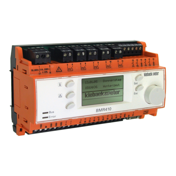
BMR410 Controller
Application
The BMR410 is a DDC controller for regulating,
controlling, monitoring and optimizing heating, ventilation
and air conditioning systems.
The BMR410 also has a fieldbus to allow for flexible
enhancement with input and output modules, as well as
with room control modules.
With an integrated Ethernet interface, the BMR410 has a
built in web server to facilitate visualization, remote
control and data backup over a web browser without the
need of any additional software.
Parameterization can be carried out using the BMRTool, the SI Tool or the PS4000.
Additional main features of the BMR410:
■
Native BACnet® in accordance with DIN EN ISO 16484-5 (BACnet® server functionality);
facilitates communication with the BMS by Ethernet or modem.
■
The BMRTool allows you to configure the controller quickly and easily. Plant macros are set to configure the
BMR410 completely, set the associated BMR software objects, configure the parameters and assign the input
and output signals.
■
Simple turn-knob operation with illuminated display
■
Weekly schedule and annual schedule
■
Trend data can be saves and visualized
■
Code keys for quick display and adjustment of plant values at different access levels;
customer-specific plaintext for every parameter
■
Can be operated in 12 languages (Czech, Dutch, English, French, German, Hungarian, Italian, Latvian, Polish,
Russian, Spanish and Swedish)
■
3 closed-loop control circuits for heating or 2 for ventilation, which can be extended by hardware and software
objects
■
Malfunction message logging with time and date
Content
Important Information Regarding Product Safety ..................................................................................................2
Item........................................................................................................................................................................3
Technical Data.....................................................................................................................................................3
Accessories (not included in delivery) .................................................................................................................4
Dimensions ..........................................................................................................................................................5
Connectable fieldbus modules.............................................................................................................................6
Connection...........................................................................................................................................................6
Fieldbus Power Supply ........................................................................................................................................8
Installation..............................................................................................................................................................9
Opening the Housing ...........................................................................................................................................9
Removal...............................................................................................................................................................10
Änderungen vorbehalten - Contents subject to change - Sous réserve de modifications - Reservado el derecho a modificación - Wijzigingen
voorbehouden - Con riserva di modifiche - Innehåll som skall ändras - Změny vyhrazeny - Zmiany zastrzeżone - Возможны изменения -
A változtatások jogát fenntartjuk - 保留未经通知而改动的权力
Kieback&Peter GmbH & Co. KG
Tempelhofer Weg 50, 12347 Berlin/Germany
Telefon: +49 30 60095-0, Telefax: +49 30 60095-164
www.kieback-peter.de, info@kieback-peter.com
Datasheet 2.70-10.411-01-EN
BMR410
Page
A
Advertisement
Table of Contents

Related Manuals for Kieback&Peter BMR410


Summary of Contents for Kieback&Peter BMR410
-
Page 1: Table Of Contents
BMS by Ethernet or modem. ■ The BMRTool allows you to configure the controller quickly and easily. Plant macros are set to configure the BMR410 completely, set the associated BMR software objects, configure the parameters and assign the input and output signals. ■... -
Page 2: Important Information Regarding Product Safety
Important Information Regarding Product Safety Safety Instructions This data sheet contains information on installing and commissioning the product "BMR410". Each person who carries out work on this product must have read and understood this data sheet. If you have any questions that are not resolved by this data sheet, you can obtain further information from the supplier or manufacturer. -
Page 3: Item
Issue 2011-04-27 Datasheet 2.70-10.411-01-EN Product Description BMR410 Item BMR410 DDC controller with operating function and integrated Web server for remote control Technical Data AC 110 V to 230 V AC ± 10%; 50 Hz to 60 Hz; 10 VA Nominal voltage... -
Page 4: Accessories (Not Included In Delivery)
Datasheet 2.70-10.411-01-EN Issue 2011-04-27 BMR410 Product Description Sensor Types Sensor Type Value Range 0 to 10 V 0 to 100% KP10 -50 to 150°C KP250 -50 to 150°C PT100 -50 to 350°C PT1000 -50 to 350°C Ni100 -50 to 150°C Ni1000 (DIN) -50 to 150°C... -
Page 5: Dimensions
Issue 2011-04-27 Datasheet 2.70-10.411-01-EN Product Description BMR410 Z180 Housing for wall mounting ■ Installation space: one row, 324 mm (18 HP); 1 BMR, 2 FBUs and 2 HP free Adapter frame for installing a BMR in the switch cabinet door ■... -
Page 6: Connectable Fieldbus Modules
Input/output modules ■ FBU410 ■ FBM(0)18 ■ FBM(0)24 ■ BMF400 (maximum 1 can be installed on the BMR410 using the cascade connection) ■ FBS51/04 (maximum 1 can be installed on the BMR410) Room control modules ■ DDC110-3 ■ DDC110S ■... - Page 7 Issue 2011-04-27 Datasheet 2.70-10.411-01-EN Product Description BMR410 Sensor and actuator connection 0..10V DC KP10 24V 0V Y 24V 0V b KP250 ϑ Fieldbus connection BMR410 BMR410 FBU410 FBS51/04 FBM(0)18 FBM(0)24 Fieldbus When connecting the fieldbus, use a cable of at least type JY(St)Y 2x2x0.8 Lg: two x two wires, twisted to a pair with plastic insulation and an electrostatic shield with a wire diameter of at least 0.8 mm.
-
Page 8: Fieldbus Power Supply
BMR410 Product Description Fieldbus Power Supply In the simplest case, the fieldbus module can be supplied with power from the BMR410. When JY(St)Y 2x2x0.8 Lg bus cables are used, the following maximum fieldbus lengths are possible: FBU and FBM modules... -
Page 9: Installation
Issue 2011-04-27 Datasheet 2.70-10.411-01-EN Product Description BMR410 Installation WARNING Danger of death by electrocution Mount or remove only when power is switched off. Opening the Housing When mounting or connecting the fieldbus module, it may be necessary to open the housing of the BMR410. -
Page 10: Removal
Datasheet 2.70-10.411-01-EN Issue 2011-04-27 BMR410 Product Description Removal WARNING Danger of death by electrocution Mount or remove only when power is switched off. Page 10 / 10...
Need help?
Do you have a question about the BMR410 and is the answer not in the manual?
Questions and answers