
Related Manuals for VDO Ocean Link


Summary of Contents for VDO Ocean Link
- Page 1 Installation and Operating Instructions Tachometer CAN Central Instrument Easy Link Satellite Gauge...
-
Page 2: Table Of Contents
Disposal ........... . 6 1. Ocean Link Tachometer ..... . . 7 2. -
Page 3: Safety Instructions
This product was developed, manufactured and tested in accordance with the basic safety requirements of EU Directives and the latest technological standards. Changing or tampering with a VDO product can affect safety. Therefore, the pro- duct may not be changed or tampered with. -
Page 4: On Power Supply
On intended use • This device is intended for use in vehicles and machines on land as well as in recreational ships (including non-classified commercial ships). Any other use is considered improper use and is prohibited. Improper use of the product can re- sult in personal injury or damage to property or the environment. -
Page 5: On Installation
On installation • The product should be installed by an expert who specializes in the installation of the product. If you install the product yourself, wear appropriate work clothes. Do not wear loose clothing that can become caught in moving parts. If you have long hair, wear a hair net. -
Page 6: If The Device Is Defective
Check all the functions of the newly installed device. If the device is defective • Never operate a defective device. • Give defective devices to your VDO dealer for testing. Maintenance and cleaning • The device does not contain any parts or components that require maintenance. •... -
Page 7: Ocean Link Tachometer
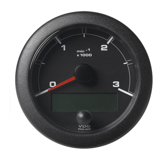
Basic Information Push-button menu key The VDO Ocean Link tachometer is a multifunctional instrument for indicating en- gine data, and is intended for use in navigation of sports ships. The tachometer shows the actual engine speed in operation, on the analogue scale. Further values and operating aids appear in the LCD. -
Page 8: Components
The supply schedule includes the following: • display unit • a set of parts for fixing the display unit • assembly and operating instructions 2.1 Accessories (not included in the supply schedule): • Ocean Link front bezels in various colours • Easy Link satellite gauges... -
Page 9: Functions Of The Tachometer
Functions of the Tachometer Displays: • Engine speed (indicated by means of a pointer) • Engine hours (indicated in LCD) • Engine oil pressure (indicated in LCD) • Transmission oil pressure (indicated in LCD) • Transmission oil temperature (indicated in LCD) •... -
Page 10: Displays And Setting Possibilites
Displays and Setting Possibilites 4.1 Basic Settings The basic settings necessary for perfect operation can be selected in the settings menu. These are obtained by pressing and holding the push-button key while switching on the power supply of the display. Selection of display unit (see p. -
Page 11: Setting The Inputs
4.1.3 Setting the inputs (config inputs) In this menu the following settings are possible: Selection of fuel quantity signal (see p. 9) Fuel tank signal: Selection of function of 4-20 mA transmitter (see p. 10) 4-20 mA input: Setting number of exhaust gas temperature Change boost amount: measured values (see p. -
Page 12: Selection Of The Function Of The 4-20 Ma Sensor
MEASURED RES: VAL: 85 SAVE VALUE FOR CAL. ? MEASURED RES: VAL: 85 SAVE VALUE FOR CAL. ? Keep key pressed TANK CALIBRATED 4.1.5 Selection of the function of the 4-20 mA sensor Select here which function the 4-20 mA water level sensor has. No display of water level Off: Display of fresh water level... -
Page 13: Selection Of The Displays
4.1.8 Selection of the displays (screens on / off) Select here which measured values are to be displayed in the normal operating mode. Here all measured values, with their ISO symbol, are displayed. YES: By selecting NO the measured value can be removed from the normal operating mode. -
Page 14: Main Functions
Main Functions The main functions of the VDO Ocean Link tachometer can be called by pressing the push-button key. Each time the key is pressed, the next measured value is dis- played. Engine hours Engine oil pressure Transmission oil pressure... -
Page 15: The Can Interface
INTERNAL in the settings menu. The CAN Interface The VDO Ocean Link tachometer receives data from a CAN 2.0 B interface. Data in the SAE J1939 format are transmitted on this interface. The parameter group numbers (PGN) of the data which the display receives are given in the table below. - Page 16 Display of battery voltage: Display Voltage Term.15 voltage Term.15 available? Display Voltage Term. 30 voltage Term.30 available? Display voltage measured by the indicator List of parameter groups used SAE J1939/71 Oct. 1998 Designation: Section no. PGN: ELECTRONIC ENGINE CONTROLLER #2 5.3.6 61443 ELECTRONIC ENGINE CONTROLLER #1...
-
Page 17: Installation Of The Tachometer
Installation of the Tachometer Before beginning, disconnect the negative terminal on the battery, otherwise you risk a short cir- cuit.. If the vehicle is supplied by auxiliary batteries, you must also disconnect the negative on these batteries! Short circuits can cause fires, battery explosions and damages to other electronic systems. - Page 18 0.5 ..6.5 mm 6.5...16.5 mm Please note that when you disconnect the bat- tery, all volatile electronic memories lose their input values and must be reprogrammed.
-
Page 19: Installation Of The Satellite Gauge
Installation of the Satellite Gauge Before beginning, disconnect the negative terminal on the battery, otherwise you risk a short cir- cuit.. If the vehicle is supplied by auxiliary batteries, you must also disconnect the negative on these batteries! Short circuits can cause fires, battery explosions and damages to other electronic systems. - Page 20 Fasten Retainer Nut Hand Tight Only Tachometer CAN Master Easy Link Easy Link Easy Link Gauge 1 Gauge 2 Gauge 3 ..max. 20 Gauges max. 20 m Cable Length Please note that when you disconnect the bat- tery, all volatile electronic memories lose their input values and must be reprogrammed.
-
Page 21: Electrical Installation (Pin Assignment)
Electrical Installation (pin assignment) Pin: Assignment: Color Satellite Bus Power red/white Analogue input 4-20 mA blue/white Analogue input 0-200 Ohm grey/white Satellite Bus Ground / Signal Ground black/grey not connected purple Term. 31 (GND) black Term. 30 (Battery power) Satellite Bus yellow CAN high green... -
Page 22: Technical Data
CE according to EMV 83/336/EEC Data input: CAN 2.0 B; SAE J1939 analogue 4-20 mA analogue 0-200 Ohm Data output: VDO Easy Link satellite bus Dimensions: 85 mm built-in diameter 73 mm built-in depth (including cable) Connection: Delphi plug, GT 150 sealed... - Page 23 E-mail: industrial@vdo.com www.vdo.com VDO - A trademark of the Continental Corporation The reproduction, distribution and utilization of this document as well as the communication of its contents to others without express authorization is prohibited. Offenders will be held liable for the payment of damages. All right reser- ved in the event of the grant of a patent, utility model or design.
Need help?
Do you have a question about the Ocean Link and is the answer not in the manual?
Questions and answers