Advertisement
Tech Support 1-800-265-1818
http://usa.vdo.com
Gauge Installation:
1. Select the desired mounting location of the instrument.
2. Depending on your mounting configuration, it might be
necessary to program the gauge before installation (for
example, if you will not have access to the button on the
lens).
3. Mount the gauge and secure with the included hardware.
Wiring the Gauge:
1. Route wires from the instrument to:
(a) Battery (+) constant power after the fuse box or user
supplied in line fuse (5 amp, fast blow) to terminal "+"
(b) Battery (+) switched power after the fuse box or user
supplied in line fuse (1 amp, fast blow) to terminal "L"
(c) Light switch after the fuse box, or user supplied in line
fuse (1 amp) and switch to light bulbs
(d) Ground location not shared with other electronics
(such as battery (-) negative terminal or direct to
chassis) to terminal "-" and light bulbs.
(e) Speed signal source to terminal "W"
(f) Optional. Terminal "I" for (+) voltage to speed sensor.
Terminal
+
I
L
W
-
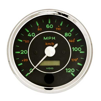
356 Gauge Speedometer 100mm
Description
Constant power (12v or 24v)
Optional - power for speed sensor
Switched Power
Speed sensor input
Ground
Instruction Sheet # A2C
Read these instructions thoroughly
before installation. Do not deviate
from assembly or wiring diagram.
Always disconnect battery ground
before
connections.
Programming the speedometer:
Rev 02-2024
making
any
electrical
Page | 1
Advertisement
Table of Contents

Related Manuals for VDO 356


Summary of Contents for VDO 356
- Page 1 356 Gauge Speedometer 100mm Tech Support 1-800-265-1818 Instruction Sheet # A2C Rev 02-2024 http://usa.vdo.com Gauge Installation: Read these instructions thoroughly before installation. Do not deviate 1. Select the desired mounting location of the instrument. from assembly or wiring diagram. 2. Depending on your mounting configuration, it might be...
- Page 2 356 Gauge Speedometer 100mm Tech Support 1-800-265-1818 Instruction Sheet # A2C Rev 02-2024 http://usa.vdo.com and display that pulse count in the LCD Calibrating the speedometer can be accomplished by one display for a few seconds. The of three methods. autocalibration will complete when the needle does a full sweep and returns to “0”.
- Page 3 This warranty applies to the first retail purchaser and covers only those products exposed to normal use or service. Provisions of this warranty shall not apply to a VDO product used for a purpose for which it is not designed, or which has been altered in any way that would be detrimental to the performance or life of the products, or misapplication, misuse, negligence or accident.
Need help?
Do you have a question about the 356 and is the answer not in the manual?
Questions and answers