
Related Manuals for Dino lift DINO 185XTS


Summary of Contents for Dino lift DINO 185XTS
- Page 1 DINO 185XTS ® OPERATING INSTRUCTIONS Manufacturer Dealer Raikkolantie 145 FI-32210 LOIMAA T. +358 2 762 5900 F. +358 2 762 7160 dino@dinolift.com www.dinolift.com...
- Page 3 ORIGINAL OPERATING INSTRUCTIONS VALID FROM SERIAL NUMBER 540016 ...
-
Page 4: Table Of Contents
TABLE OF CONTENTS OPERATION AND SAFETY ....................7 EU DECLARATION OF CONFORMITY ..............7 REACH DIAGRAM ..................... 8 DIMENSION DRAWING .................... 9 TECHNICAL SPECIFICATION .................10 Example of the machine’s nameplate ..............10 ... - Page 5 16.1 Transporting on flatbed of a vehicle ..............41 16.2 Lifting .........................42 16.3 Towing .......................43 NOTES ........................45 SERVICE AND MAINTENANCE ..................46 INSTRUCTIONS FOR SERVICE AND MAINTENANCE ........46 18.1 General service instructions ................46 ...
- Page 6 28.3.3 Thorough inspection of the electric system ..........82 28.3.4 Thorough inspection of the steel structures ..........83 28.4 EXTRAORDINARY INSPECTION ..............85 FAULT FINDING ....................86 29.1 Error codes of the electric control system ............86 ...
-
Page 7: Operation And Safety
Loimaa, Finland to draw up the Technical Construction File declares that DINO 185XTS Access Platform no YGC185XTSD05400XX is in conformity with the provisions of Machinery Directive 2006/42/EC as amended and with national implementing legislation and also fulfils the requirements of the following EEC directives: Low Voltage Directive (2006/95/EC), directive (2000/14/EC), and EMC Directive (2004/108/EC). -
Page 8: Reach Diagram
2. REACH DIAGRAM... -
Page 9: Dimension Drawing
3. DIMENSION DRAWING... -
Page 10: Technical Specification
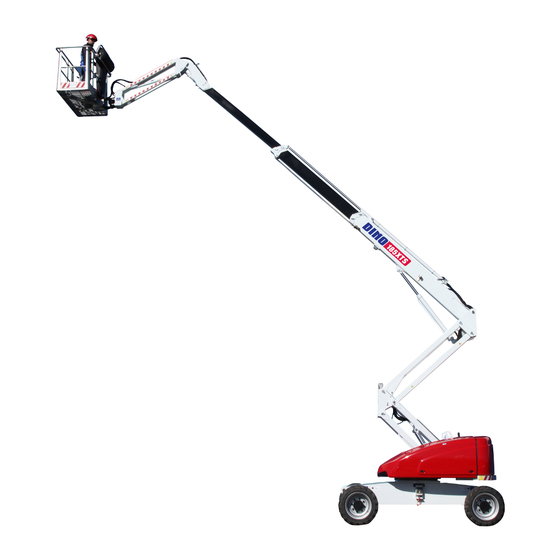
4. TECHNICAL SPECIFICATION Max. working height (18.5 m) Max. platform height (16.5 m) Max. outreach (11.7 m) Boom rotation continuous Platform rotation 180° Work area refer to the reach diagram Swing radius (1.75 m) Transport width (2.29 m) Transport length driving / transportation 7.17m / 5.27m Transport height (2.56 m) -
Page 11: General Description Of The Machine
4.2 General description of the machine The denominations of the machine’s essential parts and concepts, which are used later in these instructions, are described on this page. Turning Left counter-clockwise Platform control Right Turning centre (UCB) clockwise Boom extension 3 Platform Boom extension 2 Boom extension 1... -
Page 12: Description Of The Machine's Intended Use
4.3 Description of the machine’s intended use The Dino 185 XTS Access Platform is exclusively intended for lifting and transferring people and tools and acting as a work platform to the limit of its load-bearing capacity and reach (see Technical specifications and Reach diagram). - Page 13 Do not use ladders, steps or other similar equipment on the platform. Never throw any objects from the platform. The lift must not be used for transferring goods or persons between different floors or working levels. Never disable the operation of any safety device. ...
- Page 14 Stepping on or off the platform in motion is prohibited. Familiarise yourself with the terrain before starting the operation. The max. allowed inclination of 20 ° must not be exceeded while transferring the lift. If the inclination is more than 5°...
- Page 15 The device must not be altered without the manufacturer’s consent nor used under conditions that do not meet the requirements set by the manufacturer. The operator must be given instructions and consent from the manufacturer for all such specific work methods or conditions that the manufacturer has not explicitly defined.
-
Page 16: Inspections
INSPECTIONS A thorough inspection of the lift must be carried out at least once every twelve (12) months. The inspection shall be carried out by a technically trained person who is familiar with the operation and structure of the lift. Draw up a protocol of the inspections and always keep it with the unit stored in the space reserved for it. -
Page 17: Daily Inspection (Start-Up Inspection)
7. DAILY INSPECTION (START-UP INSPECTION) To be always performed at a new worksite and in the beginning of every working day. The inspection is performed by the user. In the inspection attention shall be paid to the following issues: Establish the load-bearing capacity of the ground (see point “General safety regulations”). - Page 18 Check the operation of the control system for platform load. Check that, when there is no load on the platform, both the green and the yellow LED indicators are illuminated (see point “Operation of the safety devices”). Check the element of the Diesel engine cooler for cleanliness...
-
Page 19: Worksite Inspection
8. WORKSITE INSPECTION 1. General information Is the lift suited for the intended job? Is the performance of the lift sufficient for the job? (reach, loadability etc.) Is the position of the lift safe? Is the terrain suitable for using the lift (evenness and load-bearing capacity)? Is the lighting on the worksite sufficient? Permissible ground pressure for different soil types Soil material... -
Page 20: Operation Of The Safety Devices
9. OPERATION OF THE SAFETY DEVICES Lifting the boom/ articulated arms (RK3) The safety switch RK3 prevents driving at the maximum speed once the boom or the articulated arms are lifted from the limit switch. The switch is located on the transport support. -
Page 21: Platform Load Control (Mrv)
9.4 Platform load control (MRV) The max. allowed platform load is 250 kg. The platform load control device (MRV) prevents all the movements by turning off the power unit if the platform load exceeds 285 kg. The platform load control device alarms of excess load on the platform in accordance with the adjacent table. - Page 22 error LED User interface Connector alarm LED reset/calibratio n LED power on MRV: LED signal lights under the work platform Fault LED (Red) System failure Alarm LED (Red) Load alarm o overload situation o the platform has clashed with an obstacle ...
-
Page 23: Inclination Sensors Rk30A And Rk30B
9.5 inclination sensors RK30a and RK30b The inclination sensor prevents transport driving, if the lift is inclined more than 5°, and either the boom or the articulated arms have been lifted or the boom extensions have been extended. The signal light H17 and the buzzer indicate that the inclination of the lift is greater than 5°. -
Page 24: Operating Controls
10. OPERATING CONTROLS 10.1 LCB – CONTROLS IN THE CHASSIS PANEL – XTS Diesel – Signal light for battery recharging Start/stop, engine Diesel – Signal light for oil pressure Operating switch for emergency descent Diesel – Signal light for overheating system Diesel –... -
Page 25: Ucb - Operating Controls On The Platform - Xts
10.2 UCB – OPERATING CONTROLS ON THE PLATFORM – XTS Glowing of Diesel engine, signal light JSR Operating lever for transfer drive Electric system failure Lifting and lowering the articulated arms Low fuel Boom extensions in and out Pedal depressed Lifting and lowering the jib arms Chassis inclined more than 5°... - Page 26 Turning the boom clockwise – Turning the wheels counter-clockwise Boom Drive Lifting / Forward / lowering Backward JSL, control lever for boom JSR, control lever for driving DMS1 DMS1, Foot pedal on the platform (dead-man-switch)
-
Page 27: Measures To Be Taken In Case Of Emergency/At Risk Of Losing The Stability
11. MEASURES TO BE TAKEN IN CASE OF EMERGENCY/AT RISK OF LOSING THE STABILITY Reduced stability can be caused by a fault in the lift, the wind or other lateral force, insufficient stability of the standing base or too uneven terrain. In most cases one sign of reduced stability is the inclination of the lift. -
Page 28: Starting Up
3. Establish the reason why the energy supply was interrupted. IN CASE OF MALFUNCTION, WHEN EVEN THE EMERGENCY DESCENT SYSTEM IS NOT OPERATIONAL 1. If the emergency descent system does not operate, try to warn other personnel present on the site or call for help so that the normal operation of the emergency descent system can be resumed, for example, by changing the battery or by making the lift operative by some other means so that the person on the platform can be lowered safely down. -
Page 29: From The Platform Control Panel Ucb
If the engine is cold, the glowing will occur automatically. The signal light for glowing H9 will remain illuminated until glowing of the engine is completed. As soon as the light is switched off, the engine is ready to start. 7. - Page 30 Make sure that, while the engine is running, only the signal light H21 “Electric system active”, and the lights H23 and H24, which indicate the allowed direction of rotation of the turning device, remain illuminated. Note! If the engine is not running, and the movements are not actuated, the electric system goes into sleep mode in about 30 minutes.
-
Page 31: Transferring, Driving And Steering
12.3 Transferring, driving and steering Driving the lift with the platform raised is only allowed on an even, firm and level surface. Fast transport driving is only allowed in the transport position. The boom is parallel to the chassis, the boom extensions are fully retracted, the boom has been lowered, and the jib arms have been lowered near to the ground. -
Page 32: Steering
NOTE! If you keep the foot switch depressed for 10 seconds without activating any of the movements, the signal light H16 will start flashing, and you must activate the foot pedal anew. Select the desired speed range (slow/fast) using switch S22. The high-speed position is enabled only when the boom is in the transport position (see point “Operation of the safety devices”) ... -
Page 33: Operating The Boom From The Platform Control Centre Ucb
allowed inclination has been exceeded. The lift is equipped with a system that indicates the safe turning direction of the turning device so that the boom system can be moved to the transport position in case the inclination exceeds the allowed value . - Page 34 Turning device JSL - to the left / Stepless clockwise / counter- right adjustment clockwise Articulated arms up / Stepless JS2 - up / down down adjustment Boom extensions in / Stepless JS3 - up / down adjustment Stepless JS4 - up / down Jib arms up / down adjustment Turning the platform...
-
Page 35: Operating The Boom From The Chassis Control Centre Lcb
12.4.2 Operating the boom from the chassis control centre LCB The power switch Q1 in the LCB centre must be turned to the left: Chassis control centre. To operate the movement, select the speed range using the switch S23, and keep it selected when you use the operating switch for this movement. -
Page 36: Socket Outlets On The Platform
12.5 Socket outlets on the platform. 1. The socket outlets (2 pcs.) that are intended for powering electric tools, are located on the platform, below the UCB centre. (230V/ 50Hz/ 16A). 2. The power supply cord, fault current safety switch and cable reel stand are located on the chassis (see attached pictures). - Page 37 4. Move the platform to the work location. The platform movements can be operated with continually adjustable speed from the platform control panel (not from the chassis control panel). The movements can also be operated simultaneously. 5. DO NOT TAKE ADDITIONAL LOAD IN THE UPPER POSITION! 6.
-
Page 38: Emergency Descent System
9. When leaving the lift Drive the lift to a safe position, preferably to the transport position. Make sure that the lift will stay in position. Avoid parking on a gradient (if necessary, use chocks to prevent the machine from breaking loose). ... -
Page 39: Using The Emergency Descent System
13.2 Using the emergency descent system 13.2.1 From the chassis control centre LCB 1. Start the emergency descent motor from the pushbutton S14 (keep it depressed throughout the operation). 2. Retract the boom extensions completely using the operating lever JS3. 3. -
Page 40: Special Instructions For Winter Use
14. SPECIAL INSTRUCTIONS FOR WINTER USE the lowest allowed operating temperature of the lift is -20 °C. Allow the automatic glowing system to finish its operation before starting the Diesel engine. If the temperature is below zero, let the engine run for a few minutes before starting the movements. -
Page 41: Preparing The Lift For Transport
16. PREPARING THE LIFT FOR TRANSPORT 16.1 Transporting on flatbed of a vehicle 1. Bring the boom into the transport position (see point “Dimension drawing”). In the transport position, the boom extensions are fully retracted, the boom is at its lowest position, the articulated arms have been lowered, and the jib arms have been lowered near the ground. -
Page 42: Lifting
Remember to tie down and lift the load by correct points (lugs marked by decals in the frame and the boom). Load binding lug Lifting lug 16.2 Lifting Lifting the device is allowed by the designated points only. There are marked lifting lugs on the chassis (4 pcs.) and in the turning device (2 pcs.). -
Page 43: Towing
16.3 Towing The unit must not be towed faster than 1.2 km/h, or for more than 3 minutes without a pause. The following measures shall be carried out before towing the lift: o Bring the boom system to the transport position for towing. If the fault in the Diesel unit prevents the moving of the boom, the lift must be driven to the transport position using the emergency descent system. - Page 44 RELEASING THE PUMP FOR TOWING Washer Bolt REMEMBER TO RESUME THE OPERATION OF THE BRAKES BY PUTTING THE WASHERS (4 PCS.) BACK IN PLACE AFTER THE TOWING. REMEMBER TO DEACTIVATE THE FREE CIRCULATION OF THE PUMP BY TIGHTENING THE BOLTS (2 PCS.). In the event of emergency, if an obstacle prevents the boom from being driven to the transport position, exercising particular caution, and avoiding abrupt movements, tow the unit to a place, where the...
-
Page 45: Notes
17. NOTES... -
Page 46: Service And Maintenance
SERVICE AND MAINTENANCE 18. INSTRUCTIONS FOR SERVICE AND MAINTENANCE 18.1 General service instructions Carry out the servicing and inspection of the lift in accordance with the instructions. When it comes to more demanding repair works or readjustment of the limit switches, consult a specialist or contact the distributor or the manufacturer of the lift. -
Page 47: Service And Inspection Instructions
18.2 Service and inspection instructions 1. The first service after 20 hours of operation Change the pressure and return filter elements. Check the wheel bolt for tightness – 360 Nm (M18, 32 pcs.). Check the attachment bolts of the steering axle for tightness – 520 Nm (M20, 2 pcs.). ... - Page 48 NOTE THE PERFORMANCE OF THE PERIODIC SERVICING AND THE INSPECTIONS IS ABSOLUTELY MANDATORY, BECAUSE THEIR NEGLIGENCE MAY IMPAIR THE OPERATIONAL SAFETY OF THE LIFT. NOTE THE GUARANTEE WILL NOT REMAIN VALID, IF THE SERVICING AND THE PERIODIC INSPECTIONS ARE NOT PERFORMED.
-
Page 49: Lubrication Instructions
LUBRICATION INSTRUCTIONS Obscured greasing nipples... -
Page 50: Lubrication Table
19.1 Lubrication table Object Number of Every Every Lubricant objects hours mont 1. Lift cylinder bearing ESSO Beacon EP2* 2. Chain-wheel bearings of ESSO Beacon EP2* the boom extension 3. Bearings of platform ESSO Beacon EP2* levelling cylinder 4. Bearings of jib cylinder ESSO Beacon EP2* 5. -
Page 51: Long-Term Storage
20. LONG-TERM STORAGE Clean the machine carefully, lubricate it and apply protective grease to it before putting it into storage for a longer period of time (see point “Lubrication plan”). Repeat the cleaning and lubrication procedures while resuming the operation. The periodic inspections must be executed following the steps described in the instructions (see point “Inspections”). -
Page 52: Axles
21.3 Axles Steering/oscill Fixed axle NOTE ating axle DANA DANA Axle type MO211S40 MO211S40 Friction lock Lockable Differential lock 45 % 100 % Reduction gear 1:2.28 Differential 8:35 8:35 Planetary gear Reduction gear SAE85W90 SAE85W90 API Change interval 1000 h API GL-5 GL-5 SAE85W90... -
Page 53: Load Holding And Load Regulation Valves
22. LOAD HOLDING AND LOAD REGULATION VALVES 22.1 Location of the load regulation valves Load regulation valve of Load regulation valve of the boom cylinder the jib cylinder oscillation Load regulation valve of the arms cylinder/levelling cylinder Load regulation valve of the lifting cylinder Oscillation lock of the axle load regulation valve... -
Page 54: Checking The Operation Of The Load Regulation Valves
22.2 Checking the operation of the load regulation valves Checking the operation of the load regulation valves of the oscillating axle locking. Drive the boom of the lift to the transport position on a level surface, and ensure that the boom is exactly parallel to the chassis. (0° or 180°). ... -
Page 55: Service Instructions For The Load Regulation Valves
Observe the cylinder for a few minutes and repeat the measurement. See point “Location of the load regulation valves”. 22.3 Service instructions for the load regulation valves MAKE SURE THAT THE WORK PLATFORM, THE JIB ARMS, THE BOOM EXTENSIONS AND THE ARTICULATED ARMS HAVE BEEN SUPPORTED IN A POSITION IN WHICH THE LOAD DOES NOT REST ON THE STRUCTURE UNDER REPAIR/SERVICED. -
Page 56: Levelling System Of The Work Platform
23. LEVELLING SYSTEM OF THE WORK PLATFORM The levelling system of the platform is based on the so-called slave-master cylinder system: The slave cylinder located under the platform is controlled by a master cylinder. The work platform keeps its level position only if the valves in the system are tight. ... -
Page 57: Calibration Of The Control Sensor For The Platform Load
24. CALIBRATION OF THE CONTROL SENSOR FOR THE PLATFORM LOAD Note! Calibration of the control sensor for the platform load requires a TEACH IN tool. (Dino id:48.19044) Contact the seller of the lift. 1. Switch on the power to the lift; a green LED will be illuminated in the sensor (will be lit continuously until activation, after which starts flashing). -
Page 58: Dpf- Diesel Particle Filter (Option)
9. Disconnect the adjusting device from the sensor. 10. The alarm function is now active. (If the alarm function has not yet been activated, pull the platform downward lightly with your hand.) 11. Lift the weight off from the platform for at least 4 seconds (lags of the sensor), then replace the weight, and check that the light will be turned on. -
Page 59: Regular Servicing
26. REGULAR SERVICING 26.1 Schedule for regular servicing Under normal circumstances, the regular service of the lift shall be carried out at intervals of 11-12 months. Under demanding conditions where moisture, corrosive substances or corrosive climate may speed up the deterioration of the structure and induce malfunctions, the inspection must be performed more often and the influence of corrosion and malfunctions must be reduced by using appropriate protective substances. -
Page 60: Changing The Hydraulic Oil And The Filters
26.2.2 Changing the hydraulic oil and the filters Retract the cylinders of the boom system completely (transport position). Drain off the hydraulic oil tank via the drain plug (see adjacent picture). Clean and rinse the oil tank with suitable agent. ... -
Page 62: Hydraulic Hoses, Connectors And Pipes
26.2.3 Hydraulic hoses, connectors and pipes Visually check the condition of the hoses, connectors and pipes. Change any hoses with surface damage, cracks or chafing. NOTE! The explosion- proof protective sleeve must be renewed, if it is damaged by chafing. ... -
Page 63: Checking The Boom Cylinders
Filling Draining Checking the oil level 26.2.5 Checking the boom cylinders NOTE DRIVE THE BOOM SYSTEM INTO A POSITION, IN WHICH IT IS SAFE TO CHECK THE CYLINDER. Extend the lifting cylinder of the boom from the operating controls on the chassis control panel (LCB). -
Page 64: Inspecting The Boom And The Chassis
26.2.6 Inspecting the boom and the chassis 26.2.6.1 Checking the structures of the boom Visually check the platform, its attachment, the articulated arms and the boom with the telescope retracted. Check the boom joints and slide pads/plays, and as necessary, eliminate the slide pad play so that the boom extensions will move in the middle of the boom, and do not chafe against the sides. - Page 65 Extend and retract the boom extensions several times after the readjustment. Return the boom extensions to the measuring position, and repeat the measurement. Check the attachment of the unloaded chain (in the picture, red) by pulling it with your hand.
- Page 66 26.2.6.3 Checking the structure of the turning device Visually check the turning device – in particular its welded seams, and the attachment points of the joints and the turning bearing. Lubricate to turning bearing and the gear ring (see point “Lubrication instructions”). NOTE Do not press too much grease into the turning bearing, as the gaskets of the bearing might get out of position.
- Page 67 Location of the limit switches RK18 RK16 Socket outlets on the platform (1 pc.) o Load control system for the platform MRV Safety limit switches on the turning device (2 pcs.) o Sensor for the turning device position RK2 o Measuring sensors for inclination RK30a and RK30B Location of the safety limit switches...
-
Page 68: Checking The Operation Of The Load Control System For The Platform (Mrv)
26.2.7 Checking the operation of the load control system for the platform (MRV) Familiarise yourself with the operation of the load control system for the platform in point Operation of the safety devices/load control system for the platform. Table: alarm from the load control device for the platform Weight Signal light Sound signal... - Page 69 6. The lift's normal operation shall resume, when the weights are removed from the work platform. Check once more that when the work platform is empty, the GREEN LED is flashing, and the ORANGE LED is continuously illuminated. If the load control system for the platform does not operate properly, the sensor must be calibrated by means of the TEACH IN tool.
-
Page 70: Measuring The Pressure
26.2.8 Measuring the pressure Boom movements o Connect the pressure gauge to the measuring connector. The oil must be at the operating temperature (40 - 60 °C) during measuring of the pressure. if you have to readjust the pressure, secure the new setting with a seal. ... -
Page 71: Check The Operating Controls On The Work Platform (Ucb) And In The Lower Control Centre (Lcb)
26.2.9 Check the operating controls on the work platform (UCB) and in the lower control centre (LCB) check the overall condition of the electric appliances inside the box and spray with moisture repellent, if necessary check the cables and the tightness of the cable clamps ... - Page 72 4. At intervals of 2 years (refer to the operating instructions for the engine that are included in the delivery for more detailed information) Replace the V-belt Replace the glow plug Deutz - location of service objects Pre- Engine oil filter/water filter...
-
Page 73: Check The Anti-Corrosive/Paint Coat
26.2.12 Check the anti-corrosive/paint coat Check all the painted steel constructions, in particular the load-bearing structures and welded seams for any damage in the paint coat. Grind off any rust and repaint as necessary. Check the box-type structures with anti-corrosion coating and renew the treatment if necessary, using e.g. -
Page 74: Test Loading Instructions For Regular Inspection
27. TEST LOADING INSTRUCTIONS FOR REGULAR INSPECTION Drive the lift to a firm, level and even surface. 1. Drive the lift to the transport position. Lift the jib arms slightly. Be careful that the platform bottom does not hit the ground. 2. - Page 75 NOTES...
-
Page 76: Inspection Instructions
28. INSPECTION INSTRUCTIONS All lifting equipment and lifting gear used at a construction site must always be inspected before use. The lifts and related lifting gear used on a work site shall be subjected to a regular maintenance inspection; if possible once a week. Keep a journal of any notable shortcomings and defects observed and advise the foreman of them. -
Page 77: Sample Of Inspection Protocol For The Access Platform
28.1.1 Sample of inspection protocol for the access platform Continuous... -
Page 79: Monthly Inspection (Maintenance Inspection)
28.2 MONTHLY INSPECTION (MAINTENANCE INSPECTION) The inspection shall be performed by a person who is very familiar with the lift. Task list for inspection: 1. Perform the measures of the daily inspection (see point “Daily inspection” i.e. “Start- up inspection”). 2. -
Page 80: Annual Inspection (Regular Inspection)
28.3 ANNUAL INSPECTION (REGULAR INSPECTION) This inspection shall be performed by a skilled technician or an expert inspection body with documented evidence of competence (see point “Inspections”). In the inspection special attention has to be paid to the condition of the steel structures, the safety devices and the operating system. - Page 81 Load regulation valve of the boom cylinder Operating from the lower control panel (LCB), lift the boom and extend the boom extensions slightly; leave the boom in this position for about 5 minutes. Keep under scrutiny that the boom extensions do not retract by themselves. Load regulation valve of the articulated arms cylinder ...
-
Page 82: Thorough Inspection Of The Electric System
Hoses Check that the hoses do not show any chafes or leaks, and that they are properly fastened. Pipes Check that there are no dents, leaks, traces of corrosion or chafing at the clamps. Check that the pipe clamps are properly fastened. Connectors ... -
Page 83: Thorough Inspection Of The Steel Structures
28.3.4 Thorough inspection of the steel structures Check the attachment points of the hydraulic cylinders. Check the condition of the lifting cylinder bearings and pins and the locking of the pins. Check the condition of the articulated arm cylinder bearings and pins and the locking of the pins. - Page 84 Check the condition of the platform's floor plate. Check that the bearer of the platform does not show signs of notable buckles or deformations. Checking all the protective covers Check the attachment of the protective covers on the chassis. ...
-
Page 85: Extraordinary Inspection
After the operational tests, make sure that the test loading has not caused any defects, such as fractures or permanent deformations of a dangerous nature, on the steel structures or other loaded parts. draw up a protocol of the regular inspection with following articles: 1. -
Page 86: Fault Finding
29. FAULT FINDING 29.1 Error codes of the electric control system The signal light H12 in the platform control centre UCB, and the lower control centre LCB H11 indicate the faults in the electric control system by flashing an error code. ... -
Page 87: Error Codes Of The Control System For The Transmission
29.1.2 Error codes of the control system for the transmission The error codes of the control system for the transmission will not be reset until the fault has been eliminated. The error codes of the control system for the transmission will be shown when the operating controls are in the position 0, and the engine is running. -
Page 88: Fault Finding Table
29.2 Fault finding table FAULT REMEDY 1. Engine does not start, none of the signal lights is illuminated. Key switch Q1 or mains switch BMS is Turn on the switches. switched off. Fuse F1 blown. Fuse in the control centre LCB has blown, replace the fuse. - Page 89 FAULT REMEDY 5. None of the platform movements is operational, although the engine is running. Key switch Q1 in the main centre – platform Select the correct operating location using control centre the switch Q1. / lower control centre is in wrong position. Platform control centre: Pedal (DMS) is not Re-activate the pedal, and active.
- Page 90 FAULT REMEDY 7. Boom drifts slowly downwards The load regulation valve leaks. Remove and clean the valve. Check the condition of the o-rings. Carefully install the valve in place. If necessary, replace the valve (see point “Load regulation valves”). 8. Boom cannot be lifted Too much load on the platform, check the signal light.
- Page 91 FAULT REMEDY 13. Drive system is not operational, although the engine is running Key switch Q1 in the main centre – platform Select platform control centre. control centre/ lower control centre is in wrong position. Pedal (DMS) is not active. Re-activate the pedal, and check that the signal light is...
-
Page 92: Diagrams And Components
DIAGRAMS AND COMPONENTS 30.1 ELECTRIC SAFETY COMPONENTS 540001 30.1.1 CHASSIS CONTROL CENTRE (LCB), RELAYS SR4: SAFETY RELAY FOR EMERGENCY STOP CIRCUIT SR4 switches off the control voltage from the engine. The safety relay operates if the emergency stop buttons in the platform and lower control centres are in their upper position, the chain limit switch RK7 is not active, and there is no overload on the platform. -
Page 93: Limit Switches And Safety Devices
S11: START SWITCH OF THE EMERGENCY DESCENT SYSTEM Controls the solenoid for the emergency descent unit which starts the unit and supplies the control voltage to the control levers while the the emergency descent system is in operation. H17: SIGNAL LIGHT Indicates operation of the inclination alarm. -
Page 94: Other Markings
Disconnects the emergency descent circuit, if the platform is overloaded. Warns by switching on the signal light H19 when the overload situation is approached. Alarms by buzzer H18 and flashing of signal light H19 in the event of overloading. 30.1.5 OTHER MARKINGS M2: EMERGENCY DESCENT MOTOR 12VDC MAX. -
Page 95: Dino 185 Xtc Electric Components 540003
540003 30.2 DINO 185 XTC ELECTRIC COMPONENTS 30.3... -
Page 97: Electric Diagrams 540003
ELECTRIC DIAGRAMS 540003... -
Page 117: Hydraulic Components 540003
30.4 HYDRAULIC COMPONENTS 540016... -
Page 118: Hydraulic Diagrams 540003
30.5 HYDRAULIC DIAGRAMS 540016... -
Page 121: Notes
31. NOTES...
Need help?
Do you have a question about the DINO 185XTS and is the answer not in the manual?
Questions and answers