
Related Manuals for Dino lift 230T


Summary of Contents for Dino lift 230T
- Page 1 DINO ® 230T OPERATING INSTRUCTIONS Manufacturer: Dealer: ® Raikkolantie 145 FI-32210 LOIMAA Tel. +358 2 762 5900 Fax. +358 2 762 7160 dino@dinolift.com www.dinolift.com...
- Page 2 DINO 230T...
- Page 3 DINO 230T ORIGINAL OPERATING INSTRUCTIONS 23066 Valid from serial number...
-
Page 4: Table Of Contents
DINO 230T TABLE OF CONTENTS EU DECLARATION OF CONFORMITY ..................6 REACH DIAGRAM ........................... 7 DIMENSION DRAWING ........................8 TECHNICAL SPECIFICATION ..................... 9 ’ ..................9 XAMPLE OF THE MACHINE S NAMEPLATE ..................10 ENERAL DESCRIPTION OF THE MACHINE ’... - Page 5 DINO 230T 18.8 REGULAR SERVICING ......................48 18.8.1 SCHEDULE FOR REGULAR SERVICING ............... 48 18.8.2 TESTING THE OUTREACH LIMIT SWITCH ............. 53 18.8.3 TESTING THE OVERLOAD LIMIT SWITCHES ............54 18.8.4 SETTING OF THE OUTREACH LIMIT SWITCH AND THE OVERLOAD LIMIT SWITCH 55 INSPECTION INSTRUCTIONS ....................
-
Page 6: Eu Declaration Of Conformity
Loimaa, Finland to draw up the Technical Construction File declares that DINO 230T Access Platform no YGC 0D230T X X XXXXX is in conformity with the provisions of Machinery Directive 2006/42/EC as amended and with national implementing legislation and also fulfils the requirements of the following EEC directives: Low Voltage Directive (2006/95/EC), directive (2000/14/EC), and EMC Directive (2004/108/EC). -
Page 7: Reach Diagram
DINO 230T 2 REACH DIAGRAM... -
Page 8: Dimension Drawing
DINO 230T 3 DIMENSION DRAWING... -
Page 9: Technical Specification
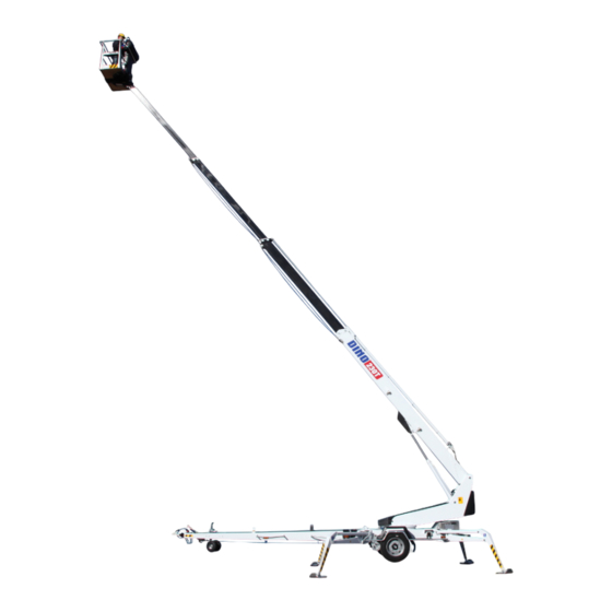
DINO 230T 4 TECHNICAL SPECIFICATION Max. working height 23.0 m Max. platform height 21.0 m Max. outreach 11.7 m Boom rotation continuous Platform rotation 90° Turn area refer to reach diagram Support width 4.40 m Transport width 2.04 m Transport length 8.29 m... -
Page 10: General Description Of The Machine
DINO 230T General description of the machine The denominations of the machine’s essential parts and concepts, which are used later in these instructions, are described on this page. 4.3 Description of the machine’s intended use The Access Platform is exclusively intended for transferring people and tools and acting as a work platform to the limit of its load-bearing capacity and reach (refer to the table of Technical Specifications and Reach Diagram). -
Page 11: General Safety Regulations
DINO 230T 5 GENERAL SAFETY REGULATIONS Make yourself familiar with these operation instructions before using the lift! Keep these operating instructions in the place reserved for them. Make sure that all users of the lift are familiar with these instructions. - Page 12 DINO 230T Do not use ladders, steps or other similar equipment on the platform. Never throw any objects from the platform. The lift must not be used for transferring goods or persons between different floors or working levels. Never disable the operation of any safety device.
-
Page 13: Instructions For Safe Operation
DINO 230T 5.1 !! Instructions for safe operation! Use a safety harness while on the platform. Use hearing protectors when operating the power unit (optional) from the chassis panel. Sound pressure level 92 dB. Never load the platform while in the upper position. -
Page 14: Inspections
DINO 230T Never use a lift alone. Make sure, there is always someone on the ground, who can call for help in case of an emergency. 6 INSPECTIONS A thorough inspection of the lift must be carried out at least once every twelve (12) months. -
Page 15: Worksite Inspection
DINO 230T 7 WORKSITE INSPECTION 1. General information Is the lift suited for the intended job? Is the performance of the lift sufficient for the job? (reach, loadability etc.) Is the position of the lift safe? Is the lighting on the worksite sufficient? 2. - Page 16 DINO 230T...
-
Page 17: Operation Of Safety Devices
DINO 230T 8 OPERATION OF SAFETY DEVICES 1. Support outriggers (Fig. A) The safety limit switch RK3 prevents the operation of the outriggers and the driving device when the boom does not rest on the transport support. The switch is located on the tow-bar at the transport support. - Page 18 DINO 230T...
-
Page 19: Operating Controls
DINO 230T 9 OPERATING CONTROLS 9.1 OPERATING CONTROLS ON THE CHASSIS Selector switch 0 - ignition off 1 - outrigger circuit, hydraulic drive 2 -controlling the boom from the platform panel 3 -controlling the boom from the chassis panel Start button... - Page 20 DINO 230T 18. Signal lights green inside the outreach range at the border of the outreach range 20. Emergency descent device start button 21. Automatic fuse for the platform swing 22. Emergency stop push to stop pull to reset 23. Sound signal 24.
-
Page 21: Operating Controls On The Platform
DINO 230T 9.2 OPERATING CONTROLS ON THE PLATFORM Close the cover of the chassis control panel before operating the platform controls. The cover must not be locked while the lift is in operation. 17. Control lever BOOM BOOM BOOM TO THE LEFT... -
Page 22: Measures To Be Taken In Case Of Emergency/At Risk Of Losing The Stability
DINO 230T MEASURES TO BE TAKEN IN CASE OF EMERGENCY/AT RISK OF LOSING THE STABILITY Reduced stability can be caused by a fault in the lift, the wind or other lateral force, collapse of the standing base or negligence in providing sufficient support. In most cases one sign of reduced stability is the inclination of the lift. -
Page 23: Start-Up
DINO 230T 11 START-UP 1. Ground stability make sure that the ground is even and hard enough to support the lift in a steady level position Soil material Density Max. ground pressure kg/cm² Gravel High density Medium density Loose Sand... - Page 24 DINO 230T 3. Connection of power supply to the lift A. POWERED BY AC-SUPPLY connect the mains cable to the power supply for maximum out of the electric motor the voltage must 230 VAC (-10%/ +6%), the frequency must be 50 Hz and rating of the fuse 16A (the length of the connecting cable has some effect) B.
- Page 25 DINO 230T 4. Check the condition of the battery to ensure operation of the emergency descent system. Keep the emergency descent button depressed for about 5 sec. and ensure that the sound of the reserve power unit does not change noticeably.
- Page 26 DINO 230T...
-
Page 27: Operating The Lift From The Chassis Panel
DINO 230T 11.1 OPERATING THE LIFT FROM THE CHASSIS PANEL 10. Turn the selector switch (1) to position 3 now you are able to operate the boom with levers 7, 8, and 9 on the chassis panel test the operation of the emergency descent system as follows: 1. -
Page 28: Operating The Lift From The Platform Panel
DINO 230T 11.2 OPERATING THE LIFT FROM THE PLATFORM PANEL Note! If you have levelled the chassis of the lift on a GRADIENT, proceed according to the instruction (see point “Operating from the chassis panel”). 11. Turn the selector switch (1) to position 2 and take away the key Do not lock the chassis control panel cover with the key. - Page 29 DINO 230T 12. Test the operation of the outreach limit switch RK4 platform load about 80 kg drive the boom to a horizontal position extend the telescope When the movement stops, the red light (18) must illuminate. compare the outreach with the outreach diagram in this manual (the distance to the outer face of the platform = outreach - 0.5 metres)
- Page 30 DINO 230T The platform movements can be operated with continually adjustable speed from the platform control panel (not from the chassis control panel). DO NOT DAMAGE THE TOW-BAR JOCKEY WHEEL! DO NOT TAKE ADDITIONAL LOAD IN THE UPPER POSITION! NOTE! Lowering the platform to transport position: Always before lowering the boom onto the transport support, retract the telescope completely and turn the platform perpendicular to the boom.
- Page 31 DINO 230T 19. When moving the platform, remember the following be careful of the high voltage power lines do not exceed the max. allowed lateral force (400N) do not touch open electric wires do not throw objects from the platform...
-
Page 32: Emergency Descent System
DINO 230T 12 EMERGENCY DESCENT SYSTEM As a precaution against possible power failure, the lift is equipped with a battery operated emergency descent system. 1. Setup of the system battery 12V 44Ah recharger hydraulic unit 12 VDC 2. Servicing the battery... -
Page 33: Driving Device
DINO 230T 13 DRIVING DEVICE The hydraulic driving device is intended for moving the lift within the work area if the towing vehicle cannot be used. start the generator (internal combustion engine) turn the selector switch 1 for the outriggers to the position 1 (see point “Operating from the chassis panel”) -
Page 34: Special Instructions For Winter Use
DINO 230T As the lift is moved with the driving device, the suitable length for the jockey wheel stem can be achieved by adjusting the gap between the lower surface of the tow-bar/brake rod and the wheel to 1 - 3 cm. -
Page 35: Measures To Be Taken At The End Of The Working Day
DINO 230T 15 MEASURES TO BE TAKEN AT THE END OF THE WORKING DAY 1. Retract the telescope boom completely. 2. Check that the platform is perpendicular to the boom. 3. Lower the boom/platform onto the support on the tow-bar. -
Page 36: Preparing The Lift For Transport
DINO 230T 16 PREPARING THE LIFT FOR TRANSPORT 1. Retract the telescope boom completely. 2. Check that the platform is perpendicular to the boom. 3. Lower the boom/platform onto the support on the tow-bar. the limit switch on the transport support prevents operation of the support outriggers if the platform is not down 4. -
Page 37: Connection To The Towing Vehicle
DINO 230T 17 CONNECTION TO THE TOWING VEHICLE 1. Lift up and push forward the ball-coupling handle (in the driving direction). Now the ball-coupling is released. 2. Press the ball-coupling onto the towball using only a little force. The connection and locking take place automatically. -
Page 38: Instructions For Service And Maintenance
DINO 230T 18 INSTRUCTIONS FOR SERVICE AND MAINTENANCE 18.1 GENERAL SERVICE INSTRUCTIONS carry out the servicing and inspection of the lift in accordance with the instructions when it comes to more demanding repair works turn to a specialist or contact the distributor or... -
Page 39: Service And Inspection Instructions
DINO 230T 18.2 SERVICE AND INSPECTION INSTRUCTIONS 1. The first service after 20 hours of operation change the pressure filter element adjust the brakes according to the instructions (see point "Wheel brakes and bearings") check the the wheel bolts for tightness after about 100 km of driving (325 Nm) 2. -
Page 40: Wheel Brakes And Bearings
DINO 230T 18.3 WHEEL BRAKES AND BEARINGS Adjustment of the brakes Jack up the lift until the wheels rise off the ground and support it in this position. Make sure that the wheels can rotate freely. The brake rods must be slack (with the handbrake released). - Page 41 DINO 230T Adjust the braking force with the nuts keeping the brake balancer perpendicular to the tow-bar so that both wheels will brake. ADJUSTMENT NUTS PERPENDICULAR Tightening the brake system too much causes overheating of the brakes during transportation and increases the required towing force.
- Page 42 DINO 230T Adjustment of the bearing clearance The wheel bearings are lubricated for life and do not require any service. (The bearings do not require any lubrication and they cannot be adjusted) Service intervals 500 km (running in) 5,000 km...
-
Page 43: Lubrication Plan
DINO 230T 18.4 LUBRICATION PLAN... -
Page 44: Long-Term Storage
DINO 230T EVERY 50 HOURS 1. Bearings of the safety device 2. Bearings of the outrigger cylinders 3. Bearings of the outriggers 4. Bearings of the outrigger foot plates 5. Bearings of the boom 6. Bearings of the platform 7. Bearings of the levelling cylinders (except the bearing on the rod side of the upper levelling cylinder) 8. - Page 45 DINO 230T...
-
Page 46: Load Holding And Load Regulation Valves
DINO 230T 18.6 LOAD HOLDING AND LOAD REGULATION VALVES Check of operation 1. To check the tightness of the outrigger cylinder load holding valves measure the height position of the chassis from the floor separately at each outrigger. After a few minutes, measure the height again. -
Page 47: Levelling System Of The Platform
DINO 230T 18.7 LEVELLING SYSTEM OF THE PLATFORM A so-called Slave Cylinder System is applied for levelling of the platform: the slave cylinder under the platform is controlled by a master cylinder the platform keeps its level position only if the valves in the system are tight... -
Page 48: Regular Servicing
DINO 230T 18.8 REGULAR SERVICING The lift shall be serviced regularly at intervals of 11 - 12 month. Under demanding conditions where moist, corrosive substances or corrosive climate may speed up the deterioration of the structure and induce malfunctions, the inspection must be performed more often and the influence of corrosion and malfunctions must be reduced by using appropriate protective means. - Page 49 DINO 230T if required, top up hydraulic oil to the level with the upper edge of the level eye while the lift is in the transport position. 3. Check the hydraulic hoses and pipes Replace any externally damaged hoses or clashed pipes. Check the connections.
- Page 50 DINO 230T 6. Inspection of the boom and the chassis extend the telescope and inspect the platform and its attachment and the boom inspect the boom joints and play of the sliding pads, readjust if necessary. Lubricate the sliding surfaces...
- Page 51 DINO 230T 7. Check the overrun attachment of the overrun clearance condition of the towball-coupling condition of the locking device check that the overrun brake mechanism moves freely: stop the lift, as instructed (see point "Preparing the lift for transport")
- Page 52 DINO 230T 10. Operation of the safety devices while they are controlled from the chassis control panel lift the platform slightly up from the transport position the outriggers must not operate in any position of the selector switch lift the boom and test the following: 1.
-
Page 53: Testing The Outreach Limit Switch
DINO 230T 18.8.2 TESTING THE OUTREACH LIMIT SWITCH Put a carefully weighed load (80 kg) on the platform. Place it at a distance of 100 mm from the rear edge of the platform. Extend the telescope until it stops. Measure the length of the protruding part of the telescope extension(L). The length shall be 2,050 mm ±50 mm. -
Page 54: Testing The Overload Limit Switches
DINO 230T 18.8.3 TESTING THE OVERLOAD LIMIT SWITCHES the second safety limit switch (RK5) backs up if the first switch outreach limit switch (RK4) fails disable the RK4 for testing by disconnecting the conductor 40 and connecting the conductors 13 and 39 in the chassis... -
Page 55: Setting Of The Outreach Limit Switch And The Overload Limit Switch
DINO 230T 18.8.4 SETTING OF THE OUTREACH LIMIT SWITCH AND THE OVERLOAD LIMIT SWITCH Always check the operation of both limit switches in connection with the service. put a load of 80 kg onto the platform drive the boom to a horizontal position... - Page 56 DINO 230T Adjustment method I: make sure that the RK5 with certainty will trip before the RK4 by adjusting the RK4 extend the boom and measure the length of one protruding part of the telescope extension (stroke) the measure shall be 2,350 mm ±50 mm.
- Page 57 DINO 230T 11. Measuring the pressure connect the pressure gauge to the measuring point the max. pressure with warm (40 - 60 °C) oil is 20 -20,5 MPa (200 -205 bar) the turning pressure is 6 MPa (60 bar) if you have to readjust the pressure, secure the new setting with a seal 12.
-
Page 58: Inspection Instructions
DINO 230T 14. Inspect the brakes and the driving device remove the wheels clean the brake system and check the settings check the free movement of the brake shoes the operation of their return springs replace any worn out linings... -
Page 59: Sample Of Inspection Protocol For The Access Platform
DINO 230T 19.1.1 SAMPLE OF INSPECTION PROTOCOL FOR THE ACCESS PLATFORM... - Page 60 DINO 230T...
-
Page 61: Daily Inspection (Start-Up Inspection)
DINO 230T 19.2 DAILY INSPECTION (START-UP INSPECTION) To be always performed at a new work site and in the beginning of every working day. The inspection is performed by the user. In the inspection attention shall be paid to the following issues: establish the load-bearing capacity of the ground at the lifting site (see the normative table "Maximum permissible ground pressure for different soil materials"... -
Page 62: Monthly Inspection (Maintenance Inspection)
DINO 230T 19.3 MONTHLY INSPECTION (MAINTENANCE INSPECTION) The inspection shall be performed by a person who is well familiar with the lift. Task list for inspection: perform the measures of the daily inspection check the attachment points of the boom and the platform... -
Page 63: Annual Inspection (Regular Inspection)
DINO 230T 19.4 ANNUAL INSPECTION (REGULAR INSPECTION) The inspection shall be performed by a skilled technician or an expert inspection body with documented evidence of competence (see point “Inspections”). In the inspection special attention has to be paid to the condition of the steel structures, the safety devices and the operating system. - Page 64 DINO 230T directional valves on the chassis check that the valves of the support outriggers and the driving device work properly and no movements are executed when the spools are in the neutral position electro-hydraulic rotary adaptor check the adaptor for tightness...
- Page 65 DINO 230T check the condition of the boom joint check the bearing and the pin of the boom joint and the locking of the pin check the condition and attachment of the articulated arm joint pins and bearings check the support outriggers and their footplates...
-
Page 66: Extraordinary Inspection
DINO 230T check the condition of the chassis general condition check the attachment of the tow-bar to the chassis check the condition of the overrun and its attachment to the chassis. check the axle and its attachment to the chassis... -
Page 67: Test Loading Instructions For Regular Inspection
DINO 230T 19.6 TEST LOADING INSTRUCTIONS FOR REGULAR INSPECTION 1. Place the lift on an even surface with good carrying capacity. Drive the outriggers to their lowest position (the minimum support width). 2. Turn the boom to the side from the tow-bar and lower it on the ground. -
Page 68: Fault Finding
DINO 230T FAULT FINDING FAULT REMEDY 1. Electric motor does not start although the start button is pressed and the selector switch is in position 1, 2 or 3 Emergency stop button is stuck. Pull up the button and re-start the engine with the start button. - Page 69 DINO 230T FAULT REMEDY 4. Disturbance of platform movements - only one of the movements is operational Irregular and indefinite malfunctions. Make sure that the hydraulic oil and the filter have been changed. Thoroughly clean the solenoid valve spools and housings (requires utmost cleanliness - not all contaminants can be spotted with the naked eye).
- Page 70 DINO 230T FAULT REMEDY 8. Boom cannot be lifted Refer to item 4. The solenoid valve is in the neutral or in the lowering position. Remedy as instructed above in conjunction with the seizure of the electric valve spool. The lift turns as the lifting movement is Solenoid valve is stuck in turning position.
- Page 71 DINO 230T FAULT REMEDY 12. Platform drifts forward Double load regulation valve on the rod side is Measures as above. leaking. 13. Outriggers do not move though the selector switch is in position 1 Boom does not rest on the transport support.
- Page 72 DINO 230T FAULT REMEDY 17. Too low braking force Too much play in the brake system. Adjust the brake system (see point "Wheel brakes and bearings"). Brake linings not yet run-in. Pull the parking brake lever slightly and drive 2 - 3 kilometres.
- Page 73 DINO 230T FAULT REMEDY 23. Ball-coupling is not locked Inner parts of the ball-coupling dirty. Clean and lubricate. Tow-ball of the towing vehicle too large. Measure the tow-ball. According to DIN74058 the diameter of the ball must be max. 50 mm and min.
-
Page 74: Operation Of Electric Components
DINO 230T 21 OPERATION OF ELECTRIC COMPONENTS 21.1 MAIN CENTRE (PK), RELAYS K1: START CONTACTOR (M1) FOR THE ENGINE K2: AUXILIARY RELAY FOR EMERGENCY STOP BUTTON Switches off the mains supply (230VAC). K3: AUXILIARY RELAY FOR SWITCHING OFF THE "BOOM DOWN" MOVEMENT The limit switch RK4 controls the relay (delay 0,6 seconds). - Page 75 DINO 230T K23: CONTROL RELAY OF THE SELECTOR VALVE ON THE CHASSIS The relay closes as the control movements from the chassis panel are actuated. K24: CONTROL RELAY FOR MOVEMENT SPEED OF THE BOOM Connecting relay for retardation resistors which are actuated by the stroke of the telescope...
-
Page 76: Main Centre (Pk), Switches
DINO 230T 21.2 MAIN CENTRE (PK), SWITCHES S1: LOCKING EMERGENCY STOP SWITCH Stops all other functions except the emergency descent and the sound signal, which remain operational. S2: START SWITCH Non-locking button switch. S3: STOP SWITCH Non-locking button switch. S13: START SWITCH OF THE EMERGENCY DESCENT SYSTEM Non-locking button switch. - Page 77 DINO 230T Notes...
-
Page 78: Platform Control Panel (Ok), Relays
DINO 230T 21.3 PLATFORM CONTROL PANEL (OK), RELAYS K13: CONTROL RELAY FOR SIGNAL LIGHTS WHICH INDICATE THE STATE OF LOADING OF THE PLATFORM Relettä ohjaa turvaraja RK4. K14 AND K15: CONTROL RELAYS FOR TURNING THE PLATFORM (TO THE RIGHT- TO THE LEFT) The relays are controlled by inductive limit switches RK9 and RK10 of the linear actuator (M3). -
Page 79: Platform Control Centre (Ok), Switches
DINO 230T 21.4 PLATFORM CONTROL CENTRE (OK), SWITCHES DMK: DEAD-MAN-SWITCH JST: JOYSTICK The left-hand side of the rocker switch depressed (movements are: boom up - down and turn right – left). The right-hand side of the rocker switch depressed (the movements are: telescope out – in). -
Page 80: Limit Switches
DINO 230T 21.5 LIMIT SWITCHES RK3: LIMIT SWITCH FOR THE BOOM SUPPORT Prevents the operation of the outriggers and the driving device if the boom does not rest on the support in the transport position. Controls the relay K30. RK4: SAFETY LIMIT SWITCH FOR THE ADJUSTED OPERATING RANGE RK5: BACKUP LIMIT SWITCH FOR THE SAFETY LIMIT SWITCH RK4. -
Page 81: Control Box Of The Driving Device
DINO 230T 21.6 CONTROL BOX OF THE DRIVING DEVICE S24: DRIVING STRAIGHT, FORWARD AND BACKWARD Non-locking lever switch. S25: TURNING TO THE LEFT Non-locking button switch. S26: TURNING TO THE RIGHT Non-locking button switch. 21.7 REMOTE CONTROL BOX OF THE DRIVING DEVICE S24B: DRIVING STRAIGHT, FORWARD AND BACKWARD Non-locking lever switch. -
Page 82: Other Markings
DINO 230T 21.9 OTHER MARKINGS B1: BATTERY FOR EMERGENCY DESCENT MOTOR 12VDC 44AH B2: STARTING BATTERY OF THE GENERATOR 12VDC 45AH E1: THERMO-RELAY (M1) FOR THE ENGINE F1: FUSE FOR POWER SUPPLY TO STARTING DEVICE (10A) F2: CONTROL FUSE FOR THE DRIVING DEVICE AND THE SUPPORT OUTRIGGERS (10A) - Page 83 DINO 230T M3: MOTOR FOR PLATFORM TURN Q1: SELECTOR SWITCH FOR CONTROL PLACE I = support outriggers, II = controls on the platform and III = controls on the chassis. SR1: SOLENOID OF THE EMERGENCY DESCENT UNIT SR4: STARTER SOLENOID OF THE GENERATOR...
-
Page 84: Adjustment Values Of Movement Speeds
DINO 230T 22 ADJUSTMENT VALUES OF MOVEMENT SPEEDS 1. Measuring devices required for the adjustment volt-ohm-milliammeter measuring adapter (for measuring of current) 2. Disconnect the socket from the Propo-valve and connect the measuring adapter between the valve and the Propo-card 3. - Page 85 DINO 230T 7.1. The power unit does not have to be running. Operate the "boom up" movement from the platform panel and adjust I = ~1,350mA with the screw 1 on the Propo-card. 8. The movement speeds are adjusted with the adjustable resistors in the main control centre.
- Page 86 DINO 230T 12.1. The power unit does not have to be running, key-switch in position 3. Measure the Propo- valve current while operating the platform levelling and adjust the current value to ~650mA using the potentiometer TR5 on the main centre cover.
-
Page 87: Electric Components 23037
DINO 230T 23 ELECTRIC COMPONENTS 23037 > REF. PART NR. DESCRIPTION 48.2276 BATTERY BATTERY 48.2315 THERMAL RELAY F1, F2, F3, F5 48.647 10A FUSE F4, F7 48.3030 1.6A FUSE 48.3036 + 48.1034 AUTOMATIC FUSE 48.3395 LEAD PROTECTOR 230V 10A LEAD PROTECTOR 230V 16A GENERATOR 48.2204... - Page 88 DINO 230T BATTERY CHARGER, 48.0125 AUTOMATIC TR1-TR5 48.2269 RESISTOR 48.2436 VOLT METER FAULT CURRENT SAFETY 48.2128 SWITCH ÄM1 48.049 SIGNAL HORN ÄM2 48.0108 SIGNAL HORN...
-
Page 89: Electric Diagram 23037
DINO 230T 24 ELECTRIC DIAGRAM 23037 ->... - Page 90 DINO 230T...
- Page 91 DINO 230T...
- Page 92 DINO 230T...
-
Page 93: Electric Diagram, (Diesel Generator) 23017
DINO 230T... -
Page 94: Electric Diagram, (Diesel Generator) 23017
DINO 230T... -
Page 95: Electric Diagram, (Diesel Generator) 23017
DINO 230T... -
Page 96: Electric Diagram, (Diesel Generator) 23017
DINO 230T... -
Page 97: Electric Diagram, (Diesel Generator) 23017
DINO 230T... -
Page 98: Electric Diagram, (Diesel Generator) 23017
DINO 230T... -
Page 99: Electric Diagram, (Diesel Generator) 23017
DINO 230T... -
Page 100: Electric Diagram, (Diesel Generator) 23017
DINO 230T... -
Page 101: Electric Diagram, (Diesel Generator) 23017
DINO 230T ELECTRIC DIAGRAM, (DIESEL GENERATOR) 23017 ... -
Page 102: Hydraulic Components 23039
DINO 230T 26 HYDRAULIC COMPONENTS 23039 > Ref. Part nr. Item Pcs. 47.828 Electric motor 47.2068 Hydraulic pump 47.195 Pressure filter 47.2803 Pressure relief valve 47.2824 3/2 Solenoid valve 47.2713 Solenoid valve 47.2630 Solenoid valve 47.378 Solenoid valve 47.2749 Double pressure limiting valve 47.2750... -
Page 103: Hydraulic Diagram
DINO 230T 27 HYDRAULIC DIAGRAM 23001 >... - Page 104 DINO 230T Notes...
Need help?
Do you have a question about the 230T and is the answer not in the manual?
Questions and answers