
Subscribe to Our Youtube Channel
Related Manuals for Xylem Bell & Gossett Hoffman Speciality Series


Summary of Contents for Xylem Bell & Gossett Hoffman Speciality Series
- Page 1 • Application • Selection • Installation • Piping Diagrams Hoffman Specialty ® Steam Traps ENGINEERING DATA MANUAL HS-203C...
-
Page 2: Table Of Contents
Contents Introduction Steam Trap Functional Requirements Operation, Advantages, Disadvantages and Primary Applications Chapter 1 Selection Guide Chart 4-Step Method for Sizing Helpful Hints, Formulas and Conversion Factors Properties of Saturated Steam Steam Flow in Pipes Condensation in Pipes Chapter 2 Flash Steam Explanation and Calculation Operating Pressure Limits Installation and Calculating Differential Pressure 18... -
Page 3: Introduction
Introduction Steam Trap There are many types of steam traps each Water Hammer having its unique characteristics and system When a trap drains high temperature conden- Functional benefits. Hoffman Specialty offers thermostat- sate into a wet return, flashing may occur. ic, thermodisc, float and thermostatic, and Requirements When the high temperature condensate at... -
Page 4: Operation, Advantages, Disadvantages And Primary Applications
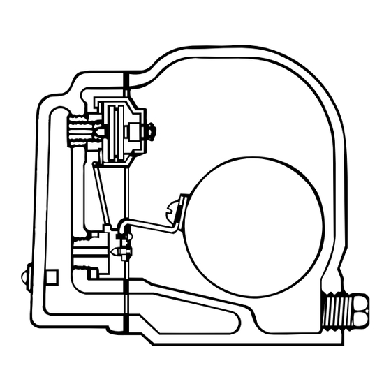
TRAP OPERATION Operation, Advantages, A review of the trap operating principle will show how various types of traps meet the dif- Disadvantages, ferent system characteristics. and Primary Float & Thermostatic Traps Applications Primary Applications Advantages Heating main drip traps. Completely drains condensate at satura- tion temperature. - Page 5 Bucket Traps Advantages Primary Applications Completely drains condensate at saturation Process main drip traps. temperature. Where condensate is lifted or drains into wet Open bucket will tolerate moderate return line. water hammer. Drum type roller dryers. Available in pressures up to 250 psig. Steam separators.
- Page 6 Thermostatic Bellows Type Trap Advantages Applications Sub-cools condensate usually 10° to 30°F. Radiators, convectors, unit heaters. Normally open at start-up to provide fast Cooking kettles. air venting. Sterilizers. Follows steam saturation curve to operate Heating coils. over wide range of conditions. Tracer lines.
- Page 7 Disc Traps Advantages Applications Completely drains condensate at satura- Steam tracer lines where maximum tem- tion temperature. perature is required. May be installed vertically, to drain trap Outdoor applications including drips on body when steam is off, to prevent freezing. steam mains.
- Page 8 Disc Trap Operation Operating Start-Up As the condensate nears saturation tempera- The disc is pushed off the seat by the inlet ture, greater amounts of flash steam will pressure and is held open by the impact force appear. Some of the flash steam escapes to of the condensate hitting the disc.
-
Page 9: Selection Guide Chart
Chapter 1 Selection The proper type of steam trap selected is an and disc traps. This line chart points out sys- important consideration in steam systems. tem conditions that may be encountered and Guide Chart There are many types of steam traps. Each suggests a trap that may best handle the has unique characteristics and system bene- requirement. -
Page 10: 4-Step Method For Sizing
Step 1: Step 3: 4 Step Method Collect All Required Information. Apply Safety Factor. for Sizing A. Determine maximum condensate load in A. SFA Recommended. Lbs./Hr. (Pounds per Hour). See “Helpful 1. Float & Thermostatic Trap 1.5 to 2.5. Hints—Approximating Condensate Loads” 2. -
Page 11: Helpful Hints, Formulas And Conversion Factors
Helpful Hints, Helpful Hints 3. Steam heats a solid or slurry indirectly through a metallic wall. Formulas and Approximating Condensate Loads —Clothing press, cylinder driers, platen Heating Water with Steam Conversion —press. lbs./hr. Condensate = GPM Factors Lbs./hr. condensate = x Temperature Rise °F. -
Page 12: Properties Of Saturated Steam
The Properties of Saturated Steam table Latent Heat: Properties of provides the relationship of temperature and The amount of heat expressed in Btu required Saturated pressure. The table also provides Btu heat to change 1 Ib. of water at saturation temper- values of steam and condensate at various Steam ature into 1 Ib. - Page 13 Properties of Saturated Steam BELOW ATMOSPHERIC PRESSURE ABOVE ATMOSPHERIC PRESSURE (Cont.) Heat Content Heat Content Specfic Latent Specfic Latent Btu per Ib. Btu per Ib. Vacuum Saturated Volume Heat of Pressure Saturated Volume Heat of Inches of Temp Cu. ft. Saturated Saturated Vaporization Temp Cu.
-
Page 14: Steam Flow In Pipes
Steam Flow in Pipes REASONABLE VELOCITIES for fluid flow through pipes Fluid Pressure PSI (Gauge) Service Velocities—FPM SATURATED STEAM 0-15 Heating Mains 4000-6000 SATURATED STEAM 50-up Miscellaneous 6000-8000 SUPERHEATED STEAM 200-up Turbine and Boiler Leads 10000-15000 WATER 25-40 City Service 120-300 WATER 50-150... -
Page 15: Flash Steam Explanation And Calculation
Flash Steam Flash Steam From Properties of Saturated Steam Table: When hot condensate above the saturation Explanation F. ____Btu/Lb. in Condensate at Initial temperature under pressure, is released to ____Pressure. atmospheric pressure, the excess heat is given off by reevaporation or what is common- G. -
Page 16: Operating Pressure Limits
Steam Trap Operating Pressure Selection Operating Excessive Steam Pressure A given size float and thermostatic trap or Pressure Forces Trap Closed bucket trap is offered with various orifice Limits sizes which determine the maximum pressure rating. A Hoffman Specialty F & T trap for example is offered with seats rated 15 psi, 30 psi, 75 psi, 125 psi and 175 psi. -
Page 17: Installation And Calculating Differential Pressure
Installation Trap Installation Piping Details Steam traps should be installed in an acces- A dirt pocket should be provided ahead of the sible location at least 15 inches below the steam trap to collect scale and dirt. A shut-off Calculating condensate outlet of equipment or steam valve should be provided ahead of the trap to mains being drained. - Page 18 The use of bypass piping around steam traps Differential Pressure is not recommended. Bypass valves, if The differential pressure across the trap will opened, may cause pressurization of conden- be the sum of the minimum operating pres- sate receivers and cause a safety hazard. sure, plus the positive static head at the trap Where stand-by protection is desired the use inlet minus any back-pressure in the return...
-
Page 19: Drip Traps For Distribution Pipes
Drip Traps for Drip Traps for Steam Distribution Piping In systems using automatic start-up the steam boiler is used to bring the mains up The steam distribution piping, often referred Distribution to final pressure and temperature without to as steam mains, provides the link between supervision. - Page 20 Calculation of the running load is figured Calculation for warm-up load at start-up: using the following formula: Warm-up load Ib./hr. = Ibs./hr. running load heat loss = W x(T )x.114 L L x U x ∆T x E W = Weight of pipe (see table below for S x H weight per ft.).
- Page 21 Example: Assume a steam supply header to The final sizing for our example would be to feed tracer lines is 11/4” pipe size operating size the trap for 236 x 2 = 472 Ibs./hr. con- at 30 psig and is 800 ft. Iong, insulated 75% densate based on the differential pressure effect, minimum ambient at start-up is 10°F.
- Page 22 Installation of drip trap ahead of riser or expansion joint TRAP STATIC HEAD SHUT-OFF SHUT-OFF VALVE VALVE “Y” STRAINER Installation of drip trap in long run of steam piping or ahead of control valves STATIC TRAP HEAD SHUT-OFF SHUT-OFF VALVE VALVE “Y”...
-
Page 23: Selecting Traps For Heat Exchangers
Chapter 3 Selecting Steam heating devices using a modulating Complete condensate drainage under all vary- temperature regulator must operate over a ing pressure and condensing loads is essen- Steam Traps wide range of conditions. As the temperature tial to prevent tube damage due to water regulator controls the flow of steam, condesa- hammer. - Page 24 modulate over a wide range of conditions, pro- Guidelines for selecting traps for heat viding a drainage rate equal to the system exchangers using modulating steam tempera- load. The Float and Thermostatic Trap also ture regulators are as follows: has a separate thermostatic vent to provide —Select capacity based on maximum con- quick passage of air during start-up or during densing load at minimum differential pressure...
- Page 25 Condensate Coolers When a modulating steam regulator is used on the steam-to-water heat exchanger, the When heat exchangers are selected for opera- vacuum breaker will allow air to enter to pre- tion above 2 psig, consideration should be vent an induced vacuum from holding up con- given to the addition of a condensate cooler.
-
Page 26: Lock-Out Traps For Start-Up Loads
Lock-out Traps For Draining Condensate Lock-out Trap Used to Drain Lock-Out Under Low Pressure. Underground Steam Main. Traps for In the discussion of trap operation, we point- One application of a lock-out trap is to drain Start-Up ed out that if the differential pressure across condensate from underground steam lines Loads the trap seat exceeds the trap pressure rat-... -
Page 27: Draining Condensate To Overhead Returns
Draining Draining Condensate to Overhead Returns or into Pressurized Return Lines Condensate to When a positive pressure is assured across Overhead the steam trap, 1 psi will raise condensate 2 feet. When a positive pressure is not Returns assured, such as the case when using a steam control valve, provision must be made to drain condensate at reduced pressure loads and during initial start-up. -
Page 28: Draining Submerged Coils
Submerged Pipe Coils tube is placed inside the large tube and Draining insures that steam will not enter the trap until Submerged pipe coils are sometimes gravity Submerged all of the condensate has been drained from drained, with the trap installed below the coil. Coils the coil. -
Page 29: Jacketed Kettles
Jacketed Jacketed Kettles Air Handling Capability Kettles are often of the tilting type. These The excellent air handling capability of Kettles require the use of a siphon drain. Siphon Thermostatic Traps makes them suitable for drains may either be internal or external. The trapping applications where quick air removal Fig. -
Page 30: Cylinder Dryers
Cylinder Dryers Cylinder Cylinder dryers are widely used in the process- Because of their large volume and surface Dryers, Unit area, traps for this type of application should ing industry. Since they are usually rotating in Heaters be sized with a substantial safety factor. This nature, siphon drainage of the condensate is involved. -
Page 31: Steam Radiators
Steam Radiators Trap Damage from Water Hammer Radiators normally use Thermostatic Traps to When automatic temperature controlled sup- Radiators drain condensate. The Thermostatic Trap is a ply valves are used, water hammer may occur pressure balanced device that will open usual- when the valve closes. -
Page 32: Typical Piping For Steam Heating
The piping and radiator connections shown in this section are Typical Piping diagrammatic and illustrate the proper method of making piping for Steam connections. They are not dimensional and cannot be scaled for Heating pipe size or product size. Two pipe steam systems radiator connections Radiator connections Dripping heel of DOWN FEED RISERS... - Page 33 Piping connections for unit heaters (steam) SUPPLY LINE SUPPLY LINE UNIT HEATER UNIT HEATER UNIT HEATER VENT VALVE AT LEAST 12" RETURN SEDIMENT POCKET STRAINER SEDIMENT POCKET CHECK VALVE Vacuum or low pressure open Low pressure closed gravity system gravity system GATE VALVE SUPPLY LINE SUPPLY MAIN...
- Page 34 Two pipe– steam trap installations SUPPLY MAIN SUPPLY RISER RETURN RISER MINIMUM COOLING LEG 5'0" LONG SAME SIZE AS TRAP HORIZONTAL BRANCH PIPES TRAP 45° ELBOWS DRY RETURN DRY RETURN MAIN Dripping end of supply main into dry return SUPPLY MAIN Connections for upfeed risers DROP RISER OR END OF MAIN...
- Page 35 One pipe steam systems radiator connections SUPPLY MAIN PACKLESS PACKLESS RADIATOR RADIATOR AIR VALVE VALVE VALVE PITCH DOWN FROM HERE SUPPLY MAIN VENT VALVE Upfeed connection to radiator NOT LESS THAN 18" REDUCER WATER LINE OF BOILER CAN BE REDUCED (Never Less than 3/4 ") PACKLESS...
- Page 36 STEAM MAIN AT LEAST 24" MAIN VENT DRY BLEEDER AT LEAST 12" AT LEAST 18" ABOVE W.L. DIRT POCKET RETURN Dripping end of one pipe steam main where same extends beyond wet return Expansion joint made up of pipe for horizontal pipes–dripped into wet return Expansion joint made up of pipe for horizontal pipes–not dripped...
- Page 37 NOTE: RISER Indicates direction of pitch RADIATOR BRANCH in piping connections RISER Upfeed branch connection taken from main at 45° Method of taking double radiator branch connections from riser 45° ECCENTRIC REDUCER ACCEPTABLE PREFERRED Method of taking branches from mains Method of reducing size of mains RISER Drop riser branch taken...
-
Page 38: Trapping Steam Tracer Lines
Each individual steam tracer line requires a Trapping separate trap to assure condensate drainage. Steam Tracer When more than one tracer line is manifolded Lines into a common trap, condensate can back up in the line with the greatest pressure drop. Individual tracer line trap selection guide: 1. -
Page 39: 4-Step Method For Sizing Steam Lines
Chapter 4 4-Step Method for Sizing Steam Lines Based on Moody Friction Factor where flow of condensate does not inhibit the flow of steam. Basic Chart for Weight-Flow Rate and Velocity of Steam in Schedule 40 Pipe Based on Saturation Pressure of 0 PSIG Figure 10 Reprinted by permission from ASHRAE 1972 Handbook of Fundamentals... - Page 40 Velocity of Steam Step 3 General Heating Applications— Try 3 inch pipe showing 10,000 fpm velocity 4,000 to 6,000 fpm. and pressure drop of approximately .9 psi Process Pipe— per 100 feet. 6,000 to 12,000 fpm. Step 4 Sample Problem Using Steam Velocity Use velocity multiplier chart.
-
Page 41: 4-Step Method For Sizing Return Lines
ASHRAE Condensate that collects ahead of a steam based on the steam operating pressure and trap is approximately at saturation the allowable p/L, psi/100 ft. Selections for Method for temperature and corresponds to the 100 and 150 psig steam for either a vented operating pressure. -
Page 42: Testing Steam Traps
Chapter 5 Where a test valve is installed in the trap dis- ball should seat. If the trap is blowing live Testing Steam charge piping, visual inspection is the most steam the ball will move inside the housing. Traps positive method of testing. Many independent trap survey companies will Thermostatic Traps, and F &... - Page 43 Trap Type is a Factor Thermostatic Float & Thermostatic • Modulates • Modulating device. • Discharges continuously. • Element passes air. • Sound test—rush of condensate, hiss of live steam. • More intense—for failed element passing • steam. • Visual—must distinguish between flash & live steam. •...
- Page 44 Disc • Best test is sound. • Trap cycling is audible. • Disc slams against seat. • Leaking seat—would be heard. • Rapid cycle—excessive wear. Bucket Trap • Machine gunning—live steam. • Discharges full capacity then shuts off. • Muffled rattle of bucket on outer chamber. •...
-
Page 45: Definition Of Heating Terms
Chapter 6 Definition of The definitions given in this section are only Atmospheric Pressure: The weight of a column those applying to heating and particularly as of air, one square inch in cross section and Heating Terms used in this book. Some do not define the terms extending from the earth to the upper level of for all usages. - Page 46 Coefficient of Heat Transmission (Over-all)-U-: Cooling Leg: A length of uninsulated pipe The amount of heat (Btu) transmitted from air to through which the condensate flows to a trap air in one hour per square foot of the wall, floor, and which has sufficient cooling surface to per- roof, or ceiling for a difference in temperature of mit the condensate to dissipate enough heat to...
- Page 47 Fahrenheit: A thermometer scale at which the Horsepower: A unit to indicate the time rate of freezing point of water is 32° and its boiling doing work equal to 550 ft.-lb. per second, or point is 212° above zero. 33,000 ft.-lb. per minute. One horsepower equals 2545 Btu per hour or 746 watts.
- Page 48 Pressure: Force per unit area such as Ib. per sq. Square Foot of Heating Surface: Equivalent inch. Unless otherwise qualified, it refers to unit direct radiation (EDR). By definition, that amount static gauge pressure. See Static, Velocity, Total of heating surface which will give off 240 Btu per Gauge and Absolute Pressures.
- Page 49 Total Heat: The latent heat of vaporization Warm Air Heating System: A warm air heating added to the heat of the liquid with which it is in plant consists of a heating unit (fuel-burning fur- contact. nace) enclosed in a casing, from which the heat- ed air is distributed to the various rooms of the Total Pressure: The sum of the static and veloci- building through ducts.
- Page 50 Xylem, Inc. 8200 N. Austin Avenue Morton Grove, Illinois 60053 Phone: (847) 966-3700 Fax: (847) 965-8379 www.xyleminc.com/brands/bellgossett Bell & Gossett is a trademark of Xylem, Inc. or one of its subsidiaries. © 2012 Xylem, Inc. HS-203CA April 2000...
Need help?
Do you have a question about the Bell & Gossett Hoffman Speciality Series and is the answer not in the manual?
Questions and answers