Table of Contents
Advertisement
Quick Links
Advertisement
Table of Contents

Related Manuals for Xylem Sanitaire Silver Series


Summary of Contents for Xylem Sanitaire Silver Series
- Page 1 Installation, Operation, and Maintenance Manual Sanitaire, Silver Series...
-
Page 3: Table Of Contents
Table of Contents Table of Contents 1 Introduction and Safety......................3 1.1 Introduction.......................... 3 1.2 Safety terminology and symbols..................3 1.3 User safety..........................4 1.4 Special hazards........................4 1.5 Protecting the environment....................6 1.6 Spare parts..........................6 1.7 Warranty..........................6 2 Transportation and Storage...................... 7 2.1 Inspect the delivery......................7 2.1.1 Inspect the package..................... - Page 4 Table of Contents 5 Operation..........................35 5.1 Precautions......................... 35 5.2 Start the system........................35 6 Maintenance..........................38 6.1 Precautions......................... 38 6.2 Preventive maintenance....................38 6.2.1 Moisture purging......................38 6.2.2 Air bumping........................ 39 6.2.3 Power failure and loss of air supply................39 6.2.4 Visual inspection......................39 6.3 Recurrent maintenance.....................
-
Page 5: Introduction And Safety
This includes any modification to the equipment or use of parts not provided by Xylem. If there is a question regarding the intended use of the equipment, please contact a Xylem representative before proceeding. -
Page 6: User Safety
1 Introduction and Safety Special symbols Some hazard categories have specific symbols, as shown in the following table. Electrical hazard Magnetic fields hazard Electrical Hazard: CAUTION: 1.3 User safety All regulations, codes, and health and safety directives must be observed. The site •... - Page 7 1 Introduction and Safety them vulnerable to drowning if they fall face down into a small pool of water. Never work alone where there is a risk of drowning. Working with solvents WARNING: Explosion/Fire Hazard Before starting any permit-required hot work such as welding, gas cutting, grinding, or using electrical handtools, do the following: 1.
-
Page 8: Protecting The Environment
• Clean-up of spills Exceptional sites CAUTION: Radiation Hazard Do NOT send the product to Xylem if it has been exposed to nuclear radiation, unless Xylem has been informed and appropriate actions have been agreed upon. 1.6 Spare parts CAUTION: Only use the manufacturer’s original spare parts to replace any worn or faulty... -
Page 9: Transportation And Storage
2 Transportation and Storage 2 Transportation and Storage 2.1 Inspect the delivery 2.1.1 Inspect the package 1. Inspect the package for damaged or missing items upon delivery. 2. Note any damaged or missing items on the receipt and freight bill. 3. -
Page 10: Storage Guidelines
2 Transportation and Storage 1. Lifting point 2. Minimum 2 m (6 ft 7 in.) 3. Lifting device Figure 1: Lifting points 1. Check that the site where the equipment components will be placed has a clean and level surface. 2. -
Page 11: Specific Storage Requirements
2 Transportation and Storage NOTICE: Do not stack shipping units. NOTICE: Do not place heavy weights on the packed product. NOTICE: Protect the product against humidity, heat sources, and mechanical damage. NOTICE: Risk of wear. Make sure the equipment is clean before it is placed into service. 2.3.2 Specific storage requirements Component Storage... -
Page 12: System Description
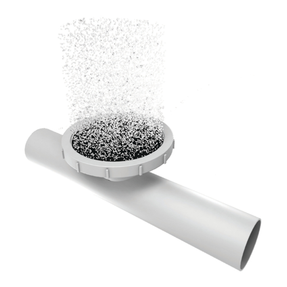
3 System Description 3 System Description Diffusers included Type Model Fine bubble Silver Series II LP, 7 and 9 in. Silver Series II, 7 and 9 in. 3.1 Diffuser design Fine bubble disc diffusers are designed for an efficient and reliable aeration and mixing process of industrial and municipal wastewater. -
Page 13: Installation
4 Installation 4 Installation 4.1 Precautions Before starting work, make sure that the safety instructions in the chapter Introduction and Safety (page 3) have been read and understood. Requirements The following requirements apply: • Never work alone. • Make sure to have a clear path of retreat. •... -
Page 14: Dropleg And Manifold Installation
4 Installation Figure 3: Support with strut, low Figure 4: Support with strut, high 4.3 Dropleg and manifold installation Prerequisites • Always use the highest point of the tank floor as a reference when leveling. • Ensure that the air filtration equipment is installed and operating. •... -
Page 15: Lay Out The Manifold Centerline
4 Installation Installation procedure overview The manifold installation includes the following steps: • Lay out the manifold centerline (page 13) • Lay out the manifold support locations (page 14) • Install the manifold anchors and supports (page 15) • Assemble the manifold pipe sections (page 17) •... -
Page 16: Lay Out The Manifold Support Locations
4 Installation 1. In-line manifold 2. Offset manifold 1. Locate the centerline of the manifold. Use the installed upper dropleg and the installation drawings. 2. Mark clearly the position on the floor. 4.3.2 Lay out the manifold support locations 1. Locate and layout all manifold support locations. Sanitaire, Silver Series Installation, Operation, and Maintenance Manual... -
Page 17: Install The Manifold Anchors And Supports
4 Installation Use the installation drawings and shippings lists. 2. Mark clearly the positions on the floor. 4.3.3 Install the manifold anchors and supports The manifold sections must be placed according to the manifold and anchor layout before the anchors are installed. Always use the highest point of the tank floor as a reference when leveling. - Page 18 4 Installation The tightening torque values are listed in the installation instructions from the anchor bolt manufacturer. 5. On a single anchor support, install the locating plate with the two bent prongs in front, inside the support rod, and the single prong to the back, inside the u-bend. Install all supports in the same direction.
-
Page 19: Assemble The Manifold Pipe Sections
4 Installation 1. Hexagon nut Project-specific anchor dimensions are found in the erection drawing. 2. Strut 3. Anchor bolt 4. Clamp 5. Washer 6. Hexagon nut 7. Rod 8. Anchor bolt 9. Hexagon nut 10.Washer, round 11.Washer, square 8. Use the installation drawings and a level system to find the correct clamp flange elevation. - Page 20 4 Installation 4. Connect the manifolds: a) Connect flanges with bolts loosely. b) Connect joints with glue. c) Connect spline couplings without tightening. 5. Install the upper part of the support clamp with washers and nuts. Tighten loosely. 6. Level the manifold sections which attach to the droplegs. –...
-
Page 21: Install The Lower Dropleg
4 Installation Do not secure the clamps on these sections at this point. 9. Install the lower dropleg according to Install the lower dropleg (page 19). 10.Complete the manifold installation: a) Level the remaining manifold sections and ensure that the air distributor connections are level. - Page 22 4 Installation Figure 10: Upper and lower dropleg 7. Install the clamp coupling or tighten the flange connection. Tighten the clamp coupling bolts to a torque of 70–75 Nm (50–55 ft-lbs). Figure 12: Example of flange connection Figure 11: Example of clamp coupling 8.
-
Page 23: Air Distributor Installation
4 Installation 4.4 Air distributor installation Installation procedure overview The installation includes the following steps: • Lay out the air distributor support locations (page 21) • Install the air distributor anchors and supports (page 22) • Assemble an air distributor section (page 23) –... -
Page 24: Install The Air Distributor Anchors And Supports
4. Make the required adjustments. If spacing is extended beyond the installation drawing specification, then consult your Xylem representative. 5. Mark the support locations for the air distributor located at the opposite end of the manifold. See (2) in the figure above. -
Page 25: Assemble An Air Distributor Section
4 Installation 2. Install the locating plate with the two bent prongs in front, inside the support rod, and the single prong to the back, inside the u-bend. Install all supports in the same direction. 1. Hexagon nut 2. Flat washer 3. - Page 26 4 Installation Piece markings can be printed or hand written on pipe. Figure 13: Markings on installation drawings and sections Place the sections 1. Starting from the manifold, check, and flush out any dirt from the first section and place it in the supports.
- Page 27 4 Installation The spline coupling is a coupling that is used to prevent an air distributor section from rotating. To adjust the spline coupling after the initial installation, it must be loosened and backed off until the splines are disengaged. 1.
- Page 28 4 Installation 1. Spline spigot end placement in an assembled coupling 2. O-ring placement a) Fit both retainer rings on the spline spigot. b) Lubricate the O-ring for ease of installation. Use the supplied silicone grease. NOTICE: Risk for damaged O-ring. Always use the supplied grease for the expansion coupling O-ring.
- Page 29 4 Installation 1. Spline socket 2. O-ring 3. End cap 4. Retainer ring 1. Lubricate the O-ring for ease of installation. Use a common dish soap solution. Do not use oil or grease. 2. Fit the O-ring into the spline socket. 3.
-
Page 30: Drainline Installation
4 Installation 4.5 Drainline installation Separate drainlines are primarily used on fine bubble systems with raised manifolds. On systems with in-line manifolds, the manifold normally serves as drainline. Ensure that the installation of the drainline is made according to the installation drawings. 1. -
Page 31: Install A Continuous Purge System
4 Installation 1. Suction tube 2. Air orifice hole 3. Evacuation pipe The sump for systems using in-line manifolds is The sump for systems using the built into the manifold pipe. raised manifold is installed between air distributor or drainline sections. Figure 18: Sump between air distributor Figure 17: Sump in in-line manifold sections... -
Page 32: Diffuser Installation
4 Installation 1. Mount the diffuser. Condition Action Tube diffuser 1. Assemble the continuous purge. 2. Install the supports on the tank floor according to the installation drawings and the instructions from the anchor bolt manufacturer. Ensure that the tube diffuser is placed horizontally, aligned with the orifice and at an elevation lower than the section to which it is attached. -
Page 33: Plug Blank Holders
4 Installation In some equipment the holder and base plate are incorporated as one piece. 2. Mount the diffuser. The diffuser O-ring edge must fit down into the void at the edge of the holder to ensure good sealing. 1. Retainer ring 2. -
Page 34: Install Pre-Assembled Diffusers
4 Installation 1. Locate blank holder positions. See the installation drawings. 2. To ensure proper embedment, add the provided silicone grease in the plugging tool before inserting the plug. 3. Plug the orifice. Figure 26: Example of plugging tool Figure 25: Example of plugging tool 1. -
Page 35: Tank Storage
The different options have been developed to protect the pipes and diffusers from environmental damage, and are listed in order of preference. Xylem assumes no responsibility for damage and cleaning requirements as a result of long-term storage. • Equipment flooded by overflows, misdirected sewage flows, and excessive airborne dirt build-up requires cleaning before being placed in service. -
Page 36: Store In Tank Without Air, Removed Diffusers
4 Installation 4.8.2 Store in tank without air, removed diffusers This procedure describes storage of an installed system in a flooded tank, before placing it into operation. 1. If there is a risk of ice build-up, then start by installing styrofoam blocks around the dropleg and carrier columns installed in the tank. -
Page 37: Operation
5 Operation 5 Operation 5.1 Precautions Before starting work, make sure that the safety instructions in the chapter Introduction and Safety (page 3) have been read and understood. The following requirements apply: • Never work alone. • Make sure that you have a clear path of retreat. •... - Page 38 5 Operation Condition Action There is water in the pipe The water should be discharging from the purge exit There is no water in the pipe Air should be discharging Neither air nor water is discharging Check, and if necessary, clean or redrill the purge air orifice to 5 mm (0.2 in.) 6.
- Page 39 5 Operation 12.Reattach the purge hoses to the purge sumps when the system is leak free and is purged of any entrapped water. 13.Leave the tank before filling with more water. 14.Continue filling the tank to a point 1 m (3.1 ft) over the diffusers. If the system has a raised manifold, then check for manifold connection leaks.
-
Page 40: Maintenance
6 Maintenance 6 Maintenance 6.1 Precautions Before starting work, make sure that the safety instructions in the chapter Introduction and Safety (page 3) have been read and understood. Requirements The following requirements apply: • Never work alone. • Make sure to have a clear path of retreat. •... -
Page 41: Air Bumping
6 Maintenance 6.2.2 Air bumping Air bumping is a technique that operators can employ to remove settled debris temporarily on a system in operation, between diffuser cleaning. It means increasing the air flow rate for 5–10 minutes once a week. Use an air rate per diffuser as stated in Operational limits (page 51). -
Page 42: Manifold Repair
NOTICE: Acids should not be directly applied on the membranes. Use only the gas or liquid In-Situ Acid Cleaning System from Xylem to deliver acid to the diffusers. 4. Inspect the aeration system visually. Ensure that no hardware was loosened or broken during the cleaning. -
Page 43: Repair A Minor Leak
6 Maintenance 3. File the saddle opening using a half round file. 4. File off the saddle projection on each side of the opening. The clear opening diameter must be 108 mm (4 1/4 in.) for a proper fit of the new saddle piece. -
Page 44: Replace A Cracked Manifold Pipe Section
6 Maintenance Figure 33: Glue Figure 32: Air release 1. Apply a bead of glue around the edge of the pipe saddle. CAUTION: Chemical Hazard Contact the supplier for information for proper handling and use. 2. Allow adequate time to cure (>24 hours). 6.5.3 Replace a cracked manifold pipe section This instruction shows how to replace a cracked manifold pipe section. -
Page 45: Align An Air Distributor Connection
6 Maintenance 4. Remove the burrs from the cut pipe ends. 5. Glue the repair section to the new couplings. Ensure that the couplings are the correct size and type. CAUTION: Chemical Hazard Contact the supplier for information for proper handling and use. 6. -
Page 46: Air Distributor Repair
Replace a saddle (page 40). 6.6 Air distributor repair Commercially available PVC/CPVC primer and glue is acceptable for use on the Xylem aeration equipment to make the repairs described here. 6.6.1 Replace an air distributor end This instruction shows how to repair an air distributor spline coupling, expansion coupling, and socket. - Page 47 6 Maintenance 2. Remove the burrs from the cut pipe end. 3. Clean and prime the inside of cut pipe end. CAUTION: Chemical Hazard Contact the supplier for information for proper handling and use. 4. Clean and prime the outside of the small end of the adaptor. 5.
-
Page 48: Replace A Spline Coupling Retainer Ring
6 Maintenance 6.6.2 Replace a spline coupling retainer ring Figure 34: Damaged or broken retainer ring Figure 35: Retainer ring for replacement 1. Cut off the damaged retainer ring. Use a hand held hacksaw or pipe saw and be careful not to damage other parts. 2. -
Page 49: Refit A Holder
6 Maintenance Figure 37: Spare distributor section cut Figure 36: Damaged pipe section cut 3. Cut a section to the required length L with the appropriate number of diffusers at the correct diffuser spacing. 4. Remove the burrs, clean and prime all cut ends. 5. - Page 50 6 Maintenance 1. Support placement 2. Minimum distance 230 mm (9 in.) 3. Minimum distance 150 mm (6 in.) Use 90° sewer size socket elbows and 110 mm diameter (4.215 in. O.D.) sewer pipe to make necessary modifications. Ensure that the offset air distributor run is adequately supported. Sanitaire, Silver Series Installation, Operation, and Maintenance Manual...
-
Page 51: Troubleshooting
7 Troubleshooting 7 Troubleshooting 7.1 Operational troubleshooting For instructions, see chapter Maintenance (page 38). For instructions on how to handle other equipment such as air blowers, see the instructions from the manufacturer. Symptom Cause Remedy Poor air distribution Diffusers not level Level system Non-uniform air distribution Grid flooded... - Page 52 7 Troubleshooting • Precipitated deposits of iron and carbonates • Biological growths of slime Causes of air side fouling include: • Dust and dirt from unfiltered or inadequately filtered air • Rust and scale from air main corrosion • Oxidation and subsequent flaking of bituminous air main coatings •...
-
Page 53: Technical Reference
8 Technical Reference 8 Technical Reference 8.1 Operational limits Use ADA for proper dimensioning and related performance. Silver Series II Table 1: Air flow per diffuser Size (in) Minimum Maximum 0.60 Nm /h (0.35 SCFM) • Long term 5.10 Nm /h (3.00 SCFM) •... - Page 56 For more information on how Xylem can help you, go to xyleminc.com Xylem Inc. Visit our Web site for the latest version of this document and more information 9333 N.
Need help?
Do you have a question about the Sanitaire Silver Series and is the answer not in the manual?
Questions and answers