Table of Contents
Advertisement
Quick Links
Advertisement
Table of Contents

Related Manuals for smart-e 4K-5W155

Summary of Contents for smart-e 4K-5W155
- Page 2 If you wish to dispose of used electrical and electronic products outside the European Union, please contact your local authority so as to comply with the correct disposal method. © 2018 Smart-e (UK) Ltd www.smart-e.co.uk PAGE | 2...
- Page 3 ◆ Do not dismantle the equipment and avoid damaging the internal electrical components. Please refer all servicing to qualified service personnel. DISPOSAL ◆ Be sure to dispose of the equipment in accordance with local regulations. © 2018 Smart-e (UK) Ltd www.smart-e.co.uk PAGE | 3...
-
Page 4: Table Of Contents
NICAST 5.3 M : ................................46 ATRIX 5.4 V :..............................47 IDEO 5.4.1 (Basic Setup) ............................47 5.4.2 Advanced Setup ............................48 WARRANTY ............................... 51 .................... 51 MART IMITED ARRANTY TATEMENT © 2018 Smart-e (UK) Ltd www.smart-e.co.uk PAGE | 4... -
Page 5: Function
TCP, UDP, RTSP, RTP, DHCP, IGMP, Multicast, IPV4 Support Video format 4K@30HZ, 1080P/1080i/720P/576P/576i/480P/480i Support Audio format Stereo 192Kbps HDCP Compliant IR Frequency 38 -56 KHZ RS232 Baud rate Default 115200bps, total 8 kinds optional © 2018 Smart-e (UK) Ltd www.smart-e.co.uk PAGE | 5... -
Page 6: Package Contents
2). 2x Power adapter DC 5V 3). 2x IR TX cables, 2x IR RX cables 4). 2x Phoenix plugs for RS232 cable termination 5). 8x screws 6). 4x detachable mounting ears 7). Operating Instruction manual © 2018 Smart-e (UK) Ltd www.smart-e.co.uk PAGE | 6... -
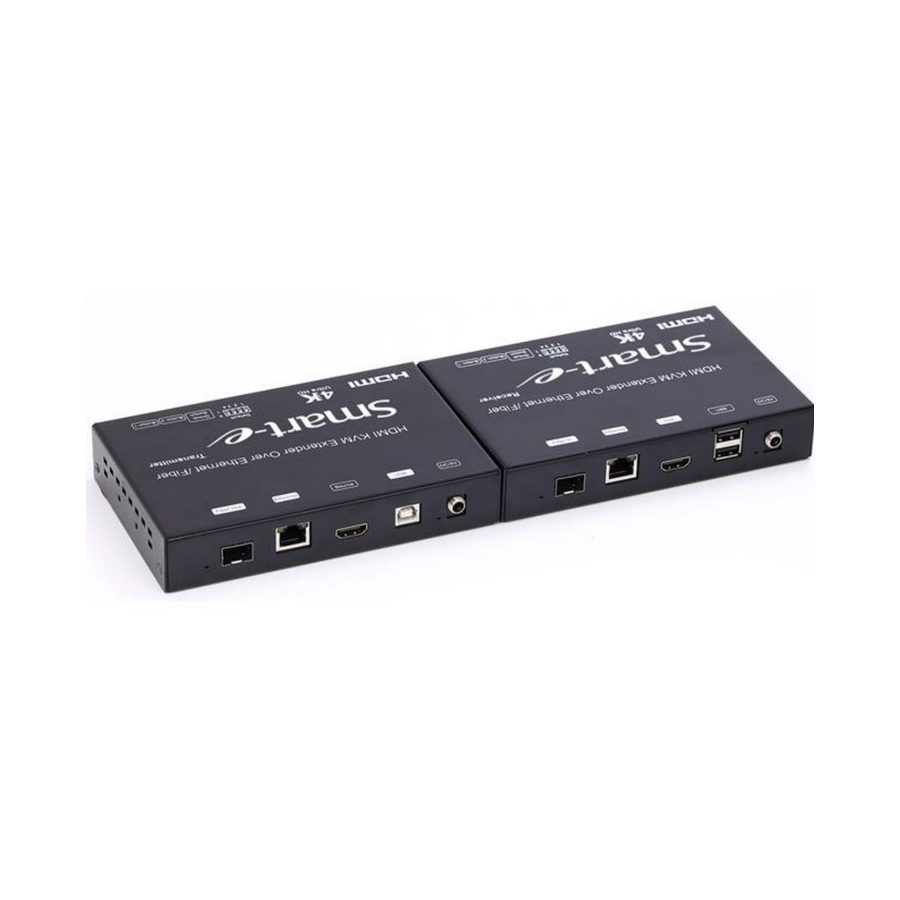
Page 7: Chassis Panel Description
After select the DIP switch, press “Group Switch” button for 1 second. Please refer to 5.3. 4 bits DIP Switch: Use 4bits DIP switch to select 16 groups ID (such as 0001, 0010, 0101 etc) © 2018 Smart-e (UK) Ltd www.smart-e.co.uk PAGE | 7... -
Page 8: Receiver
After select the DIP switch, press “Group Switch” button for 1 second. Please refer to 5.3. 4 bits DIP Switch: Use 4bits DIP switch to select 16 group ID (such as 0001, 0010, 0101 etc) © 2018 Smart-e (UK) Ltd www.smart-e.co.uk PAGE | 8... -
Page 9: Button Description
Engineering Mode* (Press until LED Blinking) Long Press on Boot Engineering Mode and Engineering Mode and (Press until both Red LED Reset to default* Reset to default* and Green LED Blinking) © 2018 Smart-e (UK) Ltd www.smart-e.co.uk PAGE | 9... - Page 10 1. This feature is only available on AST1510 and above. AST1500 will be by pass this event. 2. Enable/Disable Ethernet jumbo frame. 3. If link LED is solid then jumbo is enabled. If link LED is blinking then jumbo is disabled. © 2018 Smart-e (UK) Ltd www.smart-e.co.uk PAGE | 10...
- Page 11 Update EDID* (Press until Red LED Blinking) (>A1.2)* Long Press on Boot Engineering Mode and Engineering (Press until Reset to default* Mode and Red LED and Reset to default* Green LED Blinking) © 2018 Smart-e (UK) Ltd www.smart-e.co.uk PAGE | 11...
- Page 12 The selected client can gain control by pressing USB Link, and release control by pressing USB Link again. Other clients can also gain control by pressing USB Link. The control will be transfer to whichever client requests USB Link. © 2018 Smart-e (UK) Ltd www.smart-e.co.uk PAGE | 12...
- Page 13 1. This feature is only available on AST1510 and above. AST1500 will be by pass this event. 2. Enable/Disable Ethernet jumbo frame. 3. If link LED is solid then jumbo is enabled. If link LED is blinking then jumbo is disabled. © 2018 Smart-e (UK) Ltd www.smart-e.co.uk PAGE | 13...
-
Page 14: Installation
Power on the Transmitter, Receiver and all the connected devices. • Power on and activate all the connected devices. • Connect the IR extension cable with Transmitter and the IR receiver cable with Receiver for remote control. ◆ Configuration © 2018 Smart-e (UK) Ltd www.smart-e.co.uk PAGE | 14... - Page 15 4K-KVM USER MANUAL V1.1 ◆ Application Pattern ■ Unicast ■ Multicast a. Video Distribution Transmitter © 2018 Smart-e (UK) Ltd www.smart-e.co.uk PAGE | 15...
- Page 16 4K-KVM USER MANUAL V1.1 b. Matrix Distribution c. Billboard & Kiosk, PC to HDMI and USB Interactive Monitor © 2018 Smart-e (UK) Ltd www.smart-e.co.uk PAGE | 16...
-
Page 17: Pc Tool Instructions
3.2 PC TOOL INSTRUCTIONS Step 1: Make sure the HDMI extender and and PC are in the same domain. (Refer to 6.3) Step 2: Open the PC Tool. Step 3: Click “Scan”. © 2018 Smart-e (UK) Ltd www.smart-e.co.uk PAGE | 17... - Page 18 4K-KVM USER MANUAL V1.1 Step 4: Choose the TX or RX name. Step 5: Change the IP/Host name ID/Casting Mode/Multicast IP/IP Mode/ Device name on the PC tool interface. Step 6: Click “Apply”. © 2018 Smart-e (UK) Ltd www.smart-e.co.uk PAGE | 18...
-
Page 19: Multicast
3.2.1 MULTICAST Please Click "Multicast" on the PC tool under One to Many or Many to Many Mode. 3.2.2 GROUP ID Change the Group ID to view the same or different source. © 2018 Smart-e (UK) Ltd www.smart-e.co.uk PAGE | 19... -
Page 20: Video Wall
2. Change the “Vertical Monitor Count” and “Horizontal Monitor Count” the create video wall. For example, if you need create a 2x2 video wall, please set the “Vertical Monitor Count” and “Horizontal Monitor Count” as “2”. 3. Click “Show OSD”. © 2018 Smart-e (UK) Ltd www.smart-e.co.uk PAGE | 20... -
Page 21: Ip Configuration
1. Assign a LAN IP address to the computer in the same subnet. The IP address default of the Transmitter and Receiver is B class Networking: 169.254.xxx.xxx. Figure 1. Internet Protocol (TCP/IP) Properties © 2018 Smart-e (UK) Ltd www.smart-e.co.uk PAGE | 21... - Page 22 Then we can see all the IP address of both the TX and RX as shown below Remark: If the IP address with “Client”, It’s the IP address of the RX If the IP address with “Gateway”, It’s the IP address of the TX. © 2018 Smart-e (UK) Ltd www.smart-e.co.uk PAGE | 22...
- Page 23 Remember the Transmitter and Receiver IP address on monitor screen and then plug HDMI video source cable into Transmitter. Figure 3. Device IP Indication © 2018 Smart-e (UK) Ltd www.smart-e.co.uk PAGE | 23...
- Page 24 3. The administrator can input Transmitter or Receiver IP address into the address bar of a web browser (Recommend Google Chrome) to enter the Extender Web UI. If successful, the administrator will see the Web UI as shown in Figure 4. Figure 4. Web User Interface © 2018 Smart-e (UK) Ltd www.smart-e.co.uk PAGE | 24...
-
Page 25: Web User Interface Configuration
4K-KVM USER MANUAL V1.1 4 WEB USER INTERFACE CONFIGURATION 4.1 SYSTEM How to set up the connected extender and setting 4.1.1 [VERSION INFORMATION] Indicating the firmware version and relevant information of the devices © 2018 Smart-e (UK) Ltd www.smart-e.co.uk PAGE | 25... -
Page 26: Update Firmware]
It takes time to update the firmware. During the process of update, the Web user interface shows the status as below diagram. The extender system will reboot automatically after updating firmware. If it doesn’t reboot automatically, please reboot to apply the new firmware manually. © 2018 Smart-e (UK) Ltd www.smart-e.co.uk PAGE | 26... -
Page 27: Utilities]
Factory D e f a u l t : Click on to return to the factory default when necessary Reboot: Click on to reboot the extender system Console API Command: Input Linux command for advanced setting © 2018 Smart-e (UK) Ltd www.smart-e.co.uk PAGE | 27... -
Page 28: Statistics]
Default Gateway: 169.254.0.254 MAC Address: 82CA80853073 Casting Mode: unicast Mode Link Status: on Link Mode: Video Local Video Output: attached=n Video Timing Information: timing=[34] 640x480p@60Hz H- type=RGB HOCP=n (Disabl or depth=O © 2018 Smart-e (UK) Ltd www.smart-e.co.uk PAGE | 28... -
Page 29: Video Wall
1) The viewable width must be less than the outside width, and the viewable height must be less than the outside height. If administrator doesn’t need this, just set all values to 0. The unit is 0.1mm and the value MUST be integer. © 2018 Smart-e (UK) Ltd www.smart-e.co.uk PAGE | 29... - Page 30 4K-KVM USER MANUAL V1.1 Wall Size and Position Layout: Select number of vertical and/or horizontal monitors, row position and column position. Vertical monitor number 1~8, horizontal monitor number 1~16. © 2018 Smart-e (UK) Ltd www.smart-e.co.uk PAGE | 30...
- Page 31 4K-KVM USER MANUAL V1.1 Preferences: Select the video fit in the screen or stretch out and the rotate angle © 2018 Smart-e (UK) Ltd www.smart-e.co.uk PAGE | 31...
- Page 32 2) This (Local): The IP you input into address bar of web browser. 3) Hosts or Clients: select which Transmitter or Receiver you want to configure. Show OSD: Check this box to output each receiver’s specific number to the connected monitor © 2018 Smart-e (UK) Ltd www.smart-e.co.uk PAGE | 32...
- Page 33 Scrat:m L.Ayout (Row Column '-------, Position: PositiOt\: ·I uorl.zootal Shift: ·-' 1 --------.. Vertical Shift: • IIOI'i Z OOtal SCale Up (N piXeiS/COI UOII\_COunt): Vertical Scl!l lc Vp (N xcls/row_count): CoMole Comm and: © 2018 Smart-e (UK) Ltd www.smart-e.co.uk PAGE | 33...
- Page 34 Step1: In “Basic Setup”, select Vertical and Horizontal Monitor Count. For example Vertical Monitor Count = 3, Horizontal Monitor Count = 5 Sept2: In “Advanced Setup”, choose the target of the video wall to control © 2018 Smart-e (UK) Ltd www.smart-e.co.uk PAGE | 34...
- Page 35 Set up the number of vertical and horizontal monitor based on the video wall layout. Vertical number 1~8 and horizontal number 1~16. Setup the row position of monitor, number from 0 to the total number of vertical monitor. © 2018 Smart-e (UK) Ltd www.smart-e.co.uk PAGE | 35...
- Page 36 Horizontal Shift: Setup the video horizontal shift, Left or Right Vertical Shift: Setup the video vertical shift, Up or Down Horizontal Scale Up: Setup the video horizontal scale up Vertical Shift Scale Up: Setup the video vertical shift scale up. © 2018 Smart-e (UK) Ltd www.smart-e.co.uk PAGE | 36...
-
Page 37: Network
Consol API Command: Input Linux command to do advanced setup. 4.3 NETWORK: Update the network setup of the extender system 4.3.1 [IP SETUP] Auto IP: use automatically Extender assign IP system for example: 169.254.xxx.xxx. © 2018 Smart-e (UK) Ltd www.smart-e.co.uk PAGE | 37... - Page 38 4K-KVM USER MANUAL V1.1 © 2018 Smart-e (UK) Ltd www.smart-e.co.uk PAGE | 38...
-
Page 39: Casting Mode]
IP to assign manually. 4.3.2 [CASTING MODE] Select the broadcast mode of the extender application Multicast: point to multiple points or multiple point to multiple points broadcast Unicast: point to point broadcast © 2018 Smart-e (UK) Ltd www.smart-e.co.uk PAGE | 39... -
Page 40: Functions
4K-KVM USER MANUAL V1.1 4.4 FUNCTIONS: Setup the video output and USB extension mode for Transmitter Setup the video output and USB extension mode for Receiver © 2018 Smart-e (UK) Ltd www.smart-e.co.uk PAGE | 40... -
Page 41: Video Over Ip]
81000051: WUXGA 1920x1200@60 8100003C: SXGA+ 1400x1050@60 Timeout for Detecting Video Lost: Setup the time of stop the video storage when detecting video lost to transmit Customize Scalar Output Mode for Transmitter © 2018 Smart-e (UK) Ltd www.smart-e.co.uk PAGE | 41... -
Page 42: Usb Over Ip]
Enable USB over IP: Check to enable USB extension mode over IP Operation Mode: Including “auto select mode”, “active on line” and “active per request” modes for option. Compatibility Mode: Check to enable USB keyboard, USB mouse transmission mode © 2018 Smart-e (UK) Ltd www.smart-e.co.uk PAGE | 42... -
Page 43: Serial Over Ip
4.4.3 [SERIAL OVER IP] 1. Set up the serial extension mode 2. Select Type 2 as operation mode 3. Set up the baud rate for Type 2. Serial Over IP Broadcast Mode Setting © 2018 Smart-e (UK) Ltd www.smart-e.co.uk PAGE | 43... - Page 44 4K-KVM USER MANUAL V1.1 © 2018 Smart-e (UK) Ltd www.smart-e.co.uk PAGE | 44...
- Page 45 4K-KVM USER MANUAL V1.1 © 2018 Smart-e (UK) Ltd www.smart-e.co.uk PAGE | 45...
-
Page 46: Broadcast Configuration Setting
Install multiple transmitters and setting ID of these transmitters individually, edit the group of transmitters and receivers. The correspondent receivers will output the video from the transmitter belonged to the same group ID. © 2018 Smart-e (UK) Ltd www.smart-e.co.uk PAGE | 46... -
Page 47: Video Wall
And then follow the above steps to set the other extenders to the rest of row and column positions from 0x1, 0x2, 0x3 to 3x5 After the basic setup of the video wall, please access the advanced setup to proceed other detailed setting of the video output. © 2018 Smart-e (UK) Ltd www.smart-e.co.uk PAGE | 47... -
Page 48: Advanced Setup
Example for the video wall control Here’s the diagram of the actual video wall layout showing the selected monitor in the upper left corner with green outline. © 2018 Smart-e (UK) Ltd www.smart-e.co.uk PAGE | 48... - Page 49 Adjust the horizontal position of the video output, “Left/Right Shi ft ”, the selected monitor to adjust is shown with green outline. Adjust the vertical position of the video output, “Up/Down Shift”, the selected monitor to adjust is shown with green outline. © 2018 Smart-e (UK) Ltd www.smart-e.co.uk PAGE | 49...
- Page 50 Horizontal Scale Up: To scale up the video output horizontally as the monitor shown with green outline Vertical Scale Up: To scale up the video output vertically as the monitor shown with green outline...
-
Page 51: Warranty
The customer is responsible for maintaining proof of date of purchase. 2. Smart-e warranty covers only those defects which arise as a result of normal use of the product, and do not apply to any: a. Improper or inadequate maintenance or modifications b. Operations outside product specifications c.
Need help?
Do you have a question about the 4K-5W155 and is the answer not in the manual?
Questions and answers