
Related Manuals for Buderus Logamatic LON-Gateway


Summary of Contents for Buderus Logamatic LON-Gateway
-
Page 1: Technical Information
Technical Information Interface with DDC Logamatic LON-Gateway For heating contractors during project planning. -
Page 2: Table Of Contents
Logamatic LON-Gateway firmware ........ - Page 3 Contents 5 Incorporation of Logamatic 4000 in LON networks via Logamatic LON-Gateway . 39 Structure of the hardware ..........39 Creating LON networks .
-
Page 4: Explanation Of Symbols And Safety Instructions
Additional symbols Symbol Meaning Sequence of steps Cross-reference to other points in this document or to other documents • Listing/list entry – Listing/list entry (2nd level) Tab. 1 Technical Information Logamatic LON-Gateway - Subject to modifications resulting from technical improvements! -
Page 5: Safety Instructions
Damage from incorrect spare parts B Only use original Buderus spare parts. Damage caused by the use of spare parts not supplied by Buderus are excluded from the Buderus warranty. Technical Information Logamatic LON-Gateway - Subject to modifications resulting from technical improvements! -
Page 6: Product Description
Product description Product description 2.1 Correct use The Logamatic LON-Gateway may only be used to connect Buderus boilers with control panel from the Buderus Logamatic 4000 control series to superior control and/or building control systems via LON-BUS. 2.2 Disposal B Electronic components do not belong in household waste. -
Page 7: Product Description
Product description 2.3 Product description The Logamatic LON-Gateway is incorporated into a LON network via a twisted pair cable (twisted 2-wire line). The twisted pair cable is protected against reverse polarity. Defined data of the Buderus control panel is implemented with the Logamatic LON-Gateway interface on standard network variable types (SNVTs) for the LON data bus. -
Page 8: Specifications
DHW, and solar can be added. If heating zones are served via LON, no other remote controls, e.g. Buderus remote control BFU, may be connected to this heating zone. - Page 9 3) ECOCAN-BUS address of the Logamatic 4321 control panel on the first boiler; additional boilers with Logamatic 4321 control panel of the 4322 are assigned ECOCAN-BUS addresses 2 to 4. = Basic equipment = Optional (required accessories in parentheses) – = Not required Technical Information Logamatic LON-Gateway - Subject to modifications resulting from technical improvements!
-
Page 10: Logamatic Lon-Gateway Firmware
The update is complete. After the successful update, disconnect the LON-Gateway from the line voltage for approx. 2 minutes to perform a reset. This completes the firmware update. Technical Information Logamatic LON-Gateway - Subject to modifications resulting from technical improvements! -
Page 11: Network Interface
LON_Flasher_2B_00 LON_2B_00 Tab. 6 Communication via the Logamatic LON-Gateway takes place using standard network variable types (SNVT). Standard configuration parameter types (SCPTs) are not used. Set the system up for repeated reading of SNVTs, which ensure data exchange between the network participants. - Page 12 Change system supply set point temperature SNVT_temp_p(105) nviAnlVorgabe_Tp Display system supply actual temperature SNVT_temp_p(105) nvoAnlVLIst_Tp Display system return actual temperature SNVT_temp_p(105) nvoAnlRLIst_Tp Tab. 7 Service menu navigator Technical Information Logamatic LON-Gateway - Subject to modifications resulting from technical improvements!
- Page 13 Display solar yield (heat quantity) SNVT_elec_kwh_l (146) nvoSLWMZ_Ertrag SNVT_file_pos(90) nviParameter SNVT_file_pos(90) nviAdresse SNVT_file_pos(90) nvoMonitoring Tab. 7 Service menu navigator 1) Display of the output for boilers with Logamatic EMS Technical Information Logamatic LON-Gateway - Subject to modifications resulting from technical improvements!
-
Page 14: Description Of The Snvts For Variant 2 Boilers
The right column indicates the number of bytes. 3.2.1 General Time SNVT_time_ stamp(84) nviUhrzeit Tab. 8 Value for comparison of the time in the Buderus control system with the LON network Format: YYYY/MM/DD hh:mm:ss Outdoor temperature SNVT_temp_p(105) nvoAussen_Tp Tab. 9... - Page 15 Second, third, and fourth current errors in the control panel in question. List of the error list, see Chapter 7, page 43. Interpretation as described for error message 1. Technical Information Logamatic LON-Gateway - Subject to modifications resulting from technical improvements!
-
Page 16: Heating Zones
Tab. 15 Value for changing the set point temperature for the setback heating mode (night mode) Setting: 36 °F to 84 °F (2 °C to 29 °C) in 1-degree intervals Technical Information Logamatic LON-Gateway - Subject to modifications resulting from technical improvements! - Page 17 Tab. 19 Display of the currently-measured supply temperature for the consumer Note: 230 °F (110 °C) is an invalid value (e.g. no temperature sensor connected, sensor defective, etc.). Technical Information Logamatic LON-Gateway - Subject to modifications resulting from technical improvements!
-
Page 18: Dhw Heating
DHW menu. Recirculation pump operating SNVT_hvac_mode nviZP_TgNtAt mode (D/N/A) (108) Tab. 23 Value for changing the operating mode of the recirculation pump Technical Information Logamatic LON-Gateway - Subject to modifications resulting from technical improvements! - Page 19 230 °F (110 °C) is an invalid value (e.g. no temperature sensor connected, sensor defective, etc.). Recirculation pump SNVT_hvac_mode nvoZP_Betrieb operating mode (D/N/A) (108) Tab. 28 Display of the currently-selected operating mode for the recirculation pump Technical Information Logamatic LON-Gateway - Subject to modifications resulting from technical improvements!
-
Page 20: Strategy
230 °F (110 °C) is an invalid value (e.g. no temperature sensor connected, sensor defective, etc.). System return actual SNVT_temp_p(105) nvoAnlRLIst_Tp temperature Tab. 33 Display of the currently-measured return temperature for a floor-standing multi-boiler system Technical Information Logamatic LON-Gateway - Subject to modifications resulting from technical improvements! -
Page 21: Floor-Standing Boilers
Tab. 37 Display of the currently-measured supply temperature for a floor-standing multi-boiler system Note: 230 °F (110 °C) is an invalid value (e.g. no temperature sensor connected, sensor defective, etc.). Technical Information Logamatic LON-Gateway - Subject to modifications resulting from technical improvements! -
Page 22: Solar
Tab. 42 Display of the currently-measured actual temperature in the solar part of the DHW tank Note: 230 °F (110 °C) is an invalid value (e.g. no temperature sensor connected, sensor defective, etc.). Technical Information Logamatic LON-Gateway - Subject to modifications resulting from technical improvements! -
Page 23: Overview Of The Snvts For Variant 4 Boilers
Logamatic 4000 Tab. 44 Communication via the Logamatic LON-Gateway takes place using standard network variable types (SNVT). Standard configuration parameter types (SCPTs) are not used. For the data exchange between the network devices to work properly, set up the cyclical query of the SNVTs. - Page 24 Pump 4000 boiler 2 SNVT_lev_cont (21) nvoKS2PU_4000 Burner hours of operation EMS boiler 2 SNVT_time_hour(124) nvoKS1Br_EMS_h Pump EMS boiler 2 SNVT_lev_cont (21) nvoKS1PU_EMS Tab. 45 Service menu navigator Technical Information Logamatic LON-Gateway - Subject to modifications resulting from technical improvements!
- Page 25 Burner hours of operation EMS boiler 4 SNVT_time_hour(124) nvoKS4BrEMS_h Pump EMS boiler 4 SNVT_lev_cont (21) nvoKS4PU_EMS Status Status ECOCAN-BUS SNVT_state(83) nvo_CAN_Adressen Status LON version SNVT_str_asc (36) nvo_LONVersion Tab. 45 Service menu navigator Technical Information Logamatic LON-Gateway - Subject to modifications resulting from technical improvements!
-
Page 26: Description Of The Snvts For Variant 4 Boilers
3.4 Description of the SNVTs for variant 4 boilers 3.4.1 General Time SNVT_time_ stamp(84) nviUhrzeit Tab. 46 Value for comparison of the time in the Buderus control system with the LON network Format: YYYY/MM/DD hh:mm:ss Outdoor temperature SNVT_temp_p(105) nvoAussen_Tp Tab. 47 Display of the current outdoor temperature Note: 230 °F (110 °C) is an invalid value (e.g. - Page 27 3. Errors that occur are to be interpreted as follows: First byte - error control panel 2 Second byte - error control panel 1 Display Interpretation Tab. 53 Interpretation as described for error messages boiler 1, 2. Technical Information Logamatic LON-Gateway - Subject to modifications resulting from technical improvements!
-
Page 28: Heating Zones
Tab. 56 Value for changing the set point temperature for the setback heating mode (night mode) Setting: 36 °F to 84 °F (2 °C to 29 °C) in 1-degree intervals Technical Information Logamatic LON-Gateway - Subject to modifications resulting from technical improvements! - Page 29 Tab. 60 Display of the currently-measured supply temperature for the consumer Note: 230 °F (110 °C) is an invalid value (e.g. no temperature sensor connected, sensor defective, etc.). Technical Information Logamatic LON-Gateway - Subject to modifications resulting from technical improvements!
-
Page 30: Dhw Heating
• If for DHW heating temperatures > 140 °F (60 °C) are desired, the range up to 176 °F (80 °C) can be released on the service level in the DHW menu. Recirculation pump operating SNVT_hvac_mode nviZP_TgNtAt mode (D/N/A) (108) Tab. 64 Value for changing the operating mode Technical Information Logamatic LON-Gateway - Subject to modifications resulting from technical improvements! - Page 31 230 °F (110 °C) is an invalid value (e.g. no temperature sensor connected, sensor defective, etc.). Recirculation pump SNVT_hvac_mode nvoZP_Betrieb operating mode (D/N/A) (108) Tab. 69 Display of the currently-selected operating mode for the recirculation pump Technical Information Logamatic LON-Gateway - Subject to modifications resulting from technical improvements!
-
Page 32: Strategy
Tab. 74 Display of the currently-measured supply temperature for the boiler system Note: 230 °F (110 °C) is an invalid value (e.g. no temperature sensor connected, sensor defective, etc.). Technical Information Logamatic LON-Gateway - Subject to modifications resulting from technical improvements! -
Page 33: Boiler 1
1 level 1 Tab. 79 Display of the hours of operation for the level 1 (basic load) of boiler 1 with Logamatic 4000 and third party burner Technical Information Logamatic LON-Gateway - Subject to modifications resulting from technical improvements! - Page 34 Tab. 85 Operating message for the boiler circulation pump of the boiler 1 with Logamatic EMS Pump OFF [0 %] ON [> 0 %] Current output [%] Technical Information Logamatic LON-Gateway - Subject to modifications resulting from technical improvements!
-
Page 35: Boiler 2
ON [> 0 %] Current output [%] Burner hours of operation EMS SNVT_time_hour(124) nvoKS1Br_EMS_h boiler 2 Tab. 91 Display of the hours of operation for boiler with Logamatic EMS Technical Information Logamatic LON-Gateway - Subject to modifications resulting from technical improvements! - Page 36 SNVT_lev_cont (21) nvoKS1PU_EMS Tab. 92 Operating message for the boiler circulation pump of the boiler with Logamatic EMS Pump OFF [0 %] ON [> 0 %] Current output [%] Technical Information Logamatic LON-Gateway - Subject to modifications resulting from technical improvements!
-
Page 37: Status
2 3 4 5 6 7 8 9 0 C A N L O N "CAN V. XX.YY" indicates the firmware version of the LON-Gateway. "LON V.XX.YY" indicates the software version of the LON-Gateway (XIF file). Technical Information Logamatic LON-Gateway - Subject to modifications resulting from technical improvements! -
Page 38: Operating Basics
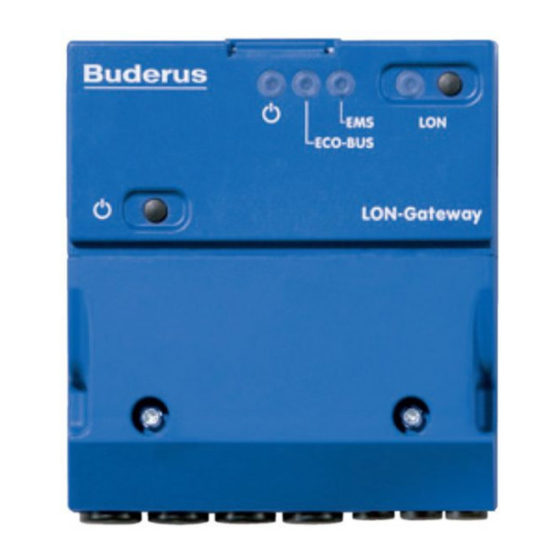
"LON" LED flashes for the successful commissioning of the LON-Gateway. "LON" service button Tab. 95 Key to Fig. 2 If the EMS LED lights up, there is a communication problem on the ECOCAN-BUS. B Check the cable. Technical Information Logamatic LON-Gateway - Subject to modifications resulting from technical improvements! -
Page 39: Incorporation Of Logamatic 4000 In Lon Networks Via Logamatic Lon-Gateway
(for details, see Chapter 3). Input network variables (nvi) and output network variables (nvo) of the various products are connected to one another in the PC software. This way, the required functions are created in the PC software. Technical Information Logamatic LON-Gateway - Subject to modifications resulting from technical improvements! -
Page 40: Commissioning Lon Networks
For each LON node that is incorporated into this software, license fees in the form of credits are from Echelon. Since the neuron ID is unique, before removing the device, the decommissioning via the PC software is recommended. Technical Information Logamatic LON-Gateway - Subject to modifications resulting from technical improvements! -
Page 41: The Lon-Gateway As Lonmark Object
The LON-Gateway as LonMark object The LON-Gateway as LonMark object 6.1 Variant 2 boiler Fig. 3 Buderus function block (variant 2 boiler) Technical Information Logamatic LON-Gateway - Subject to modifications resulting from technical improvements! -
Page 42: Variant 4 Boiler
The LON-Gateway as LonMark object 6.2 Variant 4 boiler Fig. 4 Buderus function block (variant 4 boiler) Technical Information Logamatic LON-Gateway - Subject to modifications resulting from technical improvements! -
Page 43: Error List
Boiler remains cold Boiler 2 no connection fault Burner fault Boiler 3 no connection fault Safety sequence fault Boiler 4 no connection fault External fault boiler Tab. 96 Error list Technical Information Logamatic LON-Gateway - Subject to modifications resulting from technical improvements! - Page 44 Manual switch heating zone 8 Address conflict 2 fault DHW manual switch Address conflict 3 fault Manual burner switch Address conflict 4 fault Manual switch for boiler loop Tab. 96 Error list Technical Information Logamatic LON-Gateway - Subject to modifications resulting from technical improvements!
- Page 45 EMS boiler 4 manual mode Solar heat quantity supply sensor fault EMS boiler 5 manual mode Solar heat quantity return sensor fault EMS boiler 6 manual mode Tab. 96 Error list Technical Information Logamatic LON-Gateway - Subject to modifications resulting from technical improvements!
- Page 46 Sensor buffer tank center Sensor buffer tank bottom Sensor buffer tank top Sensor system return Sensor heat source flue gas No communication FA heat source Tab. 96 Error list Technical Information Logamatic LON-Gateway - Subject to modifications resulting from technical improvements!
- Page 47 1) KNX = Konnex (arose from a combination of EIB with additional bus systems) For information about troubleshooting, please see the included documentation for the boiler or the control panel. Technical Information Logamatic LON-Gateway - Subject to modifications resulting from technical improvements!
- Page 48 United States and Canada Bosch Thermotechnology Corp. 50 Wentworth Avenue Londonderry, NH 03053 Tel. 603-552-1100 Fax 603-584-1681 www.buderus.us U.S.A. Products manufactured by Bosch Thermotechnik GmbH Sophienstrasse 30-32 D-35576 Wetzlar www.buderus.com Bosch Thermotechnology Corp. reserves the right to make changes without notice due to continuing...
Need help?
Do you have a question about the Logamatic LON-Gateway and is the answer not in the manual?
Questions and answers