GORMAN-RUPP PUMPS 60 Series Installation, Operation, And Maintenance Manual With Parts List
Hide thumbs
Also See for 60 Series:
Table of Contents
Advertisement
Quick Links
Advertisement
Table of Contents

Related Manuals for GORMAN-RUPP PUMPS 60 Series


Summary of Contents for GORMAN-RUPP PUMPS 60 Series
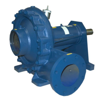
- Page 1 ACDE OM−04407-03 May 6, 2004 INSTALLATION, OPERATION, AND MAINTENANCE MANUAL WITH PARTS LIST 60 SERIES PUMP MODEL 612M60−B THE GORMAN-RUPP COMPANY D MANSFIELD, OHIO www.grpumps.com GORMAN-RUPP OF CANADA LIMITED ST. THOMAS, ONTARIO, CANADA Printed in U.S.A. 2004 The Gorman-Rupp Company...
- Page 2 Register your new Gorman-Rupp pump online at www.grpumps.com Valid serial number and e-mail address required. RECORD YOUR PUMP MODEL AND SERIAL NUMBER Please record your pump model and serial number in the spaces provided below. Your Gorman-Rupp distributor needs this information when you require parts or service. Pump Model: Serial Number:...
-
Page 3: Table Of Contents
TABLE OF CONTENTS INTRODUCTION ..........PAGE I −... - Page 4 TABLE OF CONTENTS (continued) PARTS LIST: Pump Model ............PAGE E −...
-
Page 5: Introduction
Rupp pump. to those which could be dangerous to personnel: This pump is a 60 Series, enclosed impeller, straight centrifugal basic pump model. The pump is designed for handling most non-volatile, non- flammable liquids containing specified entrained solids. -
Page 6: Safety - Section A
60 SERIES OM−04407 SAFETY - SECTION A This information applies to 60 Series ba- sive or flammable liquids which may sic pumps. Gorman-Rupp has no con- damage the pump or endanger person- trol over or particular knowledge of the nel as a result of pump failure. - Page 7 OM−04407 60 SERIES Do not operate the pump without shields and/or guards in place over the drive shafts, belts, and/or couplings, or other rotating parts. Exposed rotating parts can catch clothing, fingers, or tools, causing severe injury to person- nel.
-
Page 8: Installation − Section Bpage B
60 SERIES OM−04407 INSTALLATION − SECTION B Review all SAFETY information in Section A. configuration, and priming must be tailored to the specific application. Since the pressure supplied to the pump is critical to performance and safety, Since pump installations are seldom identical, this... -
Page 9: Positioning Pump
OM−04407 60 SERIES c. Carefully read all tags, decals, and markings and move the unit are improperly wrapped on the pump assembly, and perform all duties around the pump. indicated. Note that the pump shaft rotates in Mounting the required direction. -
Page 10: Gauges
60 SERIES OM−04407 Gauges Sealing Since even a slight leak will affect priming, head, Most pumps are drilled and tapped for installing and capacity, especially when operating with a discharge pressure and vacuum suction gauges. If high suction lift, all connections in the suction line... -
Page 11: Discharge Lines
OM−04407 60 SERIES Figure B−2. Recommended Minimum Suction Line Submergence vs. Velocity DISCHARGE LINES Siphoning If the application involves a high discharge Do not terminate the discharge line at a level lower head, gradually close the discharge than that of the liquid being pumped unless a si- throttling valve before stopping the pump. -
Page 12: Coupled Drives
60 SERIES OM−04407 is imperative that alignment be checked after the pump and piping are installed, and before opera- tion. NOTE Check Rotation, Section C, before final alignment of the pump. Figure B−3. Alignment of V-Belt Driven Pumps When mounted at the Gorman-Rupp factory, driver and pump are aligned before shipment. - Page 13 OM−04407 60 SERIES Tighten the belts in accordance with the belt manu- facturer’s instructions. If the belts are too loose, they will slip; if the belts are too tight, there will be excessive power loss and possible bearing failure. Select pulleys that will match the proper speed ra- tio;...
-
Page 14: Operation − Section C
OM−04407 60 SERIES OPERATION − SECTION C Review all SAFETY information in Section A. coming liquid to evacuate the air. After the pump and piping system have completely filled, evacu- Follow the instructions on all tags, labels and ate any remaining air pockets in the pump or suc- decals attached to the pump. -
Page 15: Operation
OM−04407 60 SERIES incorrect on a single-phase motor, consult the lit- pressure, and cause the pump casing to erature supplied with the motor for specific instruc- rupture or explode. tions. Leakage OPERATION No leakage should be visible at pump mating sur- Lines With a Bypass faces, or at pump connections or fittings. -
Page 16: Strainer Check
OM−04407 60 SERIES valve with a substitute which has not been speci- fied or provided by the Gorman-Rupp Company. If the application involves a high discharge Strainer Check head, gradually close the discharge throttling valve before stopping the pump. If a suction strainer has been shipped with the... -
Page 17: Troubleshooting − Section D
60 SERIES OM−04407 TROUBLESHOOTING − SECTION D Review all SAFETY information in Section A. Before attempting to open or service the pump: 1. Familiarize yourself with this manual. 2. Lock out or disconnect the power source to ensure that the pump will remain inoperative. - Page 18 OM−04407 60 SERIES TROUBLE POSSIBLE CAUSE PROBABLE REMEDY Impeller or other wearing parts worn Replace worn or damaged parts. PUMP STOPS OR FAILS TO DELIVER or damaged. Check that impeller is properly RATED FLOW OR centered and rotates freely. PRESSURE (cont.) Strainer clogged.
-
Page 19: Preventive Maintenance Schedule
60 SERIES OM−04407 equipped) between regularly scheduled inspec- PREVENTIVE MAINTENANCE tions can indicate problems that can be corrected Since pump applications are seldom identical, and before system damage or catastrophic failure oc- pump wear is directly affected by such things as curs. -
Page 20: Pump Maintenance And Repair - Section E
60 SERIES OM−04407 PUMP MAINTENANCE AND REPAIR - SECTION E MAINTENANCE AND REPAIR OF THE WEARING PARTS OF THE PUMP WILL MAINTAIN PEAK OPERATING PERFORMANCE. STANDARD PERFORMANCE FOR PUMP MODEL 612M60−B Based on 70_ F (21_ C) clear water at sea level Contact the Gorman-Rupp Company to verify per- formance or part numbers. - Page 21 OM−04407 60 SERIES PARTS PAGE SECTION DRAWING Figure 1. Pump Model 612M60−B PAGE E − 2 MAINTENANCE & REPAIR...
-
Page 22: Parts List
60 SERIES OM−04407 PARTS LIST Pump Model 612M60−B (From S/N 1453214 Up) If your pump serial number is followed by an N", your pump is NOT a standard production model. Contact the Gorman-Rupp Company to verify part numbers. ITEM PART NAME PART MAT’L... - Page 23 OM−04407 60 SERIES SECTION DRAWING IMPELLER WEAR RING NOTE: UNLESS OTHERWISE SPECIFIED, MACHINED SURFACES TO BE 125 RMS. Figure 2. Impeller Assembly Machining Tolerances PAGE E − 4 MAINTENANCE & REPAIR...
- Page 24 60 SERIES OM−04407 PUMP AND SEAL DISASSEMBLY 4. Check the temperature before opening any covers, plates, or AND REASSEMBLY plugs. 5. Close the suction and discharge Review all SAFETY information in Section A. valves. 6. Vent the pump slowly and cau- Follow the instructions on all tags, label and de- tiously.
- Page 25 OM−04407 60 SERIES NOTE welded to the impeller. Failure to properly install the wear ring and machine and bal- When removing the pump casing, use a wire to se- ance the impeller assembly can result in cure the assembled bottle oiler (60) and bracket (63) above the level of the oil in the seal cavity.
- Page 26 60 SERIES OM−04407 Shaft and Bearing Removal and Disassembly Bearing Cleaning And Inspection Clean the bearing housing, shaft and all compo- When the pump is properly operated and main- nent parts (except the bearings) with a soft cloth tained, the pedestal should not require disassem- soaked in cleaning solvent.
- Page 27 OM−04407 60 SERIES be replaced any time the shaft and bear- ings are removed. The bearings may be heated to ease installation. When installing the bearings onto the An induction heater, hot oil bath, electric oven, or shaft, never press or hit against the outer hot plate may be used to heat the bearings.
- Page 28 60 SERIES OM−04407 Seal Reassembly and Installation The seal is not normally reused because wear pat- terns on the finished faces cannot be realigned (Figures E−1 and E−3) during reassembly. This could result in premature failure. If necessary to reuse an old seal in an emer-...
- Page 29 OM−04407 60 SERIES SPRING RETAINER SEAL PLATE IMPELLER SHAFT STATIONARY SLEEVE ELEMENT O-RING SHAFT IMPELLER SLEEVE ROTATING SHAFT ELEMENT O-RINGS BELLOWS STATIONARY SEAT IMPELLER SHIMS Figure E−3. Seal Assembly Lubricate the seal sleeve O-ring with a small amount of light oil and install it in the groove in the I.D.
- Page 30 60 SERIES OM−04407 After the impeller clearance has been set, align the quires machining and dynamic balancing pin in the impeller washer (40) with the hole in the the impeller assembly after the wear ring is impeller and install the washer. Apply Never- welded to the impeller.
- Page 31 OM−04407 60 SERIES Turn the impeller shaft by hand and check for any tioned horizontally to provide proper drainage. scraping or binding and correct it before putting the pump into service. Under normal conditions, drain the bearing hous- ing once each year and refill with approximately 14 LUBRICATION ounces (0,4 liter) of clean oil.
- Page 32 For U.S. and International Warranty Information, Please Visit www.grpumps.com/warranty or call: U.S.: 419−755−1280 International: +1−419−755−1352 For Canadian Warranty Information, Please Visit www.grcanada.com/warranty or call: 519−631−2870 THE GORMAN-RUPP COMPANY D MANSFIELD, OHIO GORMAN-RUPP OF CANADA LIMITED ST. THOMAS, ONTARIO, CANADA...
Need help?
Do you have a question about the 60 Series and is the answer not in the manual?
Questions and answers