GORMAN-RUPP PUMPS 60 Series Installation, Operation And Maintenance Manual
Hide thumbs
Also See for 60 Series:
Table of Contents
Advertisement
Quick Links
ACE
OM−01395−02
July 8, 1985
Rev. C 10-09-06
INSTALLATION, OPERATION,
AND MAINTENANCE MANUAL
WITH PARTS LIST
60 SERIES PUMP
MODEL
612L20−B
THE GORMAN-RUPP COMPANY D MANSFIELD, OHIO
www.grpumps.com
D
GORMAN-RUPP OF CANADA LIMITED
ST. THOMAS, ONTARIO, CANADA
Printed in U.S.A.
e
Copyright by the Gorman-Rupp Company
Advertisement
Table of Contents

Related Manuals for GORMAN-RUPP PUMPS 60 Series


Summary of Contents for GORMAN-RUPP PUMPS 60 Series
- Page 1 OM−01395−02 July 8, 1985 Rev. C 10-09-06 INSTALLATION, OPERATION, AND MAINTENANCE MANUAL WITH PARTS LIST 60 SERIES PUMP MODEL 612L20−B THE GORMAN-RUPP COMPANY D MANSFIELD, OHIO www.grpumps.com GORMAN-RUPP OF CANADA LIMITED ST. THOMAS, ONTARIO, CANADA Printed in U.S.A. Copyright by the Gorman-Rupp Company...
- Page 2 Register your new Gorman-Rupp pump online at www.grpumps.com/register. Valid serial number and e-mail address required. RECORD YOUR PUMP MODEL AND SERIAL NUMBER Please record your pump model and serial number in the spaces provided below. Your Gorman-Rupp distributor needs this information when you require parts or service. Pump Model: Serial Number:...
-
Page 3: Table Of Contents
TABLE OF CONTENTS INTRODUCTION ..........PAGE I −... - Page 4 TABLE OF CONTENTS (continued) PUMP MAINTENANCE AND REPAIR - SECTION E ....PAGE E − 1 STANDARD PERFORMANCE CURVE ........PAGE E −...
-
Page 5: Introduction
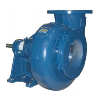
This pump is a 60 Series, enclosed impeller, centrif- ugal model with straight-in suction, without a suc- tion check valve. The pump is designed for handl- ing wastewater, mud or slurries containing speci- fied entrained solids. -
Page 6: Safety - Section A
60 SERIES OM−01395 SAFETY - SECTION A This information applies to 60 Series ba- liquids which may damage the pump or sic pumps. Gorman-Rupp has no con- endanger personnel as a result of pump trol over or particular knowledge of the failure. - Page 7 OM−01395 60 SERIES shields and/or guards in place over the drive shafts, belts, and/or couplings, or other rotating parts. Exposed rotating parts can catch clothing, fingers, or Pumps and related equipment must be in- tools, causing severe injury to person- stalled and operated according to all na- nel.
-
Page 8: Installation − Section Bpage B
60 SERIES OM−01395 INSTALLATION − SECTION B Review all SAFETY information in Section A. specific application. Since the pressure supplied to the pump is critical to performance and safety, Since pump installations are seldom identical, this be sure to limit the incoming pressure to 50% of the... -
Page 9: Positioning Pump
OM−01395 60 SERIES ing, check for loose hardware at mating sur- faces. c. Carefully read all tags, decals, and markings The pump assembly can be seriously on the pump assembly, and perform all duties damaged if the chains or cables used to lift indicated. -
Page 10: Gauges
60 SERIES OM−01395 cause excessive vibration, decreased bearing life, three or four times the cross section of the suction and increased shaft and seal wear. If hose-type line, and that the openings will not permit passage lines are used, they should have adequate support... -
Page 11: Discharge Lines
OM−01395 60 SERIES by installing a standard pipe increaser fitting at the on the increased opening size (area or diameter). end of the suction line. The larger opening size will reduce the inlet velocity. Calculate the required submergence using the following formula based Figure B−2. -
Page 12: Coupled Drives
60 SERIES OM−01395 NOTE Check Rotation, Section C, before final alignment of the pump. When mounted at the Gorman-Rupp factory, driver and pump are aligned before shipment. Misalign- Figure B−3. Aligning Spider-Type Couplings ment will occur in transit and handling. Pumps must be checked and realigned before operation. -
Page 13: V-Belt Jack Shaft Drives
OM−01395 60 SERIES Select pulleys that will match the proper speed ra- tio; overspeeding the pump may damage both pump and power source. Do not operate the pump without the guard in place over the rotating parts. Exposed rotating parts can catch cloth-... -
Page 14: Operation − Section C
OM−01395 60 SERIES OPERATION − SECTION C Review all SAFETY information in Section A. 2. The pump has not been used for a consider- able length of time. Follow the instructions on all tags, labels and 3. The liquid in the pump casing has evapo- decals attached to the pump. -
Page 15: Starting
OM−01395 60 SERIES STARTING Liquid Temperature And Overheating Consult the operations manual furnished with the The maximum liquid temperature for this pump is power source. 160_ F (71_C). Do not apply it at a higher operating temperature. Starting procedures will vary slightly depending on... -
Page 16: Pump Vacuum Check
OM−01395 60 SERIES Pump Vacuum Check Cold Weather Preservation In below freezing conditions, drain the pump to Since this pump does not have a suction check prevent damage from freezing. Also, clean out any valve, the discharge line must be fitted with a check solids by flushing with a hose. -
Page 17: Troubleshooting − Section D
60 SERIES OM−01395 TROUBLESHOOTING − SECTION D Review all SAFETY information in Section A. Before attempting to open or service the pump: 1. Familiarize yourself with this manual. 2. Lock out or disconnect the power source to ensure that the pump will remain inoperative. - Page 18 OM−01395 60 SERIES TROUBLE POSSIBLE CAUSE PROBABLE REMEDY Impeller or other wearing parts worn Replace worn or damaged parts. PUMP STOPS OR FAILS TO DELIVER or damaged. Check that impeller is properly RATED FLOW OR centered and rotates freely. PRESSURE (cont.) Strainer clogged.
-
Page 19: Preventive Maintenance
60 SERIES OM−01395 PREVENTIVE MAINTENANCE equipped) between regularly scheduled inspec- tions can indicate problems that can be corrected Since pump applications are seldom identical, and before system damage or catastrophic failure oc- pump wear is directly affected by such things as curs. - Page 20 60 SERIES OM−01395 PUMP MAINTENANCE AND REPAIR - SECTION E MAINTENANCE AND REPAIR OF THE WEARING PARTS OF THE PUMP WILL MAINTAIN PEAK OPERATING PERFORMANCE. STANDARD PERFORMANCE FOR PUMP MODEL 612L20−B Based on 70_ F (21_ C) clear water at sea level Contact the Gorman-Rupp Company to verify per- formance or part numbers.
- Page 21 OM−01395 60 SERIES PARTS PAGE SECTION DRAWING Figure 1. Pump Model 612L20−B PAGE E − 2 MAINTENANCE & REPAIR...
- Page 22 60 SERIES OM−01395 PARTS LIST Pump Model 612L20−B (From S/N 814882 up) If your pump serial number is followed by an N", your pump is NOT a standard production model. Contact the Gorman-Rupp Company to verify part numbers. ITEM PART NAME PART MAT’L...
- Page 23 OM−01395 60 SERIES PUMP AND SEAL DISASSEMBLY 4. Check the temperature before opening any covers, plates, or AND REASSEMBLY plugs. 5. Close the suction and discharge Review all SAFETY information in Section A. valves. 6. Vent the pump slowly and cau- Follow the instructions on all tags, label and de- tiously.
- Page 24 60 SERIES OM−01395 Support the pump casing using a suitable hoist NOTE and sling. If necessary, heat the impeller with a torch to aid in the removal. Remove the hardware (5 and 38) securing the pump casing to the pedestal.
- Page 25 OM−01395 60 SERIES Remove the machine screws (12) and slide the Press the oil seal out of the bearing cap. seal plate, remaining stationary mechanical seal Place a block of wood against the impeller end of components, and oil seal off the shaft as a unit. Be...
- Page 26 60 SERIES OM−01395 the balls or rollers are discolored, replace the bear- small nicks and burrs with a fine file or emery cloth. ings. Replace the shaft if defective. The bearing tolerances provide a tight press fit NOTE onto the shaft and a snug slip fit into the pedestal.
- Page 27 OM−01395 60 SERIES Seal Reassembly and Installation (Figures 1 and 2) Clean the seal cavity and shaft with a cloth soaked When installing the bearings onto the in fresh cleaning solvent. shaft, never press or hit against the outer race, balls, or ball cage. Press only on the inner race.
- Page 28 60 SERIES OM−01395 RETAINER SEAL PLATE SPRING O-RINGS IMPELLER STATIONARY ELEMENT IMPELLER SHAFT OIL SEAL BELLOWS STATIONARY ROTATING SEAT ELEMENT Figure E−4. 12590B Seal Assembly Reinstall the air vent and piping (6, 7 and 8) and bottle oiler and piping (9, 10 and 11). Lubricate the seal assembly as indicated in LUBRICATION, af- ter the impeller is installed.
- Page 29 OM−01395 60 SERIES Remove the setscrews (41) from the impeller nut LUBRICATION (42). Apply Never-Seez" or equivalent compound Seal Assembly to the shaft threads and screw the impeller nut onto the shaft. Immobilize the impeller as shown in Fig- Fill the bottle oiler (9) with SAE No. 30 non-deter- ure E−2, and torque the impeller nut to 300 ft.
- Page 30 AV−05791 (02-07-06) THE GORMAN-RUPP COMPANY AND GORMAN-RUPP OF CANADA LIMITED 12 MONTH LIMITED WARRANTY EXTENT AND DURATION OF WARRANTY Coverage: The Gorman-Rupp Company or Gorman-Rupp of Canada Limited (herein individually referred to as GR") each individually warrant that its products and parts shall be free from defects in material and workmanship for twelve (12) months from the date of purchase by the original end user.
Need help?
Do you have a question about the 60 Series and is the answer not in the manual?
Questions and answers