GORMAN-RUPP PUMPS 60 Series Installation, Operation, And Maintenance Manual With Parts List
Hide thumbs
Also See for 60 Series:
Table of Contents
Advertisement
Quick Links
C+PP
COM-05171-OE01
January 5, 2001
REV A 09/14/10
INSTALLATION, OPERATION,
AND MAINTENANCE MANUAL
WITH PARTS LIST
60 SERIES PUMP
MODEL
62 1/2D1-CH23 S/G
THE GORMAN‐RUPP COMPANY D MANSFIELD, OHIO
D
GORMAN‐RUPP OF CANADA LIMITED
ST. THOMAS, ONTARIO, CANADA
Printed in U.S.A.
E
Copyright by the Gorman‐Rupp Company
Advertisement
Table of Contents

Related Manuals for GORMAN-RUPP PUMPS 60 Series


Summary of Contents for GORMAN-RUPP PUMPS 60 Series
- Page 1 C+PP COM-05171-OE01 January 5, 2001 REV A 09/14/10 INSTALLATION, OPERATION, AND MAINTENANCE MANUAL WITH PARTS LIST 60 SERIES PUMP MODEL 62 1/2D1-CH23 S/G THE GORMAN‐RUPP COMPANY D MANSFIELD, OHIO GORMAN‐RUPP OF CANADA LIMITED ST. THOMAS, ONTARIO, CANADA Printed in U.S.A.
- Page 2 Register your new Gorman‐Rupp pump online at www.grpumps.com Valid serial number and e‐mail address required. RECORD YOUR PUMP MODEL AND SERIAL NUMBER Please record your pump model and serial number in the spaces provided below. Your Gorman‐Rupp distributor needs this information when you require parts or service. Pump Model: Serial Number:...
-
Page 3: Table Of Contents
TABLE OF CONTENTS INTRODUCTION ........... PAGE I - 1 SAFETY - SECTION A . - Page 4 TABLE OF CONTENTS (continued) Discharge Check Valve Disassembly ........PAGE E - 7 Exhaust Primer Disassembly .
-
Page 5: Introduction
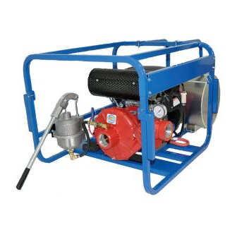
Rupp pump. aluminum with bronze wear ring, and a self lubri cated mechanical seal. This pump is a 60 Series, single‐stage centrifugal model designed for agricultural or fire fighting ser vice. It is close‐coupled to a Kohler CH23 v‐twin cyl... -
Page 7: Safety - Section A
60 SERIES OM-05171 SAFETY - SECTION A This information applies to 60 Series Engine Driven pumps. Refer to the man ual accompanying the engine before at tempting to begin operation. This pump is designed to handle clear water for high pressure distribution. Do... - Page 8 60 SERIES OM-05171 and fire hazard. Make certain that all fuel lines are securely connected and free of leaks. Never refuel a hot or run ning engine. Avoid overfilling the fuel Never tamper with the governor to gain tank. Always use the correct type of fuel.
-
Page 9: Installation - Section B
60 SERIES OM-05171 INSTALLATION - SECTION B Review all SAFETY information in Section A. specific application. Since the pressure supplied to the pump is critical to performance and safety, Since pump installations are seldom identical, this be sure to limit the incoming pressure to 50% of... -
Page 10: Positioning Pump
OM-05171 60 SERIES c. Carefully read all tags, decals and markings To ensure sufficient lubrication and fuel supply to on the pump assembly, and follow the instruc the engine, do not position the pump and engine tions indicated. more than 15_ off horizontal for continuous opera... -
Page 11: Suction Lines
60 SERIES OM-05171 these gauges are desired for pumps that are not Sealing tapped, drill and tap the suction and discharge Since even a slight leak will affect priming, head, lines not less than 18 inches (457,2 mm) from the and capacity, especially when operating with a suction and discharge ports and install the lines. -
Page 12: Discharge Lines
OM-05171 60 SERIES Figure 2. Recommended Minimum Suction Line Submergence vs. Velocity DISCHARGE LINES If a throttling valve is desired in the discharge line, use a valve as large as the largest pipe to minimize Siphoning friction losses. Never install a throttling valve in a suction line. -
Page 13: Operation - Section C
OM-05171 60 SERIES OPERATION - SECTION C Review all SAFETY information in Section A. The exhaust primer utilizes engine exhaust gases, directed through a venturi, to create a vacuum and Follow the instructions on all tags, labels and draw air out of the suction line and pump casing. -
Page 14: Operation
OM-05171 60 SERIES Set the twist‐lock throttle control at approximately heated pump. Vapor pressure within the half open position. Start the engine and follow en pump can cause parts being disen gine manufacturer's recommendations for carbu gaged to be ejected with great force. Al... -
Page 15: Cold Weather Preservation
OM-05171 60 SERIES prevent damage from freezing. Also, clean out any solids by flushing with a hose. Operate the pump for approximately one minute; this will remove any remaining liquid that could freeze the pump rotat If the application involves a high discharge ing parts. -
Page 17: Troubleshooting - Section D
OM-05171 60 SERIES TROUBLESHOOTING - SECTION D Review all SAFETY information in Section A. 3. Allow the pump to completely cool if overheated. 4. Vent the pump slowly and cau tiously. 5. Close the suction and discharge Before attempting to open or service the valves. -
Page 18: Preventive Maintenance
OM-05171 60 SERIES Table B‐1 Troubleshooting Chart (continued) TROUBLE CAUSE REMEDY PUMP STOPS OR Air leak in suction line. Correct leak. FAILS TO DELIVER RATED FLOW OR Suction intake not submerged Check installation and correct submergence as PRESSURE at proper level or sump too needed. - Page 19 OM-05171 60 SERIES Preventive Maintenance Schedule Service Interval* Item Daily Weekly Monthly Semi‐ Annually Annually General Condition (Temperature, Unusual Noises or Vibrations, Cracks, Leaks, Loose Hardware, Etc.) Pump Performance (Gauges, Speed, Flow) Bearing Lubrication Seal Lubrication (And Packing Adjustment, If So Equipped) V‐Belts (If So Equipped)
-
Page 21: Pump Maintenance And Repair - Section E
OM-05171 60 SERIES PUMP MAINTENANCE AND REPAIR - SECTION E MAINTENANCE AND REPAIR OF THE WEARING PARTS OF THE PUMP WILL MAINTAIN PEAK OPERATING PERFORMANCE. STANDARD PERFORMANCE FOR PUMP MODEL 62 1/2D1-CH23 S/G Based on 70_ F (21_ C) clear water at sea level formance or part numbers. - Page 22 OM-05171 60 SERIES SECTION DRAWING Figure 1. Pump Model 62 1/D1-CH23 S/G PAGE E - 2 MAINTENANCE & REPAIR...
-
Page 23: Parts List: Pump Model
OM-05171 60 SERIES PARTS LIST Pump Model 62 1/2D1-CH23 S/G (From S/N 1211015 up) If your pump serial number is followed by an “N”, your pump is NOT a standard production model. Contact the Gorman‐Rupp Company to verify part numbers. - Page 24 OM-05171 60 SERIES SECTION DRAWING Figure 2. 62 1/2D1-(CH23) Pump End Assembly PAGE E - 4 MAINTENANCE & REPAIR...
-
Page 25: Pump End Assembly
OM-05171 60 SERIES PARTS LIST 62 1/2D1-(CH23) Pump End Assembly ITEM PART MAT'L PART NAME NUMBER CODE PUMP CASING 11013 13040 IMPELLER 38623-034 13047 SEAL ASSEMBLY 25271-903 STUD C0605 1/2 15991 HEX NUT 15991 INTERMEDIATE 38264-331 13040 IMPELLER ADJUSTING SHIM... - Page 26 OM-05171 60 SERIES Figure 3. Exhaust Primer Detail ITEM PART MAT'L PART NAME NUMBER CODE EXHAUST PRIMER VALVE BODY 3643 10010 PIPE NIPPLE 15079 EJECTOR JET 3645B 14000 EJECTOR BODY 3552 14000 VENTURI 2345B 14000 HEX NIPPLE 26112-053 SWIVEL FITTING...
-
Page 27: Pump And Seal Disassembly And Reassembly
OM-05171 60 SERIES PUMP AND SEAL DISASSEMBLY 2. Shut down the engine and remove the spark plug wires to ensure that AND REASSEMBLY the pump will remain inoperative. 3. Allow the pump to completely cool Review all SAFETY information in Section A. - Page 28 OM-05171 60 SERIES Inspect the wear ring (12) for excessive wear or If no further disassembly is required, refer to Seal damage. The wear ring is secured in the pump cas Reassembly And Installation. ing by a press fit. If replacement is required, use a...
- Page 29 OM-05171 60 SERIES O‐RING RETAINER INTERMEDIATE IMPELLER SHAFT SLEEVE IMPELLER SHIM SET IMPELLER SHAFT STATIONARY ELEMENT SPRING ROTATING ELEMENT BELLOWS Figure 4. 25271-903 Seal Assembly Lubricate the stationary seat O‐ring with light oil and install it in the stationary seat. Use thumb pres...
- Page 30 OM-05171 60 SERIES Impeller Installation For maximum pump efficiency, the impeller must be centered within the volute scroll. To verify impel ler positioning, measure the pump casing and im (Figures 2 and 5) peller as shown in Figure 5. Use these measure...
- Page 31 OM-05171 60 SERIES Discharge Check Valve Reassembly LUBRICATION Seal Assembly (Figure 2) (Figure 2) The seal assembly is lubricated by the medium be Position the pivot of the check valve arm (15) in the ing pumped. No addition lubrication is required.
- Page 34 For U.S. and International Warranty Information, Please Visit www.grpumps.com/warranty or call: U.S.: 419-755-1280 International: +1-419-755-1011 For Canadian Warranty Information, Please Visit www.grcanada.com/warranty or call: 519-631-2870 THE GORMAN‐RUPP COMPANY D MANSFIELD, OHIO GORMAN‐RUPP OF CANADA LIMITED ST. THOMAS, ONTARIO, CANADA...
Need help?
Do you have a question about the 60 Series and is the answer not in the manual?
Questions and answers