
Related Manuals for ujk technology 506300


Summary of Contents for ujk technology 506300
- Page 1 Code 506300 Original Instructions Dovetail Jig • Lapped/Half Blind Dovetail • Finger/ Box Joint • Through Dovetail AT&M: 29/05/2019 BOOK REF : 508484...
-
Page 2: Table Of Contents
Index of Contents Copyright What’s Included Introduction Key Features General Instructions for 230V Routers 04-05 Safety Instructions for use of Routers Dovetail Jig Assembly 06-07 Illustration and Parts Description 08-09-10 Dovetail Jig Set-up UJK Dovetail Jig Processes (Chapter 0.1) Process for Through Dovetail 12-13-14-15-16-17 (Chapter 0.2) Process for Lapped/Half Blind Dovetail 17-18-19-20-21-22... -
Page 3: What's Included
What’s Included Quantity Item Part Model Number 506300 1 No UJK Dovetail Jig with Eccentric Bar Handles 2 No Comb Bar Support Brackets 1 No Dust Extraction Mounting Plate 1 No Lapped/Half blind Dovetail Guide 1 No Through Dovetail and Finger Joint Guide... -
Page 4: Introduction
Introduction The UJK Technology Dovetail Jig can be used to cut half adjustment knob as well as a unique stabiliser bar blind dovetails for drawer construction, as well as precise located in front of the comb, which provides a much comb or finger joints which could be used, for example, greater surface area on which to bear the router base. -
Page 5: Safety Instructions For Use Of Routers
Safety Instructions for use of Routers 1. Make sure you have read and fully understood the 4. Set the depth of cut, either as one plunge or General Instructions and safety precautions that apply incrementally (Staight cutters only). to your router. 5. -
Page 6: Dovetail Jig Assembly
Dovetail Jig Asssembly 1. Locate the comb bar brackets (B), dovetail joint guides (D-E) and four countersink Hex screws (J). 2. Line up the four countersink holes in one of the two dovetail joint guides (D-E) with the pre-drilled holes in the comb bar support brackets (B) and secure using the four Phillips screws (J), see fig 01-02. -
Page 7: Dovetail Jig Assembly
Dovetail Jig Asssembly ‘T’ bolt ‘T’ bolt Fig 09-10 8. Locate the dust extraction 63mm adaptor and insert it into the extractor moulding (F) outlet, see fig 13. (If required). Fig 13 63mm adaptor Fig 14-15 Other Set-up Configurations 6. Position the extraction moulding (F) on the mounting plate (C), slide the remaining stop (K) on. -
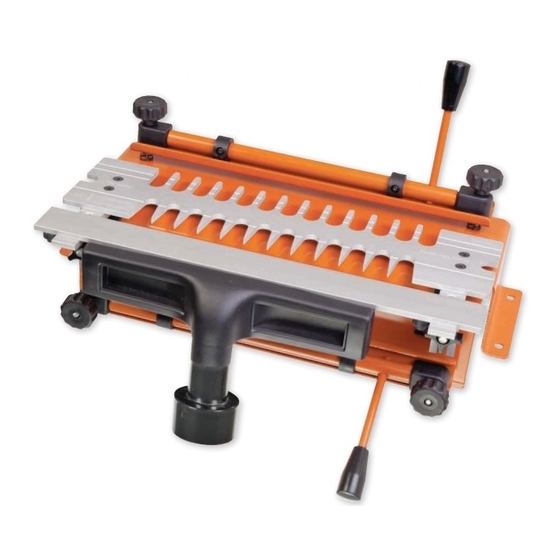
Page 8: Illustration And Parts Description
Illustration and Parts Description Horizontal Clamp bar handle Pressure adjustment knob Dovetail mounting bracket Horizontal cam bar Clamp bar Pressure adjustment knob Extraction outlet Vertical cam bar Router cutter depth stop... - Page 9 Illustration and Parts Description Guide bush Dovetail joint guide securing Hex screws Vertical cam clamps (A) and clamp bar (B) Horizontal cam clamps (A) and clamp bar (B) Router cutter depth adjuster (Pin Depth) Outer clamping star knob (A) Inner brass depth wheel (B)
- Page 10 Illustration and Parts Description Horizontal clamping bar assembly Clamping bar plate Support plate for extraction outlet Dovetail joint guide Dovetail jig rear view Mounting bracket holes Vertical pressure adjustment knob Side stop cap screw (A) Side stop (B)
-
Page 11: Dovetail Jig Set-Up
Dovetail Jig Set-up Mounting the Jig Router Cutter Mount the jig onto a firm and stable workbench at a Supplied with three 1/4” shank cutters, (7˚dovtail/ comfortable height,remembering that the router sits on straight), see fig C. You can also purchase 8mm or 1/2” top of the jig. -
Page 12: Ujk Dovetail Jig Processes
UJK Dovetail Jig Processes Fig 05 (Chapter 0.1) Process for Through Dovetail Cut Tails First 1. Select the through dovetail and finger joint comb, (E). Bolt this onto the comb bar support brackets (B) using 3. To help set up the cutter depth it is worth using a the four countersunk hex screws (J) making sure that cutting gauge. - Page 13 UJK Dovetail Jig Processes 6. Clamp these boards in place using the eccentric bar Fig 09 clamps, the pressure of the eccentric bar clamps being adjusted by turning the plastic knobs mounted at each end of the eccentric bar clamps, see page 8. When adjusting these ensure that the eccentric bar is paralleled to the jointing face of the jig, the aim being to hold the board firmly.
- Page 14 UJK Dovetail Jig Processes Screw together the guide bush and fixing ring, fix this Setting the Cutter Height to the base of the router, with the flange section facing 12. With the router still unplugged, carefully position the downwards out of the bottom of the router, this will run router on the jig.
- Page 15 UJK Dovetail Jig Processes router. Sit the router on the jig so that the cutter goes Setting the Cutter Height for ‘Pin’ Boards between and will be supported by the template comb 16. Unplug the router. On the left hand side of the jig and extraction bar.
- Page 16 UJK Dovetail Jig Processes 21. On the face of the template is one preset line that Setting up jig for the ‘Pin’ boards runs across the comb, this needs to line up with the 18. Remove the four countersunk hex screws and turn back face of the position ‘Pin’...
- Page 17 UJK Dovetail Jig Processes 24. Remove the now routed parts from the jig and test fit Fig 30 these together, any adjustment on how tight the joint fits together can now be made to the ‘Pin’ board. If the joint is too tight to go together, this can be adjusted by moving the comb bar location towards the back of the jig, this being done by moving the brass adjustment wheel clockwise, see fig 34, how much will depend on...
-
Page 18: (Chapter 0.2) Process For Lapped/Half Blind Dovetail
UJK Dovetail Jig Processes (Chapter 0.2) Collet Process for Lapped/Half Blind Dovetail Cutter shank Visual mark 1. Select the aluminum comb which has a cut out on one side only and fix onto jig frame, with the cut out facing the front, see fig 37. - Page 19 UJK Dovetail Jig Processes 4. Having loaded the horizontal board, clamp this in a gap between the meeting edges. Ensure these meet place check that the comb bar is sat level upon the squarely and are level on the jointing surface, test with a workpiece.
- Page 20 UJK Dovetail Jig Processes cutter. This will need to be set up and tested on wood first. With this being a single pass operation the cutter depth is set to one height and cannot be changed, even if the material thickness changes, the cutter depth is still set the same, mark a scribe line of 11mm on the end of the vertical board, as in fig 46 and 47 on page 19, with the router unplugged from the mains, position the router...
- Page 21 UJK Dovetail Jig Processes 17. With the comb bar is removed it shows the two Fig 52 boards held in the jig having been cut in the offset position, see fig 54-55. Fig 54-55 aim being to create a small cut line along the face of the board, see diagram below.
- Page 22 UJK Dovetail Jig Processes If the (draw) side material projects from the (draw) If the (draw) front material over hangs the (draw) side front, see fig 56. material, see fig 57 To get this level adjust the comb bar, by moving this To get this level undo the black star locking knobs and towards the back of the jig, away from the user.
-
Page 23: (Chapter 0.3) Process For Finger/Box Joint
UJK Dovetail Jig Processes 3. Both parts of this joint are cut in the vertical position (Chapter 0.3) within the jig, the comb will need to be set-up in the Process for Finger/Box Joint position of which these will be cut for each part of the joint. - Page 24 UJK Dovetail Jig Processes 6. To set the cutter depth on the router, this is best 10. Reposition the extraction support bar, due to that done using a marking gauge. Cut a scribe line across fact that this cut uses a straight cutter it is possible to the board, the marking gauge being set to the thickness cut in more than one pass if using very hard material.
- Page 25 UJK Dovetail Jig Processes 12. To set up the comb for the opposite part of this 14. Position the other board within the vertical position joint. Using the board that has just been cut, (board in of the jig, ensure that this lies parallel to the side stop vertical position within the jig) release this from the cam and also meets squarely on the underside of the comb lock pressure by pulling the locking handle up.
-
Page 26: Exploded Diagram/Parts List
Exploded Diagram/Parts List... - Page 27 Exploded Diagram/Parts List No Part No Description D235014000011Z SLIDING NUT DJA1-17 LOCK KNOB DJA1-9B BASE E0811060033D SPRING WASHER 4212-21 SPRING A211014038031D SCREW DJA1-14B CLAMP BAR DJA1-7 DUST COLLECTOR 4212-17 CLAMP ROD BLOCK DJA1-6 REDUCER H211014000011Z KNOB DJA1-3 TEMPLATE BRACKET 4212-16 CLAMP ROD CAM A108005010011Z SCREW...
- Page 28 The UJK technology brand was launched by Axminster in 2012 with the intention of encompassing a range of carefully selected products that Axminster held in particular high esteem. Many of these products are designed by and manufactured by Axminster. The range includes routing, measuring and wood jointing products and has proven to be extremely popular.
Need help?
Do you have a question about the 506300 and is the answer not in the manual?
Questions and answers