
Related Manuals for Danfoss ADAP-KOOL AK-PC 572


Summary of Contents for Danfoss ADAP-KOOL AK-PC 572
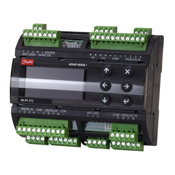
- Page 1 User Guide Capacity controller for CO 2 mini pack AK-PC 572 ADAP-KOOL® Refrigeration Control System...
-
Page 2: Operation
In order to control the high pressure valve and receiver pressure valve, two valve driver modules, type EXD 316, must be con- nected. The overview of connections can be seen on page 22. User Guide RS8KH202 © Danfoss 2019-03 AK-PC 572... -
Page 3: Suction Group
If the output is available, the controller can pulse oil into the MT circuit. The time between the pulses can be configured using a timer function or using a signal from a level switch. AK-PC 572 User Guide RS8KH202 © Danfoss 2019-03... - Page 4 The pressure reference will be the configured value for the sub- cooling when adjusting in the sub-critical range, and will be ad- justed based on optimal COP when adjusting in the trans-critical range. The reference value will be user-configured during heat recovery. User Guide RS8KH202 © Danfoss 2019-03 AK-PC 572...
-
Page 5: Receiver Control
This function allows for hot gas to be passed to the receiver if the pressure approaches Po-MT. Hot gas will be shut off again when the pressure returns above the desired level. AK-PC 572 User Guide RS8KH202 © Danfoss 2019-03... - Page 6 • A "Fan error" that will be shown in the display and in the system unit if it occurs. • A text alarm that will be shown in the display and in the system unit if it occurs. User Guide RS8KH202 © Danfoss 2019-03 AK-PC 572...
-
Page 7: Safety Functions
(UPS) for both the controller and the valve to avoid faults. A relay in the UPS should be incorporated into the controllers safety circuit so that it can restart safely. AK-PC 572 User Guide RS8KH202 © Danfoss 2019-03... -
Page 8: Display Overview
When an alarm is sent from the con- troller, you must advance to this display to see the alarm text. Then click on the alarm text to view the details relating to the alarm. User Guide RS8KH202 © Danfoss 2019-03 AK-PC 572... -
Page 9: Setup Overview
When the Plant type has been selected, it will al- low several settings to be made. For example: Continue to the next menus. All settings are explained on the pages that follow. AK-PC 572 User Guide RS8KH202 © Danfoss 2019-03... - Page 10 An offset can originate from a night increase signal or from an override function on the Fab: -10°C system device. PI control selection Set how quickly the PI regulation must react here: 1 = slowly, 10 = very quickly. Min: 1 Max: 10 Fab: 5 User Guide RS8KH202 © Danfoss 2019-03 AK-PC 572...
- Page 11 Min. period of time for restarting remaining compressors Min: 1 min. Max: 60 min Set the forced On+Off-time before it can be switched on again. The setting is to prevent Fac: 5 min incorrect operation. AK-PC 572 User Guide RS8KH202 © Danfoss 2019-03...
- Page 12 The regulation is normally set to “Auto”, but it can be changed to “Manual”. Vhp manual capacity When setting to “Manual”, capacity can then be forced set in %. Min: 0 % Max: 100% User Guide RS8KH202 © Danfoss 2019-03 AK-PC 572...
-
Page 13: Fan Configuration
Here you can see how many hours the fans have been operational for since the last reset EC Cycl. total Here you can see how many fan starts there have been since the last reset AK-PC 572 User Guide RS8KH202 © Danfoss 2019-03... -
Page 14: Oil Control
Max: 20 K (Superheating is measured in the suction line by PoMT and SsMT.) Fac: 4 K Superheat Max. MT Alarm limit for excess superheating Min: 20 K Max: 80 K Fac: 50 K User Guide RS8KH202 © Danfoss 2019-03 AK-PC 572... -
Page 15: Aux. Functions
You can choose between the following functions: Liquid injection, DE-SH or hot gas dumping DO AUX3 Relay output in the receiver module DO-demand You can choose between the following functions: Liquid injection, DE-SH or hot gas dumping AK-PC 572 User Guide RS8KH202 © Danfoss 2019-03... - Page 16 (!). In this case, you must either activate the function in the configu- ration, or deselect the function on the input or output in question. User Guide RS8KH202 © Danfoss 2019-03 AK-PC 572...
- Page 17 Digital input Here you can see the status of the function/alarm. Status of analogue outputs Analog output Here you can see the size of the output signals as a % of max. signal. AK-PC 572 User Guide RS8KH202 © Danfoss 2019-03...
- Page 18 Factory setting for the alarm can be seen on page 19. High Sd temperature Compressor safety: Suction group LT Low pressure: High pressure: Superheat High Sd temperature Compressor safety: Fan safety: HP control: User Guide RS8KH202 © Danfoss 2019-03 AK-PC 572...
-
Page 19: Alarm List
If you have corrected the sensor error and want to perform a manual, forced removal of the alarm, go to the “Alarm detail display” Press and hold the “X” key for 2 seconds here. AK-PC 572 User Guide RS8KH202 © Danfoss 2019-03... - Page 20 9. Press the X key to return to the Bios menu 10. Select the “Application” menu and press Enter. The display will once again retrieve data from the controller. This process will take about 5 minutes. User Guide RS8KH202 © Danfoss 2019-03 AK-PC 572...
- Page 21 The two 1-digits represent the addresses 96 and 97 respec- The addresses will only be used internally between the three tively. modules. If you remove the connection to a valve module, the display of the address will also disappear. AK-PC 572 User Guide RS8KH202 © Danfoss 2019-03...
- Page 22 Connections User Guide RS8KH202 © Danfoss 2019-03 AK-PC 572...
- Page 23 The alarm relay will be driven under normal operation and will drop in the event of alarms and insufficient voltage to the controller. (DO3 can be used as an AUX1 output, but only if regulated with 2 MT compressors). AK-PC 572 User Guide RS8KH202 © Danfoss 2019-03...
- Page 24 If an external display is connected, it must be connected to the controller using a wire with a plug. See order. Communication will take place via Canbus. The Canbus termination must be moved away from the controller and to the external display. User Guide RS8KH202 © Danfoss 2019-03 AK-PC 572...
- Page 25 Alternatively, wiring must be created using the compressor relays. When all compressors have been stopped, a signal must be is- sued to the evaporator controls that will subsequently close the expansion valves. AK-PC 572 User Guide RS8KH202 © Danfoss 2019-03...
- Page 26 8 analog Input 4-20 mA good engineering practice. Temperature measurement Danfoss will not be responsible for any goods, or plant compo- Pt 1000 ohm/0°C nents, damaged as a result of the above defects. It is the installer's From contact function responsibility to check the installation thoroughly, and to fit the E.g.
-
Page 27: List Of Literature
L = 3 m, 1 pcs List of literature Installation guide for extended operation RC8AC Here you can see how a data communication connection to ADAP-KOOL® Refrigeration control systems can be established. AK-PC 572 User Guide RS8KH202 © Danfoss 2019-03... - Page 28 Danfoss påtager sig intet ansvar for mulige fejl i kataloger, brochurer og andet trykt materiale. Danfoss forbeholder sig ret til uden forudgående varsel at foretage ændringer i sine produkter, herunder i produkter, som allerede er i ordre, såfremt dette kan ske uden at ændre allerede aftalte specifikationer.
Need help?
Do you have a question about the ADAP-KOOL AK-PC 572 and is the answer not in the manual?
Questions and answers