
Related Manuals for Motorola APX 6000XE 2.5


Summary of Contents for Motorola APX 6000XE 2.5
- Page 1 Butler Regional Interoperable Communications System RADIO AND SYSTEM ORIENTATION APX 6000XE Model 2.5...
- Page 2 UNDERSTANDING THE NUMBERS • PSAPs match the fire agency and station numbering • Engine 61 is dispatched by 6COM (Monroe) • LE agencies match too (like Fairfield Township as 21, Ross as 10, and Seven Mile as 17)
-
Page 3: Radio Controls
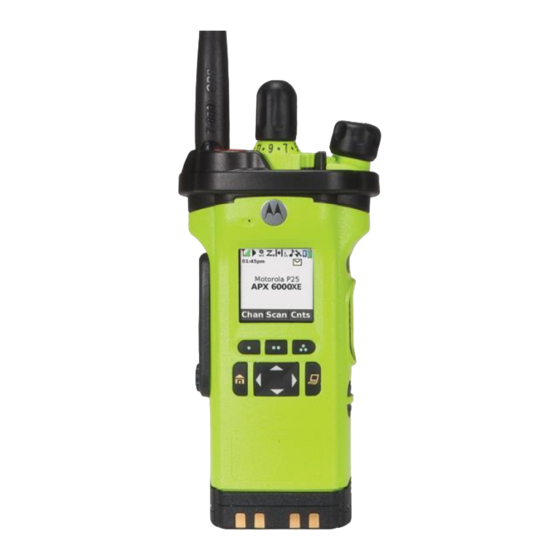
Butler Regional Interoperable Communications System RADIO CONTROLS APX 6000XE Model 2.5... - Page 4 RADIO CONTROLS Antenna 16-Position Select Knob* On/Off/Volume Control Knob Zone Select Microphone Main Display Menu Select Buttons 4-Way Navigation Button *Future Usage Home Button * These radio controls/buttons are programmable.
- Page 5 RADIO CONTROLS Antenna 16-Position Talkgroup Knob On/Off/Volume Control Knob Display Microphone Channel Main Speaker Announcement Push-to-Talk (PTT) Button Light/Flip Battery Site/Dspl Battery Latch...
- Page 6 RADIO CONTROLS 3 Position 16-Position Zone Select Talkgroup Knob Switch On/Off/Volume Control Knob EMERGENCY Antenna Top Display SCAN ON = OFF =...
-
Page 7: Preparing Your Radio For Use
PREPARING YOUR RADIO FOR USE Attaching/Removing the Battery With the radio turned off, slide the battery into the radio’s frame until side latches click into place. To remove the battery, turn the radio off. Squeeze the release latches at the bottom of the battery until the battery releases from the radio. - Page 8 PREPARING YOUR RADIO FOR USE Antenna Note: Frequently check the antenna to ensure that it is tight. Antenna ONLY USE THE ANTENNA SUPPLIED WITH THE RADIO...
- Page 9 PREPARING YOUR RADIO FOR USE Attaching/Removing the Accessory Connector Cover The accessory connector is located on the antenna side of the radio. It is used to connect accessories to the radio. Note: This is an area where moisture accumulates. Occasionally remove your accessory to clean this area.
- Page 10 Position the radio within the holster with the main strap and pull the radio out using the plastic lip with the speaker facing outward and the LCD display facing the Motorola logo on it. Do not pull the radio out by the belt clip antenna!
- Page 11 PREPARING YOUR RADIO FOR USE Using the Plastic Carry Holder To remove the radio from the carry holder, place the tip of Position the radio within the your fingers on the ledge of the carry holder and push at the carry holder with the main bottom of the radio until the radio is released from it.
-
Page 12: Turning On/Off The Radio
PREPARING YOUR RADIO FOR USE Turning on/off the Radio Rotate the On/Off/Volume Control Knob clockwise until you hear a click. If the power-up test is successful, you see SELFTEST on the On/Off/Volume radio’s display momentarily, followed by the home screen. Control Knob Note: If the power-up test is unsuccessful, turn radio off and back on to see if it is successful. -
Page 13: Adjusting The Volume
PREPARING YOUR RADIO FOR USE Adjusting the Volume To increase the volume, turn the On/Off/Volume Control Knob clockwise. To decrease the volume, turn this knob counterclockwise. On/Off/Volume Note: Ensure that the main speaker is pointed towards you Control Knob for increased loudness and intelligibility, especially in areas with loud background noises. -
Page 14: General Operation
Butler Regional Interoperable Communications System GENERAL OPERATION APX 6000XE Model 2.5... -
Page 15: Push-To-Talk (Ptt) Button
IDENTIFYING RADIO CONTROLS Push-To-Talk (PTT) Button • Press and hold down PTT button, wait for the talk permit tone, then talk. Release the PTT button to listen. The microphone is activated when the PTT button is pressed. • While a call is not in progress, the PTT button is used to make a new call. - Page 16 MICROPHONES Speak Clearly into the microphone Red Lines indicate microphones...
-
Page 17: Accessing The Preprogrammed Functions
IDENTIFYING RADIO CONTROLS Accessing the Preprogrammed Functions You can access various radio functions through one of the following ways: • A short or long press of the relevant programmable buttons. • Use the Menu Select Buttons ( Using the Menu Select Buttons The Menu Select Buttons allow to access the menu entries of features. - Page 18 IDENTIFYING RADIO CONTROLS Using the Navigation Buttons Home Button button returns you to you Zone A, Channel 1. In most cases, this is the current mode. For selected radio features, the button is also used to save user-edited radio settings or information before returning you to the home screen.
-
Page 19: Status Icons
IDENTIFYING STATUS INDICATORS Status Icons The 130 x 130 pixel front liquid crystal display (LCD) of your Received Signal Strength Indicator (RSSI) The number of bars displayed represents the received radio shows radio status, text entries, and menu entries. The signal strength for the current site, for trunking only. - Page 20 IDENTIFYING STATUS INDICATORS Secure Operation Bluetooth On • On = Secure operation. Bluetooth is on and ready for Bluetooth connection. • Off = Clear operation. • Blinking = Receiving an encrypted voice call. Bluetooth Connected Location Signal Bluetooth is currently connected to the external Bluetooth •...
-
Page 21: Led Indicator
IDENTIFYING STATUS INDICATORS LED Indicator The LED indicator shows the operational status of your radio. - Page 22 IDENTIFYING STATUS INDICATORS – Solid red Radio is transmitting in trunked mode. – Blinking red Radio is transmitting at low battery condition. – Double blinking red Radio is in Emergency Mode. – Rapidly blinking red Radio has failed the self test upon powering up or encountered a fatal error. –...
- Page 23 IDENTIFYING STATUS INDICATORS Orange Green Emergency Alerts Critical Alerts Call Alerts...
-
Page 24: Intelligent Lighting Indicators
IDENTIFYING STATUS INDICATORS Intelligent Lighting Indicators This feature temporary changes the radio’s display backlight color and the alert text background color to help signal that a radio event has occurred. Note: This feature must be preprogrammed by a qualified radio technician. Backlight and Bar Color Notification When... -
Page 25: Alert Tones
IDENTIFYING STATUS INDICATORS Alert Tones Your radio uses alert tones to inform you of your radio’s condition. The following table lists these tones and when they occur. You Hear Tone Name Heard Short, Radio Self Test Fail When radio fails its power-up self test. Low-Pitched Reject When unauthorized request is made. - Page 26 IDENTIFYING STATUS INDICATORS You Hear Tone Name Heard Short, Valid Key-Press When correct key is pressed. Medium-Pitched Radio Self Test Pass When radio passes its power-up self test. Tone Clear Voice At beginning of a non-coded communication. Priority Channel Received When activity on a priority channel is received.
- Page 27 IDENTIFYING STATUS INDICATORS You Hear Tone Name Heard Two High-Pitched Tones GPS Fails When the GPS signal is lost or when GPS fails. Ringing Fast Ringing When system is searching for target of Private Call. Enhanced Call Sent When waiting for target of Private Call to answer the call. Phone Call Received When a land-to-mobile phone call is received.
-
Page 28: General Radio Operation
GENERAL RADIO OPERATION Selecting a Zone A zone is a group of talkgroups. Procedure: [Zone (3-Position A/B/C)] 1. Move the preprogrammed Zone (3-Position A/B/C) switch to the position of the required zone. [Menu] to Zone. 2. Press the Menu Select button directly below Zone. to the required zone. -
Page 29: Selecting A Radio Channel
GENERAL RADIO OPERATION Selecting a Radio Channel A channel is a group of radio characteristics, such as transmit/receive frequency pairs. Procedure: [16-Position Select Knob] 1. Turn the preprogrammed 16-Position Select Knob to the desired channel. [Menu] to Chan. 2. Press the Menu Select button directly below Chan. to the required channel. - Page 30 RADIO TEMPLATE LOCAL A,B,C Switch A LAW B TAC C HELP Name E C F S Name E C F S Name E C F S 09 XXXX 09 XXXX 09 HELP 09 INQUIRY 1 09 EVNT 02 T A 09 TALK 09 DESK 1 09 EVNT 03 T A...
- Page 31 9COM MAIN LE TALKGROUPS 09 ZULU / “Nine Zulu” • Zone A – 1 • 9COM law enforcement dispatching – for all agencies except HPD, OPD, OTPD and FTPD • All BCSO users 09 DELTA / “Nine Delta” • Oxford PD, OTPD •...
- Page 32 BRICS AND MARCS Local Sites (BRICS) Primary Dispatch Channels Adjacent (BRICS + MARCS) Incident Channels Statewide (BRICS + MARCS) Travel Channel...
- Page 33 ZONE A Top of Zone A 09 INQUIRY Inquiry dispatcher 09 DESK Zone A All 9COM Law Enf. 09-XXXX Hamilton and Oxford desk 09 INQUIRY Normally patched to 09 09 DESK INQUIRY 09-XX WIDE A4 WIDE Local use channel A-1 is different A2 through A3 are the same A2 –...
- Page 34 THE LAW TALKGROUPS Zone A – Channels 5 through 13, 16 • Shared by all law enforcement Adjacent Butler Co Encrypted Zone A • Assigned by the dispatch centers 09-XXXX 09-9L INQR • Encrypted channels 09 DESK 09 SO WIDE •...
- Page 35 THE PURSUIT TALKGROUPS Zone A – Channels 14 through 15 • Shared by all law enforcement the state Zone A 09-XXXX • Future usage 09-9L INQR • Training will be provided when 09-9L OPS3 09-9P OPS4 finalized 09 LAW 05 •...
- Page 36 THE TAC TALKGROUPS Zone B – Channels 5 through 16 • Shared by all law, fire and EMS Adjacent Butler Co Encrypted • Assigned by the dispatch centers Zone B 09 XXXX • Encrypted channels 09 EVNT 02 09 EVNT 03 •...
- Page 37 NINE TRAVEL 09-X TRVL (“Travel”) Statewide Travel talkgroup Zone C – 3 Statewide • In all radios Why it’s good: Not Encrypted • Allows you to talk with • Lets you call dispatch • Lets dispatch call you your dispatch center •...
- Page 38 JAIL CALL Calling Patrol Jail 09 J-CALL • “Jail Call” • Need the sallyport • Monitored by BC jail opened? control room • Need to reach the jail • Zone C-10 for all law control room for any enforcement agencies reason? •...
- Page 39 RADIO TEMPLATE LOCAL ZONE Using Soft Keys (ZONE) D MA D1 MA D2 MA E HOSP F FIRE G LAW Zone Z Name E C F S Name E C F S Name E C F S Name E C F S Name E C F S Name...
- Page 40 RADIO TEMPLATE (GLOBAL)
- Page 41 THE CVRT TALKGROUPS Zone Z – Channels 5 through 12 • Law Enforcement only, for: Adjacent • SWAT, surveillance, Encrypted covert operations, BURN Zone Z 09 XXXX assists 09 INQUIRY • Assigned by the dispatch 09 DESK 09-XX WIDE centers, but they are not on 09 CVRT 05 the dispatchers’...
- Page 42 RADIO TEMPLATE (CONTD.) HAMILTON COUNTY, PREBLE COUNTY Using Soft Keys (ZONE) Hamilton County / Cincinnati System MARCS 348 Preble County H1 Hamilton H2 Hamilton Cincinnati H4 Hamilton H5 Hamilton I Preble Name E C F S Name E C F S Name E C F S Name...
- Page 43 RADIO TEMPLATE (CONTD.) MONTGOMERY COUNTY Using Soft Keys (ZONE) Montgomery County MARCS 348 K1 Montgomery K2 Montgomery K5 Montgomery Name E C F S Name E C F S Name E C F S 57 LE 1 2 57 RDC NORTH T 57 CW 1 57 LE 2 2 57 RDC SOUTH T...
- Page 44 RADIO TEMPLATE (CONTD.) WARREN COUNTY, SW TAC Using Soft Keys (ZONE) L1 Warren L2 Warren M0 SW TAC M1 SW TAC Name E C F S Name E C F S Name E C F S Name E C F S 83PD PRIM1 R 4 83PD PRIM 1 R SW TAC 1...
- Page 45 RADIO TEMPLATE (CONTD.) STATEWIDE INTEROPERABILITY Using Soft Keys (ZONE) M2 LECOM M3 MARCS M4 ECOMM M5 ECOMM M6 SO M7 PURSUIT Name E C F S Name E C F S Name E C F S Name E C F S Name E C F S Name...
- Page 46 RADIO TEMPLATE (CONTD.) TOWER ON WHEELS Using Soft Keys (ZONE) MARCS 5A1 MARCS 649 M8 TOW 5A1 M9 TOW 649 Name E C F S Name E C F S XSCOMM01 T 6 XSCOMM17 T XSCOMM02 T 6 XSCOMM18 T XSCOMM03 T 6 XSCOMM19 T XSCOMM04 T...
- Page 47 RADIO TEMPLATE (CONTD.) TRAINING Using Soft Keys (ZONE) E BUTTON This is a zone that allows training on usage or general radio training BRICS TRAINING TRAINING Name E C F S 09TRN TCTL 09TRN TCT2 09TRN TCT3 09TRN REV4 09TRN REV5 09TRN HOTT 09TRN HOTR...
- Page 48 RADIO TEMPLATE (CONTD.) 700MHz Conventional Using Soft Keys (ZONE) 700MHz Conventional V Nat Mut Aid W Nat Mut Aid X Nat Mut Aid Y Nat Mut Aid Name E C F S Name E C F S Name E C F S Name E C F S 7 CALL 50...
- Page 49 SCANNING LE LE at Other PSAPs G LAW 3COM: Fairfield Name 4COM: Miami University 5COM: Trenton 09-3L MAIN 6COM: Monroe 09-4L MAIN 7COM: West Chester 09-5L MAIN 8COM: Middletown 9COM: Butler County 09-6L MAIN Zone G 09-7L MAIN •...
- Page 50 SCANNING FD FD at Other PSAPs 3COM: Fairfield F FIRE 4COM: Miami University Name 5COM: Trenton 09-3F MAIN 6COM: Monroe 09-5F MAIN 7COM: West Chester 09-6F MAIN 8COM: Middletown 09-7F MAIN 9COM: Butler County ...
- Page 51 9COM FIRE CHANNELS 09 ALPHA / “Nine Alpha” 09 BRAVO / “Nine Bravo” • Zone F (for scanning) • Zone F (for scanning) • 9COM fire / EMS • 9COM fire / EMS dispatching – West side dispatching for Hamilton departments FD, Liberty Twp FD and Fairfield Twp FD.
- Page 52 ALL-COUNTY BROADCAST The All-County Broadcast (ACB) • Hear ACBs from any Butler 09 LE INFO / 09-31 ACB County dispatch center • Keep it in your scan list! • 09-31 ACB • It’s in Zone G • Can hear Hamilton •...
-
Page 53: Advanced Features
Butler Regional Interoperable Communications System ADVANCED FEATURES APX 6000XE Model 2.5... - Page 54 ADVANCED FEATURES Scan Turning Scan On or Off This feature allows you to monitor traffic on different channels by scanning a preprogrammed list of channels. Procedure: [Preprogrammed Button] 1. Press the preprogrammed Scan button, or turn the preprogrammed Scan switch to the Scan on or Scan off position, to initiate or stop scan.
-
Page 55: Scan Lists
ADVANCED FEATURES Scan Lists Viewing a Scan List Scan lists are created and assigned to individual channels/groups. Your radio scans for voice activity by cycling through the channel/group sequence specified in the scan list for the current channel/group. Procedure: to ScnL. - Page 56 ADVANCED FEATURES Scan Lists Editing the Scan List This feature lets you change scan list members and priorities. Procedure: Press the Menu Select button directly below Rcl to view the next member of the scan list. [Menu] to ScnL. to select more channels to be added or deleted.
- Page 57 ADVANCED FEATURES Priority Status Below the Sel, Del, and Rcl screen, press the Menu Select button directly below Sel to view and/or change the priority status of the currently displayed channel. Below the Sel, Del, and Rcl screen, press the Sel button one or more times to view and/or change the scan list status icon of the currently displayed channel.
-
Page 58: Deleting A Nuisance Channel
ADVANCED FEATURES Scan Deleting a Nuisance Channel If a channel continually generates unwanted calls or noise The 16-Position (termed a “nuisance” channel), you can temporarily remove Talkgroup the unwanted channel from the scan list. Select Knob This capability does not apply to priority channels or the On/Off/Volume designated transmit channel. -
Page 59: Restoring A Nuisance Channel
ADVANCED FEATURES Scan Restoring a Nuisance Channel Procedure: Emergency Button The 16-Position Talkgroup To restore the deleted nuisance channel, do one of the Select Knob following: On/Off/Volume • Turn the radio off and then turning it on again. Control Knob •... -
Page 60: Emergency Operation
ADVANCED FEATURES Emergency Operation The Emergency feature is used to indicate a critical situation. Note: The radio operates in the normal dispatch manner while in Emergency Call, except if enabled, it returns to one If the Top (Orange) button is preprogrammed to send an of the following: emergency signal, this signal overrides any other •... - Page 61 ADVANCED FEATURES Emergency Operation • You will be queried by a dispatch center about your activation. The 16-Position On/Off/Volume Select Channel Control Knob • EX: 9COM to 1S38, Are you declaring an Knob * emergency? Top (Orange) • If this is an actual emergent activation, simply button * state your emergency and the resources needed.
-
Page 62: Global Positioning System/ Global Navigation Satellite System
ADVANCED FEATURES Global Positioning System/ Global Navigation Satellite System The Global Navigation System (GNSS) in the radio integrated the information from the Global Positioning System (GPS) and Global Navigation Satellite System (GLONASS) to determine the approximate geographical location of your radio. Note: This feature is addressed as GPS across the manual as the naming convention of the buttons and strings remain the same as the legacy feature of GPS. -
Page 63: Gps Operation
ADVANCED FEATURES Global Positioning System/ Global Navigation Satellite System GPS Operation The GPS technology uses radio signals from earth orbiting satellites, to establish the location coordinates, maximizing your view of clear unobstructed sky is essential for optimum performance. Where adequate signals from multiple satellites are not available (usually because you cannot establish a view of a wide area of the sky), the GPS feature of your radio will not work. -
Page 64: Trunking System Controls
ADVANCED FEATURES Trunking System Controls Out-of-Range Radio When your radio goes out of the range of the system, it can On/Off/Volume no longer lock onto a control channel. The 16-Position Control Knob Talkgroup Select Procedure: Top (Orange) 1. You hear a low-pitched tone. button * AND/OR The display shows the currently selected zone/channel... -
Page 65: Site Trunking Feature
ADVANCED FEATURES Trunking System Controls Site Trunking Feature If the zone controller loses communication with any site, that site reverts to site trunking. The display shows the currently selected zone/channel Model 2 combination and Site trunking. What does it mean when my radio says “SITE TRUNKING?”... - Page 66 ADVANCED FEATURES Turning Bluetooth Visibility On Receiving Pairing Request from other Devices Turning Bluetooth visibility to on enables other Bluetooth devices to search for your radio. Procedure: The visibility of the Bluetooth is set to off by default. 1. When your radio receives a pairing request from other device, the display shows <Device Friendly Name>...
- Page 67 ADVANCED FEATURES Searching and Pairing a Bluetooth Device The BT Searching screen shows the name of Bluetooth devices found if there are any. Bluetooth Search in Bluetooth Standard Pairing method is used to scan for other Bluetooth devices nearby. It is set to To stop the searching press the Menu Select button Off by default.
-
Page 68: Over-The-Air Programming (Pop 25, Astro 25, Astro Conventional, And Wi-Fi)
ADVANCED FEATURES Over-the-Air Programming (POP 25, ASTRO 25, ASTRO Conventional, and Wi-Fi) This feature enables configuration data and firmware to be upgraded to your radio over-the-air. Full use of the radio is retained during the data transfer without interrupting communication. For ASTRO 25 and ASTRO Conventional, the upgrade pauses to give priorities to voice call, and continues after the voice call ended. -
Page 69: Responding To The Notification Of Upgrade
ADVANCED FEATURES Over-the-Air Programming (POP 25, ASTRO 25, ASTRO Conventional, and Wi-Fi) Responding to the notification of Upgrade Procedure: 1. The display shows Upgrade?. Press the Menu Select button below Acpt to accept the request to upgrade immediately. The display shows Upg Rx In Prog to indicate the upgrade received is in progress. Press the Menu Select button below Dlay to delay the request to upgrade. - Page 70 ADVANCED FEATURES Wi-Fi Turning Wi-Fi On or Off This feature allows you to turn Wi-Fi on or off. Wi-Fi can be used for wireless programming of the radio with the Radio Management tool. Note: Wi-Fi should be left off unless BRICS Note: Wi-Fi Network Name (SSID) for the radio to connect to instructs you to turn it on.
- Page 71 ADVANCED FEATURES Wi-Fi Checking the Wi-Fi Configuration and Status of the Radio Procedure: The display shows the current status of the Wi-Fi as described next. [Menu] to Wi-Fi. Searching Looking for available Wi-Fi networks that have been preprogrammed into the radio. 2.
- Page 72 Butler Regional Interoperable Communications System UTILITIES APX 6000XE Model 2.5...
-
Page 73: Using The Flip Display
UTILITIES Using the Flip Display This feature allows you to flip the content of the top display upside down. It is particularly useful when you would like to read the top display while the radio is still in the carry holder attached to your belt. -
Page 74: Selecting A Radio Profile
UTILITIES Selecting a Radio Profile This feature allows you to manually switch the visual and Procedure: audio settings of the radio. The display, backlight, alert tones, and audio settings are defined according to the [Menu] preprogrammed radio settings of each radio profile. to Prfl. -
Page 75: Turning Keypad Tones On Or Off
UTILITIES Turning Keypad Tones On or Off You can enable and disable keypad tones, if needed. Top (Orange) The 16-Position Button* Talkgroup Select Procedure: On/Off/Volume [Menu] Control Knob to Mute. 2. Press the Menu Select button directly below Mute. The display momentarily shows Tones off, indicating that Top Side the keypad tones are disabled. -
Page 76: Time-Out Timer
UTILITIES Time-Out Timer This feature turns off your radio’s transmitter. You cannot transmit longer than the preset timer setting. If you attempt to do so, the radio automatically stops your transmission, and you hear a talk-prohibit tone. The timer is defaulted at 60 seconds. Note: You will hear a brief, low-pitched, warning tone four seconds before the transmission times out. -
Page 77: Impres Battery Annunciator
UTILITIES IMPRES Battery Annunciator This feature displays the current capacity and charges cycles To access battery info screen: of your battery when a IMPRES Battery is powering your radio. Procedure: This feature must be enabled in your radio to see the to Batt. - Page 78 Butler Regional Interoperable Communications System CHARGING AND MAINTENANCE APX 6000XE Model 2.5...
- Page 79 CHARGING Motorola Impress® Smart Charger Recharge after each shift. This “smart” charger will: • Monitor usage patterns • Store that information in the battery • Recondition the battery when needed • Not overheat regardless of how long it’s left in...
- Page 80 CHARGING Charger Lights Charge Indicator Description Steady Battery is in rapid charge mode. Label on Blinking Green Battery has completed rapid charge (>90% available capacity). the side Battery is in Top-Off charge (Trickle Charge) and requires of the approximately 1 hour. charger Steady Green...
-
Page 81: Online Help
ONLINE HELP... -
Page 82: Radio Problems
TROUBLESHOOTING AND REPAIR Radio Problems If your radio is not working or broken, bring it to us! http://brics.butlersheriff.org/ 513-785-1299...
Need help?
Do you have a question about the APX 6000XE 2.5 and is the answer not in the manual?
Questions and answers