Table of Contents
Advertisement
Quick Links
ITEMS INCLUDED (GENERATION 1 & 2):
•
Fan assembly with electrical control box
•
Chain (25 ft.)
•
Duct tape (30 ft.)
•
7 ft. of acoustic fl ex duct (16" diameter)
•
Backdraft Damper; Backdraft Damper Transition
Cone; and, ¼" Phillips head screws (12)
•
White cube core grille & White phillips head screws
(8)
•
Wood screws (8)
•
Self-tapping sheet metal screws (4)
•
S-Hooks (4)
•
Control Package, including: Control box; Wall
Controller Switch with Mounting Bracket; and Red
CAT-5 cable (50 ft.)
This device MUST be installed by a qualifi ed agency in accordance with the manufacturer's installation instructions. The defi nition of
a qualifi ed agency is: any individual, fi rm, corporation or company which either in person or through a representative is engaged
in, and is responsible for, the installation and operation of HVAC appliances, who is experienced in such work, familiar with all the
precautions required, and has complied with all the requirements of the authority having jurisdiction.
Installed By:
INSTALLATION MANUAL
VentCool™ 1.8
WHOLE HOUSE FAN
Please retain these instructions after installation.
Phone:
www.fi eldcontrols.com
SUPPLIES NOT INCLUDED & REQUIRED TOOLS:
•
Phillips head screw driver
•
Scissors or Knife
•
Pliers
•
Drywall Cutter
•
Cordless screwdriver with Phillips head and mis-
cellaneous drill bits
•
High quality latex caulk
•
Lumber matching dimensions of the attic joists
(e.g. 2"x6", 2"x8", etc.) and cut to fi t according to
the INSTALLATION: FRAMING section.
•
At least 4 additional wood screws
•
A ladder
Installation Date:
P/N 78010007000 05/17 Rev B
Advertisement
Table of Contents

Subscribe to Our Youtube Channel
Related Manuals for Field Controls VentCool 1.8


Summary of Contents for Field Controls VentCool 1.8
- Page 1 INSTALLATION MANUAL VentCool™ 1.8 WHOLE HOUSE FAN ITEMS INCLUDED (GENERATION 1 & 2): SUPPLIES NOT INCLUDED & REQUIRED TOOLS: • Fan assembly with electrical control box • Phillips head screw driver • Chain (25 ft.) • Scissors or Knife • Duct tape (30 ft.) •...
-
Page 2: Safety Considerations
Thank you for purchasing a VentCool ™ ducted Whole House Fan by Field Controls. This fan has been designed to provide many years of natural, quiet, and energy-effi cient cooling. Please take a few minutes to read over this manual and its accompanying documents to make sure you are prepared to install the Whole House Fan system. -
Page 3: Electrical Requirements
BACKDRAFT DAMPER INFORMATION The gravity backdraft damper provided with the VentCool 1.8 unit does not provide an airtight seal or insulated barrier between the living space and attic. It is the homeowner’s responsibility to ensure the unit is sealed and/or insulated during the winter. -
Page 4: Ventilation Requirements
1 square foot of “net free” ventilation area per 500 cfm at a fan’s highest speed. There Therefore, the VentCool 1.8 Whole House Fan requires at least 3.5 square feet of net free ventilation area for fore, the VentCool 1.8 Whole House Fan requires at least 3.5 square feet of net free ventilation area for proper proper operation. - Page 5 By running this fan through the night, homeowners can extract the maximum possible amount of heat from their home’s structure and contents. This essentially “pre-cools” the home ahead of the rise in temperature the next day, which reduces or can even eliminate the need for air conditioning. This VentCool Whole House Fan has been designed specifi...
- Page 6 From below, cut out the drywall inside the framed box to create an opening to the attic. To know where to cut, use a stud fi nder to locate the studs from below or drill pilot holes from above. In this confi guration, a notch will need to be cut in the Grille in order to accomodate the center joist running accross the opening.
- Page 7 Backdraft Damper Orientation Note The ideal orientation of unit’s backdraft damper is level within the framing. If necessary, however, the damper can be installed at a slight angle within the following constraints: As shown in Figure 5 at right, the damper has two distinct axes: The “Y”...
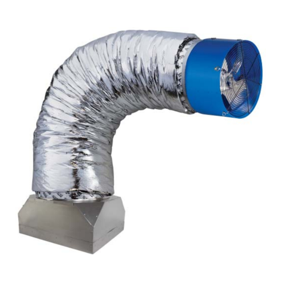
- Page 8 INSTALLATION: FAN & DUCT The next step in this fan’s installation is to hang the fan assembly from the attic’s rafters, and to attach it to the backdraft damper using the provided ductwork. Figure 8 below shows the fan assembly, ductwork, and backdraft damper as they should appear when fully installed.
- Page 9 Gently bend the ductwork to a 90° angle and slide the free end onto the fan cone and fasten it thereto using the self-tapping metal screws on the ductwork’s collar to the fan cone (as shown at right in Figure 10) Adhere to the following guidelines when attaching the ductwork to the backdraft damper and fan cone: •...
-
Page 10: Wall Switch Installation
INSTALLATION: WIRING & CONTROLS The fi nal step in this fan’s installation is to install its controls. The VentCool 1.8 unit can be equipped with two different control packages: 1st generation or 2nd generation. Either control package works the same with controlling the operation of the fan. -
Page 11: Start-Up And Operation
After unit and wall switch are installed, plug the attached power cord into a 120 Volt, 60 Hz, 9 amp minimum, grounded outlet with uninterrupted power. For reference, Figure 16 shows the general wiring scheme of the VentCool 1.8 system including optional accessories. Verify the resettable breaker on the electrical control box on fan assembly has not tripped. - Page 12 • If the damper fl aps do not open or close, visually inspect the damper for any debris obstructing their move- ment. • If the steps above do not work, contact Field Controls Tech Support at 800.742.8368 or by email at fi eldtec@fi eldcontrols.com for further assistance.
-
Page 13: Important Operating Tips
RMT port. Field Controls remote control transmitters and receivers are pre-merged at our factory. They may, however, be- come unmerged prior to installation. A remote control transmitter that has become unmerged from its reciever will not be able to control the fan. -
Page 14: Maintenance And Troubleshooting
• If the damper fl aps do not open or close, visually inspect the damper for any debris obstructing their movement. If the suggestions above do not work, contact Field Controls technical support at 800.742.8368 or by email at fi eldtec@fi eldcontrols.com for further assistance. - Page 15 page 15 of 16 P/N 78010007000 05/17 Rev B...
- Page 16 This manual may be downloaded and printed from the Field Controls website (www.fi eldcontrols.com) This manual may be downloaded and printed from the Field Controls website (www.fi eldcontrols.com) WARRANTY WARRANTY For warranty information about this or any Field Controls product, visit: For warranty information about this or any Field Controls product, visit: www.fi...
Need help?
Do you have a question about the VentCool 1.8 and is the answer not in the manual?
Questions and answers