Table of Contents
Advertisement
Quick Links
Advertisement
Table of Contents

Related Manuals for OWL ZOOM 2 ZO2


Summary of Contents for OWL ZOOM 2 ZO2
- Page 1 Optical Wavelength Laboratories OPERATIONS GUIDE ZOOM 2 OPTICAL POWER METER Model Numbers: ZO2V Revision 1.12 Optical Wavelength Laboratories (OWL) N9623 West US Hwy 12 Whitewater, WI 53190 Phone: 262-473-0643 Internet: OWL-INC.COM OWL-INC.COM...
-
Page 2: Table Of Contents
Active Equipment Power Measurement Fiber Continuity Patch Cable Testing Check MM Reference Cables with a Dual OWL MM Light Source Check MM Reference Cables with a WaveSource MM Light Source Check SM Reference Cables with a Laser OWL SM Laser Source... -
Page 3: Introduction
INTRODUCTION BEFORE YOU BEGIN All personnel testing optical fibers should be adequately trained in the field of fiber optics before using any fiber optic test equipment. If the user is not completely familiar with testing fiber optics, they should seek competent training. Such training can be acquired from a variety of sources, such as local hands-on training classes. -
Page 4: Applications
INTRODUCTION APPLICATIONS Below is a list of test and measurement applications that can be performed using the ZOOM 2 optical power meter. The procedure for each one of these applications is covered in detail in this manual. Active Equipment Optical Power Measurements. Active equipment should be measured periodically for correct power levels. The transmitters in this equipment have a known power value. -
Page 5: Precautions
INTRODUCTION PRECAUTIONS Safety - Exercise caution when working with any optical equipment. High-intensity fiber optic laser sources output potentially NEVER dangerous high energy invisible light, and could cause serious, irreparable damage to the eye. Thus, it is recommended to look into the connector port of a light source or the end of a fiber. Operational - It is important to keep connector ferrules and optical connector ports clean. -
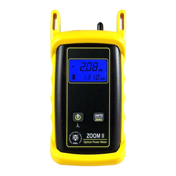
Page 6: General Features
INTRODUCTION GENERAL FEATURES DETECTOR 9VDC Charger Port / Optional VFL Port - Allows for charging of re- chargable 9-volt batteries, as well as wall power operation (9VDC transformer and 9-volt re-chargeable battery not included). DO NOT USE BATTERY CHARGING PORT WITH NON- RECHARGEABLE BATTERIES. -
Page 7: Test Procedures
TEST PROCEDURES ACTIVE EQUIPMENT POWER MEASUREMENT Required Accessories (1 or 2) one-meter patch cable(s) – (ensure proper connector type and fiber type) Direct Transmitter Output Power Measurement To measure the output power from a transmitter, use the following steps: Connect the ZOOM 2 to the transmitter port on the active equipment under test, as shown at right. -
Page 8: Fiber Continuity
TEST PROCEDURES FIBER CONTINUITY Required Accessories (2) one-meter patch cables – (ensure proper connector type and fiber type) Checking for Fiber Continuity 1 2 3 4 5 6 7 8 9 10 11 12 1 2 3 4 5 6 7 8 9 10 11 12 The ZOOM 2 can be used to verify continuity of a fiber link, or can be used to LIGHT SOURCE trace an optical fiber if the fibers are not properly labeled. -
Page 9: Patch Cable Testing
TEST PROCEDURES PATCH CABLE TESTING Required Accessories (3) one-meter patch cables – (ensure proper connector type and fiber type) (2) fiber optic adapters/couplers – (ensure proper connector type) Patch Cable Insertion Loss LIGHT SOURCE Patch cables should be tested periodically to ensure that they are okay to CONNECTOR PORTS use for testing. - Page 10 STEP 1 - Connect ZOOM 2 and Dual OWL STEP 5 - Power ON the Dual OWL Connect the ZOOM 2 and Dual OWL together with an orange multimode patch cable as shown below. Press to power on the Dual OWL.
- Page 11 Several cleaning cycles may be required. You may need to press the button several times. If the power level is still too low, even after a thorough cleaning and inspection and patch cable replacement, contact OWL technical support at 262-473-0643 for more information.
- Page 12 STEP 1 - Connect ZOOM 2 and Laser OWL STEP 5 - Power ON the Laser OWL Connect the ZOOM 2 and Laser OWL together with a yellow singlemode patch cable as shown below. Press to power on the Laser OWL.
- Page 13 STEP 1 - Connect ZOOM 2 and Laser OWL STEP 5 - Power ON the Laser OWL Connect the ZOOM 2 and Laser OWL together with a yellow singlemode patch cable as shown below. Press to power on the Laser OWL.
-
Page 14: Quick Reference Guides
QUICK REFERENCE GUIDES Optical Power Meter: ZOOM 2 Fiber Optic Light Source: DUAL OWL Series Multimode Sources PAGE 1 OF 5 Required Accessories (2-3) one-meter patch cables – ensure proper connector type and fiber type (1-2) fiber optic mandrel – used for setting references with multimode cables only; see table below for mandrel sizes multimode reference cables must be wrapped and secured around a mandrel as required by national and international Fiber Optic Test Procedures (FOTPs). - Page 15 Verify Patch Cable Press to power on the Dual OWL multimode light source. The 850nm port powers on first by default. Press to power on the ZOOM 2 optical power meter. Press several times on the ZOOM 2 until the wavelength is set to 850nm.
- Page 16 QUICK REFERENCE GUIDES Optical Power Meter: ZOOM 2 Fiber Optic Light Source: DUAL OWL Series Multimode Sources PAGE 3 OF 5 Verify Proper Operation of the Equipment, cont. Once proper operation has been verified, remove the second patch cable from both units and set it aside.
- Page 17 Remove the patch cable from the detector port on the ZOOM 2, and bring both units to the opposite ends of the link under test. Connect the ZOOM 2 and Dual OWL to the link under test as shown in Figure 5 below. 1 2 3 4 5 6 7 8 9 10 11 12...
- Page 18 QUICK REFERENCE GUIDES Optical Power Meter: ZOOM 2 Fiber Optic Light Source: DUAL OWL Series Multimode Sources PAGE 5 OF 5 Take Readings, cont. Press several times until the ZOOM 2 is set to 1300nm. Record the reading for the current fiber under test.
- Page 19 QUICK REFERENCE GUIDES Optical Power Meter: ZOOM 2 Fiber Optic Light Source: WaveSource Series Multimode Source PAGE 1 of 4 Required Accessories (2) one-meter patch cables – ensure proper connector type and fiber type (1) fiber optic mandrel – used for setting references with multimode cables only; see table below for mandrel sizes 50/125 µm 62.5/125 µm Diameter 0.9 in.
- Page 20 QUICK REFERENCE GUIDES Optical Power Meter: ZOOM 2 Fiber Optic Light Source: WaveSource Series Multimode Source PAGE 2 of 4 Verify Proper Operation of the Equipment Connect the power meter and light source together with the straight patch cable (i.e. no mandrel wrap) as shown in Figure 3. LIGHT SOURCE CONNECTOR PORTS SC connectors shown here;...
- Page 21 QUICK REFERENCE GUIDES Optical Power Meter: ZOOM 2 Fiber Optic Light Source: WaveSource Series Multimode Source PAGE 3 of 4 Verify Proper Operation of the Equipment, cont. Connect the power meter and light source together with the mandrel-wrapped patch cable as shown in Figure 4 below. LIGHT SOURCE CONNECTOR PORT NOTES: –...
- Page 22 QUICK REFERENCE GUIDES Optical Power Meter: ZOOM 2 Fiber Optic Light Source: WaveSource Series Multimode Source PAGE 4 of 4 TAKE READINGS Remove the patch cable from the detector port on the ZOOM 2, and bring both units to the opposite ends of the link under test, leaving the mandrel-wrapped cable attached to the WaveSource.
- Page 23 Connect the power meter and light source together with the first patch cable as shown in Figure 2. Press to power on the Laser OWL singlemode laser source. The 1310nm port powers on first by default. Press to power on the ZOOM 2 optical power meter.
- Page 24 QUICK REFERENCE GUIDES Optical Power Meter: ZOOM 2 Fiber Optic Light Source: LASER OWL Series Singlemode Sources PAGE 2 OF 3 Verify Proper Operation of the Equipment, cont. Press several times on the ZOOM 2 until the wavelength is set to 1310nm.
- Page 25 Remove the patch cable from the detector port on the ZOOM 2, and bring both units to the opposite ends of the link under test. Connect the ZOOM 2 and Laser OWL to the link under test as shown in Figure 3 below. 1 2 3 4 5 6 7 8 9 10 11 12...
- Page 26 QUICK REFERENCE GUIDES Optical Power Meter: ZOOM 2 Fiber Optic Light Source: WaveSource Series Singlemode Source PAGE 1 of 3 REQUIRED ACCESSORIES (2) singlemode patch cables EQUIPMENT PORTS Figure 1 shows the ports used during this procedure. These ports may vary depending upon the model of equipment. FIGURE 1 Test Equipment Ports Detector...
- Page 27 QUICK REFERENCE GUIDES Optical Power Meter: ZOOM 2 Fiber Optic Light Source: WaveSource Series Singlemode Source PAGE 2 of 3 FIGURE 2 Verify Patch LIGHT SOURCE CONNECTOR PORT NOTES: Cable – CONNECTOR TYPE MAY VARY – DO NOT INSERT ANGLED PHYSICAL CONTACT (APC) CONNECTOR SC connectors shown here;...
- Page 28 QUICK REFERENCE GUIDES Optical Power Meter: ZOOM 2 Fiber Optic Light Source: WaveSource Series Singlemode Source PAGE 3 of 3 1 2 3 4 5 6 7 8 9 10 11 12 1 2 3 4 5 6 7 8 9 10 11 12 FIGURE 3 Taking Readings...
-
Page 29: Operation/Maintenance
OPERATION/MAINTENANCE OPTIONAL VFL (visual fault locator) PORT As an option, a Visual Fault Locator (VFL) can be installed into the ZOOM 2 optical power meter in place of the charger port. The VFL is an invaluable troubleshooting tool with two important uses: Visual Fault Location. -
Page 30: Visual Fault Location
OPERATION/MAINTENANCE VISUAL FAULT LOCATION The optional VFL port in the ZOOM 2 VFL can be used as a troubleshooting tool to determine if there are breaks, micro-bends, or any other anomalies causing excessive loss within the first few feet of the fiber under test located in the splice tray. The bright red laser injects high-intensity red laser light into the near-end connector. -
Page 31: Visual Fiber Identification
OPERATION/MAINTENANCE VISUAL FIBER IDENTIFICATION The optional VFL port in the ZOOM 2 optical power meter can help take the guesswork out of identifying ports in a fiber patch panel or checking polarity of a duplex connector. Connect the VFL port to one end of a fiber link, and the high-intensity, precision-coupled red laser diode will allow the user to visually identify the port by the presence of a red glow emitting from the connector on the other end, allowing for visual port identification of fiber optic links up to 5 kilometers (3.1 miles) away. -
Page 32: Boot Removal
OPERATION/MAINTENANCE BOOT REMOVAL/REPLACING THE BATTERY Boot Removal To remove the boot from the ZOOM 2 optical power meter, place your thumb on the back of the unit, then use your fingers to pull the lip off of the front of the unit (as shown below). Battery Replacement The battery compartment is covered by a sliding plate on the back of the unit. -
Page 33: Universal Port
Use of SC Connectors with 2.5mm Universal Port Take extra care when inserting SC connectors into the 2.5mm universal port as the spring-loading action of the SC connector may cause improper insertion. Call OWL at (262) 473-0643 with any questions. -
Page 34: Cleaning The Detector Port
OPERATION/MAINTENANCE CLEANING THE DETECTOR PORT Required accessories: A) Isopropyl Alcohol (91% or better) B) Round wooden toothpick with sharp point (NOTE: do not use a metal pin or needle since metal will scratch the surface of the detector) C) Cotton swab D) Jeweler’s loupe (10x magnification recommended) E) Compressed Air (not shown) Place a small amount of cotton from the swab onto the wooden... -
Page 35: Cleaning The Optional Vfl Port
OPERATION/MAINTENANCE CLEANING THE OPTIONAL VFL PORT This cleaning procedure applies to the optional VFL port on the ZOOM 2 optical power meter. For more information about cleaning the DETECTOR port on the ZOOM 2, see page 23. Required Accessories: Isopropyl alcohol (91% or better) In-adapter fiber optic cleaning accessories, such as 2.5mm cleaning swabs or 2.5mm HUXCleaner™... -
Page 36: Auto Mode
NOTE: AUTO mode is only usable with OWL WaveSource light sources: Model numbers: WS-MDxx, WS-MDVxx, WS-SDxx, WS-VSDxx, and WS-MDSDxx SETTING UP AUTO MODE IN THE ZOOM 2 TO PERFORM DUAL-WAVELENGTH MEASUREMENTS Connect the ZOOM 2 optical power meter to the appropriate WaveSource light source port –... -
Page 37: Appendices
Calibration. It is recommended to have Optical Wavelength Laboratories calibrate this unit once per year. Warranty. The ZOOM 2 comes standard with a two-year factory warranty, which covers manufacturer defect and workmanship only. CONTACT INFORMATION Address: Phone: Internet: Optical Wavelength Laboratories, Inc. 262-473-0643 OWL-INC.COM N9623 US Hwy 12 Whitewater, WI 53190... -
Page 38: Optional Upgrade Information
APPENDICES OPTIONAL UPGRADE INFORMATION Visual Fault Locator Port Upgrade The ZOOM 2 optical power meter may be upgraded to include an optional visual fault locator (VFL), useful for locating bends, breaks, and other anomalies in the near-end splice tray, as well as visual fiber identification up to 5km away! Upgrading to a VFL port requires the charger port to be removed from the unit. -
Page 39: Link Budget Calculation Worksheet
LINK BUDGET CALCULATION WORKSHEET Operating Wavelength Fiber Type Calculate System Attenuation Fiber Loss at Operating Wavelength (Distance x Fiber Loss) Total Cable Distance Individual Fiber Loss (at operating wavelength) dB/km Total Fiber Loss Connector Loss (Connector Loss x Connector Pairs) Individual Connector Loss Number of Connector Pairs Total Connector Loss...
Need help?
Do you have a question about the ZOOM 2 ZO2 and is the answer not in the manual?
Questions and answers