Table of Contents
Advertisement
Quick Links
Advertisement
Table of Contents

Subscribe to Our Youtube Channel
Related Manuals for Fuji Electric ZKMA


Summary of Contents for Fuji Electric ZKMA
-
Page 2: Preface
Please do not use it for consumer use. This instruction manual should be delivered to the end user without fail. Manufacturer: Fuji Electric Co., Ltd. Type: Described in the nameplate put on the main body Date of manufacture: Described in the nameplate put on the main body... -
Page 3: Safety Precautions
SAFETY PRECAUTIONS First of all, read this “SAFETY PRECAUTIONS” carefully, and then use in the correct way. Installation, transportation, wiring, use, maintenance of this product shall be carried out by suitably trained personnel. First-time users should operate the instrument under the supervision of a fully competent person in the operation. - Page 4 Cautions on use If unusual smell or sound has been produced, immediately stop the DANGER instrument. Any discharge produced may cause a fire. Leaving the converter unused for a long time or restarting it after dis- CAUTION use requires procedures different from normal operation or suspension procedures.
-
Page 5: Warranty And Maintenance
4-2. Scope of warranty 1) If any failure or malfunction attributable to Fuji Electric occurs in the period of warranty, we shall pro- vide the product after repairing or replacing the faulty part for free of charge at the place of purchase or delivery. - Page 6 2) Regardless of the time period of the occurrence, Fuji Electric is not liable for the damage caused by the factors Fuji Electric is not responsible for, opportunity loss of the purchaser caused by malfunction of Fu- ji Electric product, passive damages, damage caused due to special situations regardless of whether it was foreseeable or not, and secondary damage, accident compensation, damage to products that were not manufactured by Fuji Electric, and compensation towards other operations.
- Page 7 10 years. Do not use capacitors beyond its lifetime. Otherwise, electrolyte leakage or depletion may cause odor, smoke, or fire. Please contact Fuji Electric or its service providers when an overhaul is required. 9. Spare parts and accessories Refer to “Checking of contents of the package”...
-
Page 8: Table Of Contents
3. INSTALLATION ............................5 3.1 Installation site ............................5 3.2 How to install the converter ........................6 3.2.1 Mounting on panel ( ZKMA ) ......................6 3.2.2 Pipe mounting (ZKMA) ........................6 3.2.3 Mounting on panel ( ZKMB ) ......................7 3.2.4 Pipe mounting ( ZKMB ) ........................ - Page 9 7. CALIBRATION ............................33 7.1 Preparation ............................. 33 7.2 Manual calibration ..........................34 7.3 Auto calibration (option) ........................36 7.4 Remote calibration ..........................38 7.5 All calibration (option) ........................... 40 8. BLOWDOWN (OPTION)......................... 41 8.1 Preparation for blowdown ........................41 8.2 Manual blowdown..........................
- Page 10 10.5.5 Lower limit setting of oxygen concentration ................. 83 10.5.6 HH limit setting of oxygen concentration ..................84 10.5.7 LL limit setting of oxygen concentration ..................85 10.5.8 Hysteresis Setting ........................... 86 10.5.9 Hold treatment setting (maintenance hold) ................... 88 10.5.10 Hold value setting (maintenance hold) ..................
-
Page 11: Checking Of Contents Of The Package
CHECKING OF CONTENTS OF THE PACKAGE Check that all of the following are contained in the delivered package. (1) Zirconia Oxygen Analyzer Converter main unit 1 unit (2) Accessories 1 set (Refer to the table below.) Table 1 Standard accessories Item Q'ty Remarks... -
Page 12: General
1. GENERAL This manual describes the installation, operation, and the maintenance of the zirconia oxygen analyzer con- verter. Read it carefully before using the converter. For the detector, flow guide tube and ejector used with the converter, refer to relevant instruction manuals. 1.1 Direct insertion type zirconia oxygen analyzer The direct insertion type zirconia oxygen analyzer consists of a direct insertion type zirconia detector (type ZFK) and converter (type ZKM). -
Page 13: Operating Parts And Their Functions
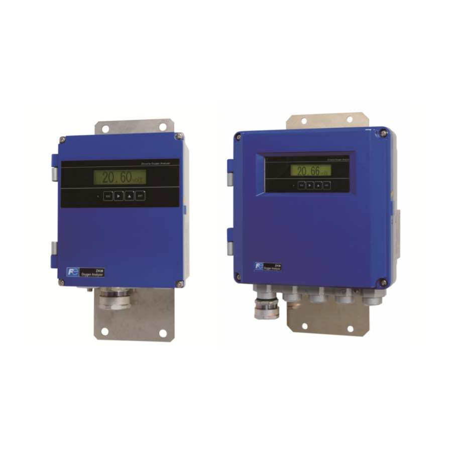
2. OPERATING PARTS AND THEIR FUNCTIONS 2.1 Outline Drawing (1) ZKMA (2) ZKMB - 2 - INZ-TN2ZKMA-E... -
Page 14: Terminal Block
2.2 Terminal block 2.3 Didplay and operation panel ① Display ② ⑥ ENT key ③ ESC key ④ Digit key Up key ⑤ Name Description Display unit Displays the concentration value and setting values. ① Lights during power supply. ② ESC key Used to return to the previous screen or exit the setting. -
Page 15: Internal Constitution
2.4 Internal constitution (1) ZKMA ② I/O board ① CPU board ③ Communication board (optional) ④ Fuse ⑦ Packing ⑤ Terminal block ⑥ Earth terminal (2) ZKMB You can see the CPU board, the I/O board, and the communication board (optional) if you remove the M3 screw and open the inner cover. -
Page 16: Installation
Secure at least 100 mm of space between the converter and nearby wall. Also secure a space of opening the front cover for maintenance. Secure a cable wiring space under the case. more 400 or more Unit: mm Top view of mounting (ZKMA) more 580 or more Unit: mm Top view of mounting (ZKMB) - 5 -... -
Page 17: How To Install The Converter
3.2 How to install the converter 3.2.1 Mounting on panel (ZKMA) Unit: mm Mounting dimensions Installation Name Quantity 4-M8 Converter Sems screw (M8×12) Code Standard tightening torque 12.5 [N ・ m] 3.2.2 Pipe mounting (ZKMA) Installation Name Quantity Converter Hexagon nut (M8) -
Page 18: Mounting On Panel (Zkmb)
3.2.3 Mounting on panel (ZKMB) Unit: mm Mounting dimensions Installation 4-M8 Name Quantity Converter Sems screw (M8×12) Code Standard tightening torque 12.5 [N ・ m] 3.2.4 Pipe mounting (ZKMB) Installation Name Quantity Converter Hexagon nut (M8) Spring washer (M8) Plain washer (M8) U bolt (M8) Support panel Code... -
Page 19: Wiring And Piping
4. WIRING AND PIPING DANGER Do not energize the transmitter or equipment connected to the transmitter until all the wiring work are completed. CAUTION This product is compliant with CE marking. If you need the product to meet the requirements of CE marking, carry out the wiring work ac- cording to the following instructions: ... -
Page 20: Before Wiring
4.1 Before wiring (1) Power voltage for the converter must conform to that for the detector to be connected. (2) Power supply wiring Use 1.25sq 600V vinyl insulated cable (JISC3307) or equivalent as power supply cable. Use the main ground wire longer than the L1 and L2 lines. ... -
Page 21: Wiring To Terminals
4.2 Wiring to terminals 4.2.1 Wiring to power supply and detector (1) <ZKMA> (2) <ZKMB> Note 1: Fix the exclusive cable (O sensor input / O sensor thermocouple input) with the cable gland so that its sheath is 10 mm or less. -
Page 22: Cable Gland And Input And Output Lines
4.2.2 Cable gland and input and output lines (1) <ZKMA> (2) <ZKMB> - 11 - INZ-TN2ZKMA-E... -
Page 23: Allocation Of The Terminal Block
4.2.3 Allocation of the terminal block - 12 - INZ-TN2ZKMA-E... -
Page 24: Wiring And Piping Diagram
4.3 Wiring and piping diagram 4.3.1.1 Flow guide tube system - 13 - INZ-TN2ZKMA-E... - Page 25 4.3.1.2 Flow guide tube system (with valve) - 14 - INZ-TN2ZKMA-E...
- Page 26 4.3.1.3 Ejector system - 15 - INZ-TN2ZKMA-E...
- Page 27 4.3.1.4 Ejector system (with valve) - 16 - INZ-TN2ZKMA-E...
-
Page 28: Handling Of Standard Gas (An Article On Separate Order)
4.4 Handling of standard gas (An article on separate order) 4.4.1.1 Operation (1) Make sure the handle is closed on the high pressure gas container, then detach the cap nut. (2) Attach the high pressure gas container using the cap nut with packing of the pressure reduction valve. (3) Make sure the secondary pressure adjusting valve is turned fully counterclockwise (pressure not ap- plied) and the outlet needle is turned fully clockwise (closed), then open the handle. -
Page 29: Operation
5. OPERATION 5.1 Preparation for operation Preparation can be performed after installation or on the bench. (1) Wiring check (Refer to “4.2”, “4.3”) (2) Confirmation of the power supply specifications (Please check the main power supply and the power supply voltage specification of the detector.) (3) Power ON. - Page 30 (8) Auto calibration (option) Automatic calibration may be performed at specified time intervals. Refer to “7.3” for automatic calibration settings. (9) Blowdown (option) A flow guide tube blowdown feature prevents the flow guide tube from clogging due to dust in the gas stream.
-
Page 31: Key Operation Flow Diagram (Outline)
5.2 Key operation flow diagram (outline) - 20 - INZ-TN2ZKMA-E... - Page 32 - 21 - INZ-TN2ZKMA-E...
- Page 33 - 22 - INZ-TN2ZKMA-E...
- Page 34 - 23 - INZ-TN2ZKMA-E...
-
Page 35: Initial Parameter Value Table
5.3 Initial parameter value table 5.3.1 Parameters related to measurement Reference Parameter setting Displayed message Range Initial value paragraph DISPLAY RANGE Display range Range1 or Range2 Range-1 10.1.1 RANGE1 RANGE2 Decimal point position DECIMAL POINT [00.00] Range1 [00.00] 10.1.2 [0.000] 00.00... -
Page 36: Parameters Related To Blowdown (Displayed If The Option Is Provided)
5.3.3 Parameters related to blowdown (displayed if the option is provided) Reference Parameter setting Displayed message Range Initial value paragraph BLOW DOWN Automatic blowdown (The automatic YES or NO 10.3.1 function blowdown func- tion is invalid.) START DATE Date and time for starting Date and time in the fu- 99/01/01 00:00 10.3.2... -
Page 37: Other Parameters
5.3.5 Other parameters Reference Parameter setting Displayed message Range Initial value paragraph DATE SET Date and time in the cal- Current date and time (14/01/01/ 00:00) 10.5.1 endar 00/00/01 00:00 DI1 to DI3 [NONE] [BLOW DOWN ON] [NONE] [HEATER OFF] DI 1 Contact inputs 1 to 3 [PROHIBIT CAL.]... - Page 38 Reference Parameter setting Displayed message Range Initial value paragraph MEAS. WAIT TIME Measurement recovery 0 to 300 sec. in 1 sec. 10 sec. 10.5.12 time steps 010 s KEY LOCK Key lock function YES or NO (Key lock func- 10.5.16 tion is invalid.) BACKLIGHT TIME 0 to 99...
-
Page 39: Operation Start And Stop
6. OPERATION START AND STOP 6.1 Operation start After correct wiring and piping has been completed, turn on the converter to start measurement. Note: 10 min. of warm-up time is necessary after power ON. Caution of before starting operation (1) Furnace operation should be started after an elapsed time of 10 minutes from the point of turn- ing ”ON”... -
Page 40: Actions During Operation
6.3 Actions during operation While the instrument is operating, the following displays can be changed. - 29 - INZ-TN2ZKMA-E... -
Page 41: Check The Contents Of Display
6.4 Check the contents of display The condition of the unit is displayed on the left of the LCD with three letters. The maximum of three items are displayed on one display. If there are four or more items, “▼” is displayed at the bottom of the screen. Scroll the screen with the key to display the fourth and subsequent items. -
Page 42: Checking The Error Information
6.4.2 Checking the error information Display State Remarks message Appears when control temperature of the heater exceeds Fault of heater temperature the set range. The heater control is stopped. Appears when disconnection is detected at the sensor, or Disconnection detection thermocouples for temperature control. -
Page 43: Oxygen Detector Standard Output Voltage
6.5 Oxygen detector standard output voltage concentration Output value concentration Output value concentration Output value (mV) (mV) (mV) 0.01 176.38 32.73 25.0 -4.475 123.15 10.0 16.71 30.0 -8.689 85.95 15.0 7.333 40.0 -15.34 69.93 20.0 0.683 50.0 -20.50 60.56 20.6 –... -
Page 44: Calibration
7. CALIBRATION In order to maintain good accuracy, proper calibration using standard gas is necessary. The following 4 methods of calibration are provided. (1) Manual calibration (“7.2”), (2) Auto calibration (option) (“7.3”), (3) Remote calibration (“7.4”), (4) All calibration (option) (“7.5”) 7.1 Preparation ... -
Page 45: Manual Calibration
7.2 Manual calibration Description Span/zero is calibrated once by key operation. Calibration must be made in the order of span and zero. Perform calibration after a calibration gas is supplied to the detector and the output signal of the de- tector becomes stable. - Page 46 Press the key to perform manual zero calibration. MANUAL ZERO CAL. If supplying calibration gas manually (without the auto- START calibration function) The operator shall open the span gas valve manually and adjust the flow rate to 1.5 ± 0.5 L/min. In the case of unit with the auto calibration function, an exter- nal solenoid valve can be driven by using the contact output signal from the terminal block.
-
Page 47: Auto Calibration (Option)
7.3 Auto calibration (option) Description Calibration is performed at time intervals set in advance. The solenoid valve is driven by contact signal to feed the standard gas for automatic calibration with span gas and zero gas. “CAL” is displayed on the left of the measurement screen during automatic calibration. ... - Page 48 The screen on the right appears. SET AUTO CAL AUTO CALIBRATION Press the key to display the screen on the right and press SET AUTO CAL key. START DATE The date and time for starting automatic calibration screen ap- pears. Use the key to set the auto calibration starting START DATE...
-
Page 49: Remote Calibration
7.4 Remote calibration This function is available only for the version with auto-calibration. You can perform all calibration by the contact input of the external terminal block. To perform remote calibration, install piping and wiring for the standard gas cylinder and the solenoid valve according to Section 4. - Page 50 Press the key. DI 1 REMOTE CAL. The screen on the right appears. DIGITAL INPUT Press the key several times and return to the measure- DI 1 ment screen. Close the contact set to the “REMOTE CAL.” 12.34 Remote calibration is performed. Vol% How to cancel ...
-
Page 51: All Calibration (Option)
7.5 All calibration (option) Description Perform sensor maintenance [sensor check (setting), span and zero calibration once for each sequen- tially by key operation. Actuate the solenoid valve attached to the exterior by the contact signal from the terminal block and supply standard gases sequentially. -
Page 52: Blowdown (Option)
8. BLOWDOWN (OPTION) In order to prevent the flow guide tube from clogging with dust contained in gas being measured, dust depos- its in the flow guide tube is removed by blowing compressed air such as instrumentation air, etc. Use the blowdown function by one of the following three methods. -
Page 53: Automatic Blowdown
8.3 Automatic blowdown Description Blowdown operation is performed at time intervals set in advance. Using contact signal from the terminal block, drive the solenoid valve and remove dust by blowing instrumentation air, etc. into the flow guide tube with blowdown nozzle. ... - Page 54 Use the key to set the auto blowdown starting START DATE date and time. 15/02/25 13:00 (Set the date and time of the future.) Press the key to set the value. Press the key. START DATE 15/02/25 13:00 The screen on the right appears. SET AUTO BLOW START DATE (10)
-
Page 55: Remote Blowdown
8.4 Remote blowdown You can perform blowdown by the contact input of the external terminal block. To perform remote blowdown, install piping and wiring for the supply air and the solenoid valve according to Section 4. (1) Set one of the contact inputs DI 1 to 3 to “Blowdown ON” in accordance with the following opera- tion procedure. - Page 56 Press the key. DI 1 BLOW DOWN ON The screen on the right appears. DIGITAL INPUT Press the key several times and return to the measurement DI 1 screen. Close the contact set to the “Blowdown ON.” 12.34 Blowdown is performed. Vol% How to cancel ...
-
Page 57: Maintenance And Check
1 set For the cable gland used to connect *ZZPZKM2 - TQ502593P3 the detector. Packing Small packing for the cable gland (op- *ZZPZKM2 - TK7M6120P1 tional) for ZKMA Packing Large packing for the cable gland (op- *ZZPZKM2 - TK7M6120P2 tional) for ZKMA O-rings These are the parts used for the case *ZZPZKM2 -... -
Page 58: Replacement Of Fuse
9.3 Replacement of fuse If a fuse blows, turn off the power, and replace the fuse after investigating the cause. Open the front door and you can see the a fuse on the case. To replace the fuse, insert a flathead screwdriver or coin into the fuse cap and turn it to the left while pressing it in order to remove the cap and replace the fuse. -
Page 59: Adjustment Of Monitor Contrast
(VR1) on the CPU board. Turn the knob with a flathead screwdriver to adjust the contrast. ZKMA Open the front cover and the inner cover, and you can see the volume knob (VR1) on the CPU board. Turn the knob with a flat- head screwdriver to adjust the contrast. -
Page 60: Troubleshooting
9.5 Troubleshooting Phenomena Probable causes Checking methods (normal value) Remedy No display Converter fuse blown out Check the fuse and supply voltage speci- Replace fuse Check fication. Power supply voltage Indication does Filter and/or flow guide tube Visual check of filter and flow guide Clean or replace filter not change or clogged... - Page 61 Phenomena Probable causes Checking methods (normal value) Remedy Replace the defec- Disconnection Break of thermocouples Cable check of wiring detection error Break of sensor Wiring check tive parts. Wrong wiring Correct wiring Turn on/off the power supply. Range cannot “Range setting”...
-
Page 62: Setting And Operating Of Parameter
10. SETTING AND OPERATING OF PARAMETER 10.1 Measured menu 10.1.1 Display range setting screen Description You can set the display range of oxygen concentration value using this function. Settable range: Select one of the following (1) “Range 1”: Displayed in the range set in the range setting 1. (2) “Range 2”: Displayed in the range set in the range setting 2. -
Page 63: Decimal Point Position Setting Screen
10.1.2 Decimal point position setting screen Description You can set the decimal point position of full scale for oxygen concentration display using this func- tion. Settable range: Select one of the following. (1) “00.00”: Displayed with two-digit integer and two decimal places. (2) “0.000”: Displayed with one-digit integer and three decimal places. -
Page 64: Full Scale Setting Screen
10.1.3 Full scale setting screen Description You can set the full scale value for display of oxygen concentration value using this function. Settable range: If the decimal point position is set to “00.00”: 02.00 to 50.00 vol% If the decimal point position is set to “0.000”: 2.000 to 9.000 vol% Operation Setting the full scale value to 20.00% (Range-1) (example) -
Page 65: Setting Screen For Calculation Time Of Maximum And Minimum Values Appears
10.1.4 Setting screen for calculation time of maximum and min- imum values appears Description You can set the calculation time of maximum and minimum values of oxygen concentration value using this function. Settable range: 0 to 240h Operation Setting the calculation time of maximum and minimum values to 24 hours (example) Displayed message... -
Page 66: Calibration Menu
10.2 Calibration menu 10.2.1 Automatic calibration setting (option) Description You can set the automatic calibration to valid or invalid using this function. If changing the automatic calibration setting from valid to invalid during automatic calibration or re- mote calibration, the calibration is forcibly canceled. Operation Setting the automatic calibration to valid (example) -
Page 67: Date And Time For Starting Automatic Calibration (Option)
10.2.2 Date and time for starting automatic calibration (option) Description You can set the date and time for starting automatic calibration using this function. Automatic calibration is performed in a specified cycle from a specified date and time. If it is invalid, the automatic calibration does not start at a specified date and time. ... -
Page 68: Cycle Time Setting Of Automatic Calibration (Option)
10.2.3 Cycle time setting of automatic calibration (option) Description You can set the automatic calibration cycle using this function. The cycle starts from a specified date and time for automatic calibration. Settable range: 00d 00h to 99d 23h (h: 00 to 23) Operation Setting the automatic calibration so that it is performed every four days (example) -
Page 69: Performing All Calibration (Option)
10.2.4 Performing all calibration (option) Description You can perform all calibration on the screen using this function. Zero calibration is automatically performed after the span calibration. You cannot perform “All calibration” during warming-up operation. Operation Performing all calibration on the screen (example) Displayed message Key operation... -
Page 70: Performing A Manual Span Calibration
10.2.5 Performing a manual span calibration Description Before starting span calibration, the operator shall supply span gas to the detector and check that the display is stabilized. You cannot perform manual span calibration during warming-up operation. Operation Performing span calibration on the screen (example) Displayed message Key operation... -
Page 71: Performing A Manual Zero Calibration
10.2.6 Performing a manual zero calibration Description Before starting zero calibration, the operator shall supply zero gas to the detector and check that the display is stabilized. You cannot perform manual zero calibration during warming-up operation. Operation Performing zero calibration on the screen (example) Displayed message Key operation... -
Page 72: Calibration Gas Setting
10.2.7 Calibration gas setting Description Set calibration gas concentration (span/zero calibration gas concentrations). Use the calibration gas concentration 1 for the range 1, and the calibration gas concentration 2 for the range 2. Use normal air (atmosphere) as a span calibration gas and set its concentration to 20.600% O ... -
Page 73: Calibration Waiting Setting (Option)
10.2.8 Calibration waiting setting (option) Description Set the waiting time from supply of calibration gas to start of calibration. (Set the time so that the calibration gas becomes stable before the calibration.) Settable range: 10 to 999sec. Operation Setting the waiting time before the start of calibration to 20 seconds (example) Displayed message... -
Page 74: Calibration Error Clear
10.2.9 Calibration error clear Description You can clear the errors occurred during calibration using this function. If an error occurs during calibration, an error display (Er4, Er5) and abnormal contact output (close) continues until the next calibration is properly completed. ... -
Page 75: Operation Setting Screen Of Calibration Range
10.2.10 Operation setting screen of calibration range Description During calibration, you can select single or common range for the calibration factor using this func- tion. Settable range: Select one of the following. (1) “Range interlock”: Performs calibration of the range that is currently displayed and sets the calibration factors of the other ranges to the same value as above. -
Page 76: Blowdown Menu (Option)
10.3 Blowdown menu (option) 10.3.1 Automatic blowdown setting Description You can set the automatic blowdown to valid or invalid using this function. If changing the automatic blowdown setting from valid to invalid during automatic blowdown, the blowdown is forcibly canceled. Operation Setting the automatic blowdown to valid (example) -
Page 77: Date And Time Setting Of Automatic Blowdown
10.3.2 Date and time setting of automatic blowdown Description You can set the date and time for starting automatic blowdown using this function. Automatic blowdown is performed in a specified cycle from a specified date and time. If it is invalid, automatic blowdown does not start at a specified date and time. ... -
Page 78: Automatic Blowdown Cycle Setting
10.3.3 Automatic blowdown cycle setting Description You can set the automatic blowdown cycle using this function. The cycle starts from a specified date and time for automatic blowdown. Settable range: 00h 00m to 99h 59m (m: 00 to 59) Operation Setting automatic blowdown cycle to 24 hours. -
Page 79: Procedure For Setting Blowdown Time
10.3.4 Procedure for setting blowdown time Description You can set the blowdown time using this function (common with manual blow down). Settable range: 0 to 999 sec. Operation Setting blowdown time to 30 seconds. (example) Displayed message Key operation Description (LCD) Display the screen on the right in accordance with the key op-... -
Page 80: Perfoming Manual Blowdown
10.3.5 Perfoming manual blowdown Description You can perform blowdown on the screen using this function. If you perform remote control (calibration, blowdown, turning off the heater) during manual blow- down, remote control is prioritized and manual blowdown is stopped. Operation Performing blowdown on the screen (example) -
Page 81: Maintenance Menu
10.4 Maintenance menu 10.4.1 Error log display Description You can display an error log on the screen using this function. A latest piece of error information is displayed first. The maximum of 12 pieces of error information are saved. Press the key to display the older pieces of error information. - Page 82 Error logs Display message Status Sensorline Error Sensor line disconnection of the zirconia oxygen sensor was detected. TC-line Error Temperature control line disconnection of the zirconia oxygen sensor was detected. Sub temp. Error Line disconnection of the thermocouple for combustion control was detected. Warm-up was not completed within the warm-up monitoring time (45 minutes).
-
Page 83: Clearing Error Logs
10.4.2 Clearing error logs Description You can clear all error logs saved using this function. Operation Clearing all error logs saved (example) Displayed message Key operation Description (LCD) Display the screen on the right in accordance with the key op- MAINTE MENU eration summary and press the key. -
Page 84: Alarm Log Display
10.4.3 Alarm log display Description You can display alarm logs on the screen using this function. A latest piece of alarm information is displayed first. The maximum of 12 pieces of alarm information are saved. Press the key to display the older pieces of alarm information. The latest piece of alarm information is displayed next to the oldest piece of alarm information. -
Page 85: Clearing Alarm Logs
10.4.4 Clearing alarm logs Description You can clear all alarm logs using this function. Operation Clearing all alarm logs saved (example) Displayed message Key operation Description (LCD) Display the screen on the right in accordance with the key op- MAINTE MENU eration summary and press the key. -
Page 86: Performing A Manual Sensor Check
10.4.5 Performing a manual sensor check Description Manually supply atmospheric air or air from cylinder to the detector in order to measure the electro- motive force of the sensor. Operation Performing a sensor check on the screen (example) Key operation Description Displayed message Display the screen on the right in accordance with the key op-... -
Page 87: Maintenance Mode Setting
10.4.6 Maintenance mode setting Description You can set the maintenance mode to valid or invalid with this function. If the maintenance mode is set to valid, the analog output signal is held at the set value (see “10.5.10 Hold value setting.”) and the contact output for maintenance of the external contact is on. -
Page 88: Password Setting
10.4.7 Password setting Description You can set a password for switching the “Key lock function” valid /invalid, which is to prevent unau- thorized people from making various setting or operating the unit manually (modification, etc.) Note: Refer to “Setting of key lock” Paragraph (“10.5.16”). ... -
Page 89: Pid Auto Tuning
10.4.8 PID auto tuning Description Heater temperature of the detector is PID controlled. This "PID auto-tuning" function optimizes each value of P (proportion), I (integration) and D (derivation) for the environment where the unit is in- stalled. Note: Each value of P, I, and D has been set at factory. If temperature is not properly controlled, per- form PID auto tuning. -
Page 90: Parameter Menu
10.5 Parameter menu 10.5.1 Current date and time setting Description You can set a current date and time for the unit using this function. Settable range: date and time in the future in the calendar Operation Setting the current date and time to 13:00, 2015/02/25 (example) Displayed message Key operation... -
Page 91: Contact Input Setting
10.5.2 Contact input setting Description You can set the functions for the contact inputs 1 to 3 using this function. Settable range: Select one of the following (1) [NONE] : Performs no treatment by contact input. (2) [BLOW DOWN ON] : Performs blowdown by contact input. (Switch OFF to ON to perform blowdown.) (3) [HEATER OFF] : Turn off the heater by contact input. -
Page 92: Selection Of Alarm Contact Output
10.5.3 Selection of alarm contact output Description You can set the alarm conditions for alarm contact output using this function. Settable range: Select one of the following. (1) [ALARM NONE] : Alarm contact output is not performed. (2) [HIGH ALARM] : Alarm contact output is performed when an high limit alarm occurs. -
Page 93: High Limit Setting Of Oxygen Concentration
10.5.4 High limit setting of oxygen concentration Description You can set the high limit of oxygen concentration using this function. Use the oxygen concentration alarm 1 for the range 1, and the oxygen concentration alarm 2 for the range 2. ... -
Page 94: Lower Limit Setting Of Oxygen Concentration
10.5.5 Lower limit setting of oxygen concentration Description You can set the lower limit of oxygen concentration using this function. Use the oxygen concentration alarm 1 for the range 1, and the oxygen concentration alarm 2 for the range 2. ... -
Page 95: Hh Limit Setting Of Oxygen Concentration
10.5.6 HH limit setting of oxygen concentration Description You can set the HH limit of oxygen concentration using this function. Use the oxygen concentration alarm 1 for the range 1, and the oxygen concentration alarm 2 for the range 2. ... -
Page 96: Ll Limit Setting Of Oxygen Concentration
10.5.7 LL limit setting of oxygen concentration Description You can set the LL limit of oxygen concentration using this function. Use the oxygen concentration alarm 1 for the range 1, and the oxygen concentration alarm 2 for the range 2. ... -
Page 97: Hysteresis Setting
10.5.8 Hysteresis Setting Description You can set the hysteresis for alarm condition of oxygen concentration. Use the oxygen concentration alarm 1 for the range 1, and the oxygen concentration alarm 2 for the range 2. Perform the setting using the percentage (%) of the range compared to the full scale. ... - Page 98 Hysteresis : If the value fluctuates around the condition value, there is a possibility that alarms occur frequent- ly. When determining alarms, set a hysteresis width for the condition in order to prevent chattering. For alarm check, set the percentage (%) of the range compared to the full scale as hysteresis width (see the figure below).
-
Page 99: Hold Treatment Setting (Maintenance Hold)
10.5.9 Hold treatment setting (maintenance hold) Description You can set if the analog output hold function is valid or invalid using this function. If the analog output hold function is valid, the value set for the analog output (see “10.5.10 Hold value setting (maintenance hold)”) is held at the value set for analog output when the following treatment is performed. -
Page 100: Hold Value Setting (Maintenance Hold)
10.5.10 Hold value setting (maintenance hold) Description Using this function, you can set (select) the output value of analog output signal when the analog out- put hold function (maintenance hold) is enabled. If the maintenance mode is set to “Valid,” analog output signal is held at the value set in this proce- dure. -
Page 101: Setting Of Hold Setting Value (Maintenance Hold)
10.5.11 Setting of hold setting value (maintenance hold) Description Using this function, you can set the output value of analog output signal to an arbitrary value when the analog output hold function (maintenance hold) is enabled. This function is to set the output value of an analog output at a percentage (%) of the full-scale value, when “setting value”... -
Page 102: Setting Of Measurement Recovery Time (Maintenance Hold)
10.5.12 Setting of measurement recovery time (maintenance hold) Description This function is to set the recovery time (hold of extension) from the analog output hold function (maintenance hold). Settable range: 0 to 300 sec. Operation Setting the time for extension of hold to “10 seconds” (example) Displayed message Key operation... -
Page 103: Hold Treatment Setting (Error Hold)
10.5.13 Hold treatment setting (error hold) Description Using this function, you can set whether the analog output hold function is valid or invalid when an error occurs. If the analog output hold function (error hold) is set to valid, analog output signal is held at the set value (see “10.5.14 Hold value setting (error hold)”) if an error occurs. -
Page 104: Hold Value Setting (Error Hold)
10.5.14 Hold value setting (error hold) Description Using this function, you can set (select) the output value of analog output signal when the analog out- put hold function (error hold) is enabled. If the maintenance mode is set to “Valid,” analog output signal is held at the value set in this proce- dure. -
Page 105: Setting Of Hold Setting Value (Error Hold)
10.5.15 Setting of hold setting value (error hold) Description Using this function, you can set the output value of analog output signal to an arbitrary value when the analog output hold function (error hold) is enabled. This function is enabled if “Setting value” is set at “10.5.14 Hold value setting (error hold).” ... -
Page 106: Setting Of Key Lock
10.5.16 Setting of key lock Description Authorized person can set if the key lock is valid or invalid using this function. You need a “password” to make a setting if the key lock is valid or invalid. Note: Refer to “Password setting” (Paragraph “10.4.7”). ... -
Page 107: Setting Of Automatic Off Time
10.5.17 Setting of automatic OFF time Description You can set the time for automatically turning off the backlight of the LCD (screen) using this func- tion. When the time set for turning off the backlight elapses after the last operation, the backlight is turned off. -
Page 108: Station Number Setting
10.5.18 Station number setting Description You can set the station number of the unit for MODBUS communication using this function. Settable range: 0 to 99 Operation Setting the station number to 01 (example) Displayed message Key operation Description (LCD) Display the screen on the right in accordance with the key op- PARAMETER MENU... -
Page 109: Adjustment Screen For Analog Output 0
10.5.19 Adjustment screen for analog output 0% Description You can adjust the analog output 0% using this function. Operation Adjusting the analog output 0% (4 mA) (example) Displayed message Key operation Description (LCD) Connect the ammeter to the analog output terminals (5) – (6). Display the screen on the right in accordance with the key op- PARAMETER MENU eration summary and press the... -
Page 110: Adjustment Screen For Analog Output 100
10.5.20 Adjustment screen for analog output 100% Description You can adjust the analog output 100% using this function. Operation Adjusting the analog output 100% (20 mA) (example) Displayed message Key operation Description (LCD) Connect the ammeter to the analog output terminals (5) – (6). Display the screen on the right in accordance with the key op- PARAMETER MENU eration summary and press the... -
Page 111: Fuel Coefficient Setting (Option)
10.5.21 Fuel coefficient setting (option) Description You can set the fuel coefficient [k], which is for calculation of combustion efficiency, using this func- tion. Settable range : 0.00 to 1.99 Operation Setting the fuel coefficient [k] to 0.73. (example) Displayed message Key operation... -
Page 112: Factory Menu
10.6 Factory menu 10.6.1 Password setting screen Description You can input the password for authorization authentication in this screen in order to execute the fac- tory setting menu. Customers cannot execute the factory setting menu. This password is ditferent from the password you set in “10.4.7 Password setting ”. -
Page 113: Specifications
11. SPECIFICATIONS 11.1 Specifications - 102 - INZ-TN2ZKMA-E... - Page 114 - 103 - INZ-TN2ZKMA-E...
-
Page 115: Code Symbols
11.2 Code symbols <Converter> - 104 - INZ-TN2ZKMA-E... - Page 116 <Detector> - 105 - INZ-TN2ZKMA-E...
- Page 117 <Ejector> < Exclusive cable > - 106 - INZ-TN2ZKMA-E...
Need help?
Do you have a question about the ZKMA and is the answer not in the manual?
Questions and answers