Table of Contents
Advertisement
Turbine Package Operators Manual
Chapter 1
Turbine Package System Overview
Engine Core Assembly ...................................................................................................................5
General Description...................................................................................................................................5
Air Inlet Casing...........................................................................................................................................5
Compressor Inlet Bearing Housing Assembly........................................................................................5
Compressor Stator Casings......................................................................................................................5
Center Casing and Bearing Housing Assembly......................................................................................6
Combustion System ..................................................................................................................................6
Compressor Turbine Outer Casing ..........................................................................................................6
Compressor Turbine Nozzle Assembly Stage 1 and Duct .....................................................................6
Turbine Rotor Assemblies ........................................................................................................................6
Power Turbine Outer Casing and Interduct Assembly ...........................................................................7
Power Turbine Bearing Housing ..............................................................................................................7
Exhaust Diffuser ........................................................................................................................................7
Auxiliary Gearbox ......................................................................................................................................7
Cooling and Sealing Air System...............................................................................................................7
Turbine Instrumentation............................................................................................................................8
Temperature Monitoring ........................................................................................................................................... 8
Speed monitoring ..................................................................................................................................................... 8
Vibration Monitoring ................................................................................................................................................. 8
Pressure Monitoring ................................................................................................................................................. 8
Turbine Core Auxiliary Equipment ...........................................................................................................9
Variable Guide Vane (VGV) Actuator....................................................................................................................... 9
Interstage Bleed Valve ............................................................................................................................................. 9
P2 Blow-off Valves ................................................................................................................................................... 9
Waterwash Nozzles.................................................................................................................................................. 9
Auxiliary Gearbox ....................................................................................................................................10
Lubricating Oil System .................................................................................................................11
General Description.................................................................................................................................11
Lubricating Oil Tank ............................................................................................................................................... 11
Lubricating Oil Pumps ............................................................................................................................................ 11
Temperature Control Valve .................................................................................................................................... 12
Pressure Control Valve .......................................................................................................................................... 12
Lubricating Oil Filters.............................................................................................................................................. 12
Oil Cooler Circuit .................................................................................................................................................... 12
1-1
s
Advertisement
Table of Contents

Related Manuals for Siemens SGT-400


Summary of Contents for Siemens SGT-400
-
Page 1: Table Of Contents
Turbine Package Operators Manual Chapter 1 Turbine Package System Overview Engine Core Assembly ........................5 General Description...........................5 Air Inlet Casing............................5 Compressor Inlet Bearing Housing Assembly..................5 Compressor Stator Casings........................5 Center Casing and Bearing Housing Assembly..................6 Combustion System ..........................6 Compressor Turbine Outer Casing ......................6 Compressor Turbine Nozzle Assembly Stage 1 and Duct ..............6 Turbine Rotor Assemblies ........................6 Power Turbine Outer Casing and Interduct Assembly ................7... - Page 2 Chapter 1 Turbine Package System Overview Oil Mist Eliminator ..............................12 Lubricating Oil Tank Breather System Flame Trap (if applicable)................12 Secondary Breather Flame Traps (if applicable)....................12 Instrumentation............................12 Temperature Monitoring ............................13 Pressure Monitoring ............................... 13 Lubricating Oil Tank Level Monitoring ........................13 Lubricating Oil System Requirements ....................13 Fuel System ...........................15 General Description..........................15...
- Page 3 Turbine Package Operators Manual Chapter 1 Turbine Package System Overview Hydraulic Pump Boost Flow Oil Filter........................24 Starter Clutch ................................. 24 Turbine Underbase, Enclosure and Air Supply/Exhaust Systems..........25 Introduction ..............................25 Underbase ..............................25 Turbine Acoustic Enclosure ........................25 Ventilation System...........................25 Dampers................................. 26 Ventilation Inlet and Outlet Silencers ........................
- Page 4 Chapter 1 Turbine Package System Overview Electrical Operation ..........................34 Generator Control System ........................34 General Description..............................34 Operation................................34 Control Panels and Electrical Equipment Cabinets ..............35 Introduction ..............................35 Unit Control System ..........................35 General Description..............................36 Human / Machine Interface (HMI) .......................... 36 Generator Monitoring &...
-
Page 5: Engine Core Assembly
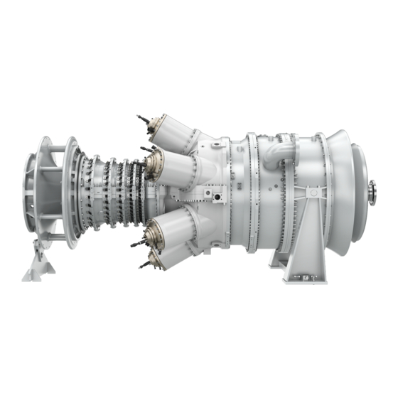
Turbine Package System Overview Engine Core Assembly The SGT-400 is a twin shaft, simple open cycle; non-regenerative industrial gas turbine designed for both power generation and mechanical drive applications. The core engine consists of a radial inlet casing through which air enters the eleven stage axial compressor for compression prior to entry to the combustion system. -
Page 6: Center Casing And Bearing Housing Assembly
Chapter 1 Turbine Package System Overview The HP compressor stator casing is in the form of an insert split along its horizontal centerline and located in the pressure casing back plate. The HP compressor stator blades being retained by dovetail grooves in the insert. Center Casing and Bearing Housing Assembly The Center Casing and Bearing Housing Assembly provide support for the hot end of the gas generator assembly, including the combustion system and the Compressor Turbine (CT) Outer... -
Page 7: Power Turbine Outer Casing And Interduct Assembly
Compressor air is used for sealing at labyrinth seals and cooling of high temperature components. Refer to the COOLING AND SEALING AIR SYSTEM DIAGRAM – SGT-400 (MW-2-1) located in this Manual Volume. Medium pressure air, taken from the bleed band at the seventh stage of the compressor, is used to: •... -
Page 8: Turbine Instrumentation
Chapter 1 Turbine Package System Overview Turbine Instrumentation Instrumentation is provided to monitor the turbine parameters and provide warning and trip control functions. Refer to the Turbine Instrumentation schematic diagram located in this Manual Volume. Temperature Monitoring Temperature detectors (RTD1 and RTD48) mounted in the air inlet casing, and thermocouples (TC1 to TC13 inclusive), mounted in the gas generator exhaust outlet, monitor compressor turbine operating temperature and temperature deviation. -
Page 9: Turbine Core Auxiliary Equipment
Turbine Package Operators Manual Chapter 1 Turbine Package System Overview Turbine Core Auxiliary Equipment Variable Guide Vane (VGV) Actuator The purpose of the variable guide vane (VGV) system is to vary the flow through the gas generator to optimize starting and running conditions. This is achieved by altering the angles at which the inlet guide vanes and the first three stages of compressor blades are presented to the airflow. -
Page 10: Auxiliary Gearbox
Chapter 1 Turbine Package System Overview Auxiliary Gearbox The auxiliary gearbox is mounted via an adaptor ring directly off the gas generator inlet bearing housing and driven from the gas generator shaft. It contains the necessary auxiliary drives for the hydraulic starter motor and its associated clutch, and the main lubricating oil pump. 1-10... -
Page 11: Lubricating Oil System
Turbine Package Operators Manual Chapter 1 Turbine Package System Overview Lubricating Oil System Mineral lubricating oil is used to lubricate and cool the turbine journal and thrust bearings, the generator bearings and the gearbox bearings, gears and splines. The oil is also used as a hydraulic oil to operate the hydraulic starting system when starting the turbine. -
Page 12: Temperature Control Valve
Chapter 1 Turbine Package System Overview Temperature Control Valve A temperature control valve (XV428) operates at a set value to divert lubricating oil through the oil cooler (TH1) as necessary to maintain the temperature of the oil at the optimum level. Pressure Control Valve Pressure control valve (PCV1) maintains a constant oil pressure to the bearings during turbine running. -
Page 13: Temperature Monitoring
Turbine Package Operators Manual Chapter 1 Turbine Package System Overview Temperature Monitoring A resistance temperature detector (TT7) mounted in the lubricating oil supply tank monitors the tank oil temperature and provides a permissive signal for tank immersion heater(s) control. The information is also used to inhibit a start until the tank oil temperature is above a set value. - Page 14 Chapter 1 Turbine Package System Overview This page intentionally left blank. 1-14...
-
Page 15: Fuel System
Turbine Package Operators Manual Chapter 1 Turbine Package System Overview Fuel System The fuel system is designed to deliver fuel to the combustion system at the correct pressure and flow required for the applicable power demand. General Description The schematic diagrams of the Fuel System can be found in this Manual Volume. The fuel system comprises: Off-skid Components •... -
Page 16: Demister Or Filter/Coalescer (If Applicable)
Chapter 1 Turbine Package System Overview Demister or Filter/Coalescer (if applicable) The off-skid demister or filter/coalescer is used to remove liquids and particulates from the gas fuel. The gas enters the filter/colaescer at the inlet pipe and passes through a special filter element into the top chamber, from where it leaves the filter/colaescer in a clean dry condition via the outlet pipe. -
Page 17: Electronic Control Unit (Ecu)
Turbine Package Operators Manual Chapter 1 Turbine Package System Overview Electronic Control Unit (ECU) The ECU is an integral part of the fuel system and interfaces with the fuel control valve actuator and the turbine governor to provide accurate fuel control, utilizing a high-speed microprocessor at its heart. -
Page 18: Temperature Monitoring
Six temperature sensors (TC255–TC260) mounted in each of the burner assemblies continuously monitor burner operation and provide operational data to the turbine control system. Fuel System Requirements Refer to the SIEMENS Fluids Specification 65/0027, which is located in this Manual Volume, for more specific information on fuel requirements. 1-18... -
Page 19: Air Distribution System
The air distribution system delivers the air through a system of pipework and manifolds to the various components. Refer to the SIEMENS Fluid Specification 65/0027, which is located in this Manual Volume, for specific information on the instrument air quality requirements. -
Page 20: P2 Blow-Off Valve Air Manifold
Chapter 1 Turbine Package System Overview P2 Blow-Off Valve Air Manifold Instrument air is supplied to the P2 blow-off valves via the air manifold during engine start and shutdown. The P2 blow-off valve system is protected from excessive pressure by a pressure relief valve (PSV159). -
Page 21: Ignition System
Turbine Package Operators Manual Chapter 1 Turbine Package System Overview Ignition System Introduction During the start up cycle, a high-energy pulse spark from the ignition system is used to ignite the combustion chamber air/fuel mixture. General Description The ignition system consists of a high-energy spark generator mounted in the underbase, with each combustor flame tube having its own igniter assembly (IG1 to IG6), which is permanently fixed. - Page 22 Chapter 1 Turbine Package System Overview This page intentionally left blank. 1-22...
-
Page 23: Starting System
Turbine Package Operators Manual Chapter 1 Turbine Package System Overview Starting System The turbine is started with a hydraulic transmission system driving through an overrunning clutch assembly on the auxiliary gearbox. The turbine rotor is accelerated to a speed at which fuel may be introduced into the combustion system and ignited to provide self-sustained acceleration, up to the normal operating speed. -
Page 24: Hydraulic Pump Boost Flow Oil Filter
Chapter 1 Turbine Package System Overview Hydraulic Pump Boost Flow Oil Filter A high-pressure filter (XF14) and bypass valve assembly (XV185) filters the oil to the hydraulic pump. The filter housing is fitted with a pop up indicator button to provide a visual indication of filter blockage. -
Page 25: Turbine Underbase, Enclosure And Air Supply/Exhaust Systems
Turbine Package Operators Manual Chapter 1 Turbine Package System Overview Turbine Underbase, Enclosure and Air Supply/Exhaust Systems Introduction The underbase forms a structure for mounting the turbine, auxiliary gearbox and associated systems. An acoustic enclosure is provided over the turbine, interfacing with the underbase, to reduce noise levels from the machinery to an acceptable level. -
Page 26: Dampers
Chapter 1 Turbine Package System Overview Dampers Control system activated dampers are located at the enclosure ventilation inlet and outlet openings, which close when a fire is detected to retain the fire extinguishant. The dampers are also closed when the unit is in standby mode. Ventilation Inlet and Outlet Silencers Silencers are provided to reduce noise emissions through the ventilation ducting from the gas turbine and the ventilation fan(s). -
Page 27: Combustion Air System
Turbine Package Operators Manual Chapter 1 Turbine Package System Overview Combustion Air System Air Inlet Filter - Marine Type (if applicable) The combustion air intake filter (XF34) is of the high velocity, high efficiency multi-stage type consisting of five stages. The first stage of the filter consists of a weather hood and bird screen. -
Page 28: Acoustic Lagging
Chapter 1 Turbine Package System Overview Acoustic Lagging To meet site noise emission requirements, the intake system may be acoustically lagged up to and including the air intake silencer. As a minimum, the lagging will have sufficient physical properties to meet the package noise level requirements. Instrumentation The air intake filter pressure drop is monitored by a differential pressure transmitter (PDT1) which gives warning and shutdown signals to the unit control panel. -
Page 29: Fire & Gas Protection System
Turbine Package Operators Manual Chapter 1 Turbine Package System Overview Fire & Gas Protection System The turbine acoustic enclosure is provided with a fire and gas monitoring system and a fire extinguishant system to protect the installation should a gas leak or fire be detected. A schematic diagram of the Fire System is located this Manual Volume. -
Page 30: Infra Red (Ir) Flame Detectors
Chapter 1 Turbine Package System Overview Infra Red (IR) Flame Detectors IR flame detectors (YD5, YD7, and YD8) are provided, suitably located to detect a fire at any location within the enclosure. If a detector detects a fire, a turbine shutdown will be initiated and the initial fire extinguishant charge will be released. -
Page 31: Ventilation Dampers
Turbine Package Operators Manual Chapter 1 Turbine Package System Overview Ventilation Dampers Dampers (YV1 and YV2), located in the enclosure vent inlet and outlet respectively, are automatically opened during turbine operation by instrument air pressure. When the turbine is shutdown, the controlling solenoids (SOL162 and SOL161) are de-energized and the dampers will close under spring pressure. -
Page 32: Position Monitoring
Chapter 1 Turbine Package System Overview Position Monitoring Valve position monitoring is provided as follows: Ventilation Dampers Position switches (ZS16 and ZS17) monitor the enclosure ventilation dampers to ensure they are in the Open position. Position switches (ZS76 and ZS99) indicate when the enclosure ventilation dampers are in the Closed position. -
Page 33: Gearbox And Generator
Turbine Package Operators Manual Chapter 1 Turbine Package System Overview Gearbox and Generator Gearbox The main gearbox located between the gas turbine and the generator provides speed reduction of the turbine output shaft to that suitable for operation of the generator. The gear unit is a single reduction parallel shaft speed reducer with vertical offset. -
Page 34: Vibration Monitoring
Chapter 1 Turbine Package System Overview Vibration Monitoring The generator is monitored for vibration by accelerometers located at the drive end and non- drive end bearings. The accelerometers provide warning and turbine shutdown functions if vibration levels reach predetermined levels. Generator Winding Temperature Monitoring Resistance Temperature Detectors (RTD's) are fitted on the stator windings to monitor temperature and to provide warning and turbine shutdown functions if the temperature levels... -
Page 35: Control Panels And Electrical Equipment Cabinets
Turbine Package Operators Manual Chapter 1 Turbine Package System Overview Control Panels and Electrical Equipment Cabinets Introduction This section describes details of the control panels and electrical equipment associated with the turbine package. Unit Control System The unit control system provides control signals and monitoring for all the turbine systems and associated instrumentation to allow safe starting, normal running and shutdown of the gas turbine. -
Page 36: General Description
Chapter 1 Turbine Package System Overview Figure 1-2 Operator Panel General Description The on-package control system comprises a main controls housing mounted on the outside of the turbine enclosure together with networked I/O nodes mounted inside the turbine package distributed around the engine. A driven unit node is located on the driven unit end of the package. -
Page 37: Generator Monitoring & Control
Turbine Package Operators Manual Chapter 1 Turbine Package System Overview Gas Path – The temperature and pressure of air flowing through the turbine is displayed on this mimic. Turbine Governor – This shows the state of the turbine fuel governor and allows selection of all governing modes. -
Page 38: Batteries & Battery Charging System
Chapter 1 Turbine Package System Overview Batteries & Battery Charging System The DC supply is provided by 24 volt batteries and a battery charger. The supply is directed through a DC distribution plate to the package systems. The battery system is designed to have the capacity to run the DC motor driven emergency lubricating oil pump for three hours in the case of a mains failure.
Need help?
Do you have a question about the SGT-400 and is the answer not in the manual?
Questions and answers
What's the difference between part # MW33032B and part # MW33032C