Makita DLS600 Instruction Manual
Cordless compound miter saw
Hide thumbs
Also See for DLS600:
- Instruction manual (233 pages) ,
- Instruction manual (161 pages) ,
- Instruction manual (120 pages)
Table of Contents
Advertisement
Quick Links
Download this manual
See also:
Instruction Manual
Advertisement
Table of Contents

Related Manuals for Makita DLS600


Summary of Contents for Makita DLS600
- Page 1 INSTRUCTION MANUAL Cordless Compound Miter Saw DLS600 Read before use.
-
Page 2: Specifications
SPECIFICATIONS Model: DLS600 Blade diameter 165 mm Hole (arbor) diameter 20 mm Max. miter angle Left 52°, Right 52° Max. bevel angle Left 45° (46° when using release lever), Right 45° (46° when using release lever) No load speed 5,000 min... -
Page 3: Ec Declaration Of Conformity
Do not abuse the cord. Never use the cord for WARNING: The vibration emission during actual carrying, pulling or unplugging the power tool. use of the power tool can differ from the declared Keep cord away from heat, oil, sharp edges emission value depending on the ways in which the or moving parts. -
Page 4: Safety Instructions For Mitre Saws
Battery tool use and care Recharge only with the charger specified by the manufacturer. A charger that is suitable for one type of battery pack may create a risk of fire when used with another battery pack. Use power tools only with specifically desig- nated battery packs. Use of any other battery packs may create a risk of injury and fire. When battery pack is not in use, keep it away from other metal objects, like paper clips, coins, keys, nails, screws or other small metal objects, that can make a connection from one... - Page 5 Never cross your hand over the intended line 12. Do not use another person as a substitute for a of cutting either in front or behind the saw table extension or as additional support. Unstable blade. Supporting the workpiece "cross handed" support for the workpiece can cause the blade to bind i.e.
- Page 6 BEAM OR VIEW DIRECTLY WITH OPTICAL causing fires, personal injury and damage. It will INSTRUMENTS, CLASS 2M LASER PRODUCT. also void the Makita warranty for the Makita tool and SAVE THESE INSTRUCTIONS. charger. Tips for maintaining maximum WARNING:...
-
Page 7: Parts Description
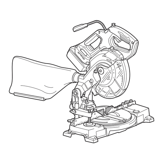
PARTS DESCRIPTION Lock-off button Switch trigger Handle Blade case Blade Blade guard Sub-fence Small sub-fence Base Turn base Guide fence Vertical vice Dust bag Dust nozzle Center cover 7 ENGLISH... -
Page 8: Installation
Lamp Battery cartridge Hex wrench Release lever Lever (for bevel angle Kerf board Lower limit adjusting bolt Lamp switch adjustment) Laser switch INSTALLATION Bench mounting WARNING: Ensure that the tool does not move on the supporting surface. Movement of the miter saw on the supporting surface while cutting may result in loss of control and serious personal injury. -
Page 9: Functional Description
Tool / battery protection system FUNCTIONAL DESCRIPTION The tool is equipped with a tool/battery protection sys- tem. This system automatically cuts off power to the motor to extend tool and battery life. The tool will auto- WARNING: matically stop during operation if the tool or battery is Always be sure that the tool is placed under one of the following conditions: switched off and the battery cartridge is removed before adjusting or checking the functions on Overload protection the tool. - Page 10 When you pull the switch trigger, the battery indicator NOTE: Depending on the conditions of use and the indicates the remaining battery capacity. ambient temperature, the indication may differ slightly from the actual capacity. Battery indicator status Remaining battery Automatic speed change function capacity Blinking 50% to 100%...
-
Page 11: Blade Guard
WARNING: Do not remove spring holding removed guard may result in serious personal injury. blade guard. If guard becomes damaged in course of time or UV light exposure, contact a Makita ser- CAUTION: Always maintain the blade guard vice center for replacement. DO NOT DEFEAT OR in good condition for safe operation. Stop the REMOVE GUARD. - Page 12 ► 1 . Guide fence ► 1 . Saw blade 2. Blade teeth 3. Kerf board 4. Left bevel cut 5. Straight cut Rotate the blade by hand while holding the handle all the way down to be sure that the blade does not Tighten the screws (do not tighten firmly).
-
Page 13: Adjusting The Bevel Angle
Loosen the fixing screw counterclockwise. Adjust the angle of the turn base. Use the pointer and the miter scale as a guide. Tighten the fixing screw clockwise firmly. CAUTION: After changing the miter angle, always secure the turn base by tightening the fixing screw firmly. NOTICE: When turning the turn base, be sure to raise the handle fully. Adjusting the bevel angle ► 1 . - Page 14 ► 1 . Release button ► 1 . Lever 2. Release lever Turn the lever upward firmly to secure the saw CAUTION: After changing the bevel angle, head. always secure the saw head by turning the lever upward firmly. Adjusting the lever position NOTICE: When tilting the saw blade, be sure the If the lever does not provide full tightening in course of handle is fully raised.
-
Page 15: Switch Action
BEFORE further usage. CAUTION: Do not look in the light or see the WARNING: source of light directly. - Page 16 Aligning the laser line Laser beam action Align the cutting line on your workpiece with the laser line. CAUTION: Never look into the laser beam. Direct laser beam may injure your eyes. To turn on the laser beam, press the upper position (I) of the switch. To turn off the laser beam, press the lower position (0) of the switch. A) When you want to obtain the correct size on the left side of workpiece, shift the laser line to the left of the blade. B) When you want to obtain the correct size on the right side of workpiece, shift the laser line to the right of the blade.
- Page 17 CAUTION: Use only the Makita hex wrench provided to install or remove the blade. Failure to do so may result in overtightening or insufficient tightening of the hex socket bolt. This could cause an injury.
- Page 18 For tool with the ring ► 1 . Saw blade 2. Arrow ► 1 . Outer flange 2. Saw blade 3. Inner flange 4. Hex Install the outer flange and hex socket bolt, and socket bolt (left-handed) 5. Ring 6. Spindle then use the hex wrench to tighten the hex socket bolt (left-handed) of the spindle securely counterclockwise WARNING: If the ring is needed to mount the while pressing the shaft lock.
-
Page 19: Securing Workpiece
Dust bag The use of the dust bag makes cutting operations cleaner and dust collection easier. To attach the dust bag, fit it onto the dust nozzle. When the dust bag is about half full, remove the dust bag from the tool and pull the fastener out. Empty the dust bag of its contents, tapping it lightly so as to remove particles adhering to the insides which might hamper further collection. -
Page 20: Operation
Attaching the shoulder strap Press cutting (cutting small workpieces) Optional accessory CAUTION: Be sure to remove the shoulder strap before operating the tool. The shoulder strap may be entangled and cause injury. CAUTION: Be sure to attach the hooks of the shoulder strap to the tool securely. -
Page 21: Compound Cutting
When securing aluminum extrusions, use spacer blocks or pieces of scrap as shown in the figure to prevent deformation of the aluminum. Use a cutting lubricant when cutting the aluminum extrusion to prevent build-up of the aluminum material on the blade. CAUTION: Never attempt to cut thick or round aluminum extrusions. Thick aluminum extrusions may come loose during operation and round alumi- num extrusions cannot be secured firmly with this tool. -
Page 22: Adjusting The Cutting Angle
► 1 . Guide fence 2. Hex socket bolt maintenance. NOTICE: Never use gasoline, benzine, thinner, alcohol or the like. Discoloration, deformation or cracks may result. To maintain product SAFETY and RELIABILITY, repairs, any other maintenance or adjustment should be performed by Makita Authorized or Factory Service Centers, always using Makita replacement parts. ► 1 . Guide fence 2. Hex socket bolt 22 ENGLISH... -
Page 23: Bevel Angle
Lower the handle fully and lock it in the lowered position by pushing in the stopper pin. Adjust the guide fence until it makes a perpendic- ular angle with the blade using a triangular rule, try- square, etc. Then securely tighten the hex socket bolt on the guide fence. ► 1 . Adjusting bolt 2. Lever Turn the 0° bevel angle adjusting bolt clockwise carefully until the side of the blade makes a perpendic- ular angle with the top surface of the turn base. - Page 24 Make sure that the pointer on the arm indicates NOTICE: 45° on the bevel scale. If the pointer does not indicate Have the tool repaired by a Makita 45°, turn the left 45° bevel angle adjusting bolt on the authorized service center for any failure on the right side of the arm until the pointer indicates 45°.
-
Page 25: After Use
Adjusting the laser line on the left side of the blade Cleaning the laser light lens The laser light becomes hard to see as the lens for the laser light gets dirty. Clean the lens for laser light periodically. Remove the battery cartridge. Loosen the screw and pull out the lens. Clean the lens gently with a damp soft cloth. -
Page 26: Optional Accessories
OPTIONAL ACCESSORIES WARNING: These Makita accessories or attach- ments are recommended for use with your Makita tool specified in this manual. The use of any other accesso- ries or attachments may result in serious personal injury. WARNING: Only use the Makita accessory or attachment for its stated purpose. Misuse of an acces- sory or attachment may result in serious personal injury. If you need any assistance for more details regarding these accessories, ask your local Makita Service Center. - Page 28 Makita Europe N.V. Jan-Baptist Vinkstraat 2, 3070 Kortenberg, Belgium Makita Corporation 3-11-8, Sumiyoshi-cho, Anjo, Aichi 446-8502 Japan 885605-221 www.makita.com 20170520...
Need help?
Do you have a question about the DLS600 and is the answer not in the manual?
Questions and answers