Sign In
Upload
Download
Table of Contents
Contents
Add to my manuals
Delete from my manuals
Share
URL of this page:
HTML Link:
Bookmark this page
Add
Manual will be automatically added to "My Manuals"
Print this page
×
Bookmark added
×
Added to my manuals
Manuals
Brands
Dosmatic Manuals
Laboratory Equipment
MiniDos 0.4
Operating instructions manual
Dosmatic MiniDos 0.4 Operating Instructions Manual
0.4%, 2.5%, 5%, 10%, 20%
Hide thumbs
1
Table Of Contents
2
3
4
5
6
7
8
9
10
11
12
13
14
15
16
17
18
19
20
21
22
23
24
25
26
27
page
of
27
Go
/
27
Contents
Table of Contents
Troubleshooting
Bookmarks
Advertisement
Table of Contents
1
Table of Contents
2
Introduction
3
Safety
4
Installation
5
Installation
6
Operation
7
Maintenance
8
Trouble Shooting
9
Specifications
10
Wear Parts Kits
11
Wear Parts Kits
12
Warranty
Download this manual
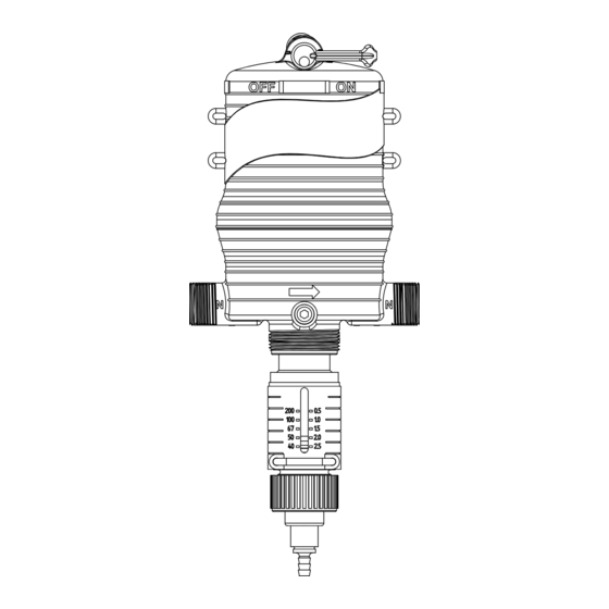
MINIDOS
®
Installation & Operating Instructions
Model No.
MiniDos - 0.4%, 2.5%, 5%, 10%, 20%
1
Certified ISO 9001:2000 Quality Management System
Table of
Contents
Previous
Page
Next
Page
1
2
3
4
5
Advertisement
Table of Contents
Need help?
Do you have a question about the MiniDos 0.4 and is the answer not in the manual?
Ask a question
Questions and answers
Related Manuals for Dosmatic MiniDos 0.4
Laboratory Equipment Dosmatic Superdos 30 Operating Manual
(68 pages)
Laboratory Equipment DOSMATIC SuperDos 45 Installation & Operating Instructions Manual
0.4%, 2.5%, 5% (23 pages)
Laboratory Equipment Dosmatic Advantage A20-10% Installation & Operating Instructions Manual
(32 pages)
Laboratory Equipment Dosmatic SUPERDOS 20 Installation & Operating Instructions Manual
(22 pages)
Laboratory Equipment DOSMATIC Superdos 20 Series Operating Manual
(76 pages)
Laboratory Equipment Dosmatic MicroDos II Operating Manual
(37 pages)
Laboratory Equipment DOSMATIC Superdos 45 0.3% PAA Operating Manual
(66 pages)
This manual is also suitable for:
Minidos 5
Minidos 20
Minidos 2.5
Minidos 10
Table of Contents
Print
Rename the bookmark
Delete bookmark?
Delete from my manuals?
Login
Sign In
OR
Sign in with Facebook
Sign in with Google
Upload manual
Upload from disk
Upload from URL


Need help?
Do you have a question about the MiniDos 0.4 and is the answer not in the manual?
Questions and answers