Jaga BRIZA 12 Installation Instructions Manual
Stand alone / built-in
Hide thumbs
Also See for BRIZA 12:
- Manual (56 pages) ,
- Installation instructions manual (52 pages) ,
- Installation instructions manual (48 pages)

Related Manuals for Jaga BRIZA 12


Summary of Contents for Jaga BRIZA 12
- Page 1 BRIZA 12: STAND ALONE / BUILT-IN INSTALLATION INSTRUCTIONS: BRIZA12 041-055 / H038-H052: WALL- AND CEILING...
-
Page 2: Table Of Contents
INSTRUCTIONS TO DISMANTLE THE UNIT .............. 97 Jaga N.V. Verbindingslaan 16 B-3590 Diepenbeek +32 (0)11 29 41 11 info@jaga.be www.jaga.be Jaga reserves the right to change product specification at any time in line with our policy of continuous improvement and innovation. - Page 3 Important info The BRIZA 12 must be installed and connected by a certified installer in accordance with these installation instructions and the applicable local regulations. Read this manual carefully to ensure the device will be installed properly. Please follow these instruc- tions and file them somewhere safe! The device must always be accessible so maintenance can be performed.
-
Page 4: Declaration Of Conformity
DECLARATION OF CONFORMITY JAGA N.V. - Verbindingslaan 16 - B 3590, declares under its sole responsibility that the CEO JAGA N.V. product to which this declaration relates: BRIZA 12, BRIZA 22 Jan Kriekels is in conformity with the following standards or documents provided that these are used in... -
Page 5: Warnings And Safety
WARNINGS AND SAFETY HANDLING GUIDELINES: DANGER! Movement of the unit must be performed with care, in order to avoid damage to the external struc- ture and to the internal mechanical and electrical components. Also make sure that there are no obstacles or people along the route, in order to prevent the risk of impact, crushing or tipping the lifting device. -
Page 6: General Information
GENERAL INFORMATION Device description: Jaga Briza 12 are fan coils for the treatment of air in indoor environments. Declared conditions of use: The unit is not designed to be installed in wet areas (IEC EN 60335-2-40). DANGER! the unit is only to be installed in domestic or similar environments. -
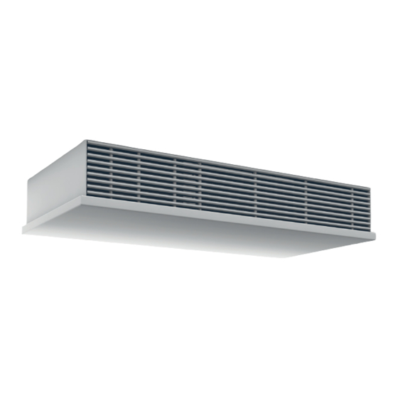
Page 7: Jaga Briza 12 - Overview Parts
JAGA BRIZA 12 - OVERVIEW PARTS CEILING Dynamic Low-H2O hydrophilic heat exchanger Hydraulic connection 2-pipe 3/4"G (Eurocone) Dynamic outlet grille* Condensate drain (Option for ceiling built-in) Condensate drain (ceiling built-in) Electrical connection The direction of the aire flow is determined by the shape of the grille fins. -
Page 8: Technical Data
TECHNICAL DATA WALL- AND CEILING UNIT: BRIZA 041 Dimensions 17.7 13.7 35.2 20.8 min. 10 A: Supply R: Return MODEL L (CM) 13.7 17.7 *Condensate drain pan: standard for wall units / Option for ceiling unit WALL- AND CEILING UNIT: BRIZA 041 - HYDRAULIC CONNECTIONS 2-PIPE EN 4-PIPE 48.2 Dimensions 12.5... - Page 9 WALL- AND CEILING UNIT BUILT-IN: BRIZA 038 Dimensions L-2.5 11.7 35.2 20.8 min. 10 *: drill dimensions A: Supply R: Return MODEL L (CM) 50,5 70,5 100,5 120,5 11.7 L-2.5 *Condensate drain pan: standard for wall units / Option for ceiling unit WALL- AND CEILING UNIT BUILT-IN: BRIZA 038 - HYDRAULIC CONNECTIONS 2-PIPE EN 4-PIPE Dimensions 48.2...
- Page 10 min. 10 WALL- AND CEILING UNIT: BRIZA 055 Dimensions 13.7 17.7 48.2 20.8 12.5 12.5 min. 10 A: Supply R: Return MODEL L (CM) *Condensate drain pan: standard for wall units / Option for ceiling unit WALL- AND CEILING UNIT: BRIZA 055 - HYDRAULIC CONNECTIONS 2-PIPE EN 4-PIPE Dimensions 2.75 Stop hydraulic...
- Page 11 min. 10 WALL- AND CEILING UNIT BUILT-IN: BRIZA 052 Dimensions 11.7 L-2.5 48.2 20.8 min. 10 A: Supply *: boorafmetingen R: Return MODEL L (CM) 50,5 70,5 100,5 120,5 *Condensate drain pan: standard for wall units / Option for ceiling unit WALL- AND CEILING UNIT BUILT-IN: BRIZA 052 - HYDRAULIC CONNECTIONS 2-PIPE EN 4-PIPE Dimensions 2.75...
- Page 12 max. 250 cm max. 250 cm MOUNTING DIMENSIONS BUILT-IN BRIZA 038 EN BRIZA 052 WALL Dimensions Respect the free space around the unit as shown: 16 / 19 16 / 19 ≥15 ≥15 ≥15 ≥15 ≥15 ≥15 ≥10 ≥10 * according the ordered corner piece CEILING Dimensions Respect the free space around the unit as shown:...
- Page 13 OPERATING LIMITS If the appliance is supplied with chilled water, the condensation forming on the heat exchanger will be drained via the condensation drain connection. At very low chilled water temperature and very high humidity, condensation may form on compo- nents other than the heat exchanger.
-
Page 14: Installation
INSTALLATION DANGER! – installation must only be carried out by certified technicians. Incorrect installation could cause the unit to run badly, with a consequent deterioration in performance. – the unit must be installed according to national or local standards in force at the time of installation. Always use personal protective equipment. - Page 15 Remove the grille. Only for ceiling surface mounted: unscrew the grille security slide the clamp plates to the outer side of the grille. Remove the screws above and below the unit. Remove the casing. Further technical installation and connection (s) is identical for all Briza Built-In and Surface units. –...
- Page 16 Mark the fastening points, using those on the unit or according to The type of wall determines what type of screw or plug should be the dimensions specified on page 82 and 84 in this guide. used. For installation on drywall: make sure that the mounting holes line up with supporting studs.
- Page 17 3 cm/m 3 cm/m Wall Ceiling Setting up the condensate drain: The condensation drainage system must be set up with an adequate inclination to make sure the water drains properly. When not using the condensate drain pan, the outlet duct must be connected directly to the conden- sation collection.
- Page 18 The electrical connection of the unit must be carried out by qualified personnel, in compliance with the regulations applicable in the country where the unit is installed. Non-conforming electrical con- nections releases Jaga N.V. from liability concerning damage to objects and persons. DANGER! –...
- Page 19 OPTION: ELECTRICAL CONNECTION TO HOME AUTOMATION - 0...10V Briza +24 V 0...10 V + 0...10V 0..10V Domotica CODE: 7990.050/51/52 Netvoeding / Alimentation DC LO Netzteil / Power supply DC ON 24 V 230 V / 115 V Units with casing: Place the grill Position the casing and attach the screw above and below the unit The direction of the airflow is determined by the shape of the...
-
Page 20: Start Up
START UP IMPORTANT! Start-up and Commissioning of the unit (where applicable) must be carried out by skilled personnel, qualified to work on this type of product. DANGER! Before starting up, make sure the installation and electrical connections have been carried out in compliance with the instructions in this manual. -
Page 21: Option Valve Sets
↑ ↑ code sleeve couplings M24 sleeve couplings for M24 male threaded JAGA TWO-WAY VALVE + MOTOR 230 V – only for mounting on the distributor – with position indicator (open / close) – sleeve couplings to be provided by the installer CODE 7990.409... -
Page 22: Option Roomthermostats
– 3 programmable zones (5.1 + 1) – 0-10V DC output – mounting on wall mounting box or directly on the wall key card / window contact JFCC.001 (ONLY TO ORDER TOGETHER WITH THE DEVICE. EX FACTORY (CONTACT JAGA FOR MORE INFO).) -
Page 23: Maintenance
MAINTENANCE DANGER! – maintenance must only be carried out by qualified technicians, qualified to work on air-conditioning and refrigeration systems. Use suitable work gloves – do not insert sharp objects through the air flow or intake grilles – the unit has sharp edges; use gloves during maintenance! DANGER! Always use the mains switch to isolate the unit from the mains before carrying out any maintenance work on the unit, even if it is for inspection purposes only. -
Page 24: Warranty
– equipment that is built in, in a way that it cannot be reached normally. If you have any questions or complaints, please contact your supplier or installer. The copyright of these instructions is the property of the company Jaga n.v INSTRUCTIONS TO DISMANTLE THE UNIT SAFEGUARD THE ENVIROMENT Jaga N.V. - Page 25 NOTA 27200.23700032...
- Page 26 NOTA...
-
Page 27: Verbindingslaan
Jaga N.V., Verbindingslaan z/n, B-3590 Diepenbeek Tel.: +32 (0)11 29 41 11, Fax: +32 (0)11 32 35 78, info@jaga.be - www.jaga.be 27200.23700032 - oktober 11, 2018 3:35 PM - Jaga N.V.