
Related Manuals for mensor CPC6050


Summary of Contents for mensor CPC6050
- Page 1 Operating Instructions Modular Pressure Controller CPC6050 Modular Pressure Controller CPC6050 PN 0019108001D • 11/2016...
- Page 2 This Caution symbol indicates danger for the system and material if the respective safety precautions are not taken. Caution This Notice symbol does not indicate safety notices but information for a better understanding of the facts. Notice Operating Instructions - CPC6050...
-
Page 3: Table Of Contents
5.1 Unpacking the Instrument 5.2 Dimensions (mm)/ inches 5.3 Mounting 5.4 Rear Panel 5.4.1 Pressure Connections 5.4.2 Supply Port 5.4.3 Exhaust Port 5.4.4 Vent Port 5.4.5 Measure / Control Port 5.4.6 Reference Port 5.4.7 Barometric Reference Port Operating Instructions - CPC6050... - Page 4 Control Behavior for Pump Module 6.4.3.4 Rate Setpoint 6.4.3.5 Stability Parameters 6.4.3.6 Control Volume 6.4.3.7 Control Limits 6.4.3.8 Vent Rate 6.4.3.9 Rate Stability Parameters 6.4.3.10 Detection Flags 6.4.4 Display Settings Application 6.4.4.1 Channel Selection 6.4.4.2 Reading Filter 6.4.4.3 Reading Resolution Operating Instructions - CPC6050...
- Page 5 7.8 Command and Query Format 7.9 Command Set Definitions 7.10 Output Formats 7.11 CPC6050 Commands and Queries 7.11.1 Units Command Syntax for Measurement Units 7.11.2 CPC6050 Error Codes 7.11.3 SCPI Commands and Queries 7.11.4 SCPI Commands Error Messages and Error Codes 7.11.5 GPIB Capability Codes...
- Page 6 8.8.2 Block and Bleed Valve (part number: 0019012001) 8.9 Pressure Booster 9. Maintenance 9.1 Beyond the Warranty 9.2 Spare Parts 9.3 Transducer Removal 9.3.2.1 Barometric Reference Removal 10. Calibration 10.1 Calibration Services by Mensor or WIKA worldwide 10.2 Environment 10.3 Pressure Standards 10.4 Media 10.5 Setup 10.6 Calibration Data 10.7...
-
Page 7: General Information
Mensor, this warranty does not apply. The judgment of Mensor will be final as to all matters con- cerning condition of the product, the cause and nature of a defect, and the necessity or manner of repair. -
Page 8: Trademarks And Copyrights
Notice Mensor and its suppliers shall not be held to any liability for any damages suffered or incurred by the end user (including, but not limited to, general, special, consequential or incidental damages including dam- ages for loss of business profits, business interruption, loss of business information and the like), arising from or in connection with the delivery, use or performance of the software program. -
Page 9: Safety Notices
Extreme care must be taken with pressure connections when using hazardous or toxic media. Repairs must only be performed by authorized service personnel. Additional safety notices are found throughout this manual. Notice Operating Instructions - CPC6050... -
Page 10: Warnings And Caution Notices
CAUTION: ESD PROTECTION REQUIRED. The proper use of grounded work surfaces and personal wrist straps are required when coming into contact with exposed circuits (printed circuit boards) to prevent static discharge to sensitive electronic components. Additional Warning and Caution notices are found throughout this manual. Operating Instructions - CPC6050... -
Page 11: General Description
• 0.01% Intelliscale-50 accuracy. • Easily removable transducers from the front of the CPC6050 without any external tools. This facilitates “out of instrument” recalibration of individual transducers using the optional calibration sled. • An optional removable / interchangeable internal high accuracy barometric reference transducer providing gauge pressure emulation for absolute ranges and absolute pressure emulation for gauge ranges. -
Page 12: Turning On
CPC6050 Turning On You can confirm that your CPC6050 is operational right now. Apply power to the power connector on the rear of the instrument with the included power cord, remove any plastic plugs from the rear panel pres- sure ports, and press the power switch to ON. The system will go through an initialization process, which takes about 30 seconds, and then a display will appear similar to the screen shown below. -
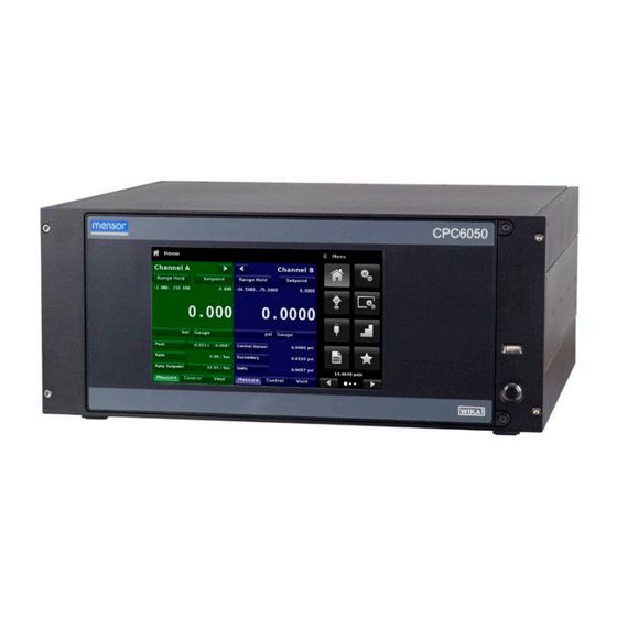
Page 13: Front Panel
CPC6050 Front Panel The CPC6050 front panel includes an 8.9” color LCD display with touch screen. Operator input is ac- complished by pressing the words or symbols and the App icons presented on the display. There is a single discrete on/off button and a USB on the right hand side. The front panel is hinged for easy access to remove or replace the transducers inside. -
Page 14: Display
Operating Screen Settings Apps Buttons, Labels and Windows: The CPC6050 touch screen has many buttons with relevant graphic icons or text which, when touched, will open a related window where changes can be made or informa- tion viewed. Some of these buttons will toggle from one state to another, others present choices or dis- play a numerical data entry screen. -
Page 15: Chassis Assembly
Each transducer includes its own on-board compensation and calibration data so that any transducer can be replaced in the instrument without requiring a recalibration. Figure 3.5.1 - SVR Module Pump Module Operating Instructions - CPC6050... -
Page 16: Electrical Block Diagram
Modular Pressure Controller CPC6050 Electrical Block Diagram Figure 3.6 – Electrical Block Diagram Operating Instructions - CPC6050... -
Page 17: Specifications
ISO Guide to the Expression of Uncertainty in Measurement (GUM). The calibration program at Mensor is accredited by the American Association of Laboratory Accreditation (A2LA) as complying with both the ISO/IEC 17025:2005 and the ANSI/NCSL Z540-1-1994 standards. If there is an exception to the requirements and recommendations of Z540 during a calibration the excep- tion is noted on the individual calibration certificate. -
Page 18: Base Instrument
50 ... 300 ccm Communication Interface Standard: Ethernet, IEEE-488, USB, RS-232. Command sets Mensor, WIKA SCPI, others optional Response time approx. 100 ms Internal program up to 7 sequences with up to 99 steps each 8) Represents LPSVR, MPSVR, HPSVR and EPSVR... -
Page 19: Approvals And Certificates
EPSVR MODULE 0 ... 11 bar (0 ... 165 psi) 1) Mixing of absolute pressure and gauge pressure transducers in a module is not possible. 2) Smallest recommendable transducer range For controlling absolute pressure a vacuum pump connected at the Exhaust port is required. Operating Instructions - CPC6050... -
Page 20: Installation
• CPC6050 Modular Pressure Controller • Power Cord • Fitting adapters ordered • Any accessories ordered • An envelope containing the calibration certificate(s) • A Quick Start Guide for all Mensor products • A USB drive containing all Mensor manuals Operating Instructions - CPC6050... -
Page 21: Dimensions (Mm)/ Inches
Rear Panel (10-32 UNF) IEEE-488 Digital I/O Exhaust Ports (7/16-20 UNF) RS-232 Supply Ports (7/16-20 UNF) Ethernet Port Measure / Control Ports USB (device) (7/16-20 UNF) Reference Ports (7/16-20 UNF) Power Supply USB (host) Vents (ATM) Operating Instructions - CPC6050... -
Page 22: Mounting
CPC6050 (see Section 5.2 Dimensions and Section 8, Options). The special transducers used in the CPC6050 are relatively insensitive to tilt and vibration. However to further assure stability and accuracy, avoid mounting the instrument on surfaces subject to excessive mo- tor or machinery vibration. -
Page 23: Supply Port
Do not position the equipment so that it is difficult to remove the power cord. The instrument is not intended for connection of long-distance lines, i.e. lines within a building that are longer than 30 m, or that leave the building (including lines of outdoor installations). Operating Instructions - CPC6050... -
Page 24: Local Operation And Setup
3 of the 5 available auxiliary displays (Peak, Rate, Rate Setpoint, Uncertainty or Units) will appear in the Home App if activated. All of the CPC6050 screen features are de- scribed in more detail throughout this manual. The active App is represented with a light gray background color compared to the other Apps. -
Page 25: Initial Setup
App buttons. This gives access to the second page of the App selection area. Press the Infor- mation App button [ ]to display Mensor contact, installed transducers, installed regulator along with instrument and software version information Figure 6.2.1 - Information 6.2.2 Language Selection... -
Page 26: Application Selection And Parameter Inputs
Menu button [ ] above the input area. The purpose and use of each selection and menu is intuitively apparent and will become second nature with minimal exposure to the menu structure. Menu Button Input Title App Title Operating Instructions - CPC6050... -
Page 27: Applications
If a barometric reference is installed, the Pressure Type button, described below, will toggle from Gauge to Absolute mode when pressed. Channel Expand Button Figure 6.4.1-A Basic Home App Figure 6.4.1-B – Single Channel Display Figure 6.4.1-C – Pressure Units Operating Instructions - CPC6050... -
Page 28: Range Hold / Autorange
These methods can be accessed by the user by pressing the “Setpoint” button and the various setpoint entry methods can be navigated with the Next Page [ and Previous Page [ ] buttons. Setpoint button Figure 6.4.1.2 – Setpoint Button Operating Instructions - CPC6050... - Page 29 If the Enter [ ] button is pressed the newly entered value will register as a new setpoint value on the Home Screen rather than a step value. Figure 6.4.1.2.2 - Numeric Keypad with Step Increments Operating Instructions - CPC6050...
- Page 30 1. The right most digit in the Digital Step corresponds to the lease significant digit of the setpoint. Each digit of the setpoint can then be increased or decreased by pressing the Up [ or Down [ ] button. Figure 6.4.1.2.4 - Digital Step Entry Operating Instructions - CPC6050...
-
Page 31: Units And Pressure Type
6.4.1.2.5 Program Data Entry The fifth entry method is through the automated Programs stored in the CPC6050 memory. The Program Player allows the user to select one of the stored Programs and use it for setpoint entry. A Program can... -
Page 32: Auxiliary Displays
Pressing any of these units will change the auxiliary units to that chosen unit. Digital I/O: Displays the current state of digital inputs and outputs per channel as "1" for high and "0" for Barometer: Dispays the reading of the optional barometric reference in current pressure units Operating Instructions - CPC6050... -
Page 33: Zero Button
Figure 6.4.1.6 - Zero Button, Gauge - Absolute The background color of the zero button will momentarily change to a lighter color as the zero calibration is performed then will revert back to a darker color when complete. Operating Instructions - CPC6050... -
Page 34: Tare Button
Pressing the tare button again will deactivate the tare and change the pressure indication back to the reading corresponding to the calibrated output of the transducer. An active tare will revert to a deacti- vated state after a power cycle. Operating Instructions - CPC6050... -
Page 35: Operating Mode Selection
CPC6050 6.4.1.8 Operating Mode Selection The operating modes are permanently displayed on bottom of the Home App. The CPC6050 has three operating modes: Measure, Control and Vent. After the system has switched on, the instrument will automatically be placed in Measure mode. The user can switch from one mode to the other by using the... -
Page 36: Settings Application
(.) to a comma (,) depending on the language chosen. More languages can be ac- cessed by navigating to the next page of the language selection menu on the right side of the screen. Figure 6.4.2.1 - Languages Operating Instructions - CPC6050... -
Page 37: Brightness
Figure 6.4.2.2 - Brightness 6.4.2.3 Volume The Volume setting provides a way to turn on or off the touch screen audio feedback. Figure 6.4.2.3 - Volume Operating Instructions - CPC6050... -
Page 38: User Base Units / Base Units Multiplier
Any of these units can be chosen from this list for the barometric readout. The barometric pressure readout can be seen on the bottom right of the Home App. Figure 6.4.2.5 - Barometer units Operating Instructions - CPC6050... -
Page 39: Instrument Mode
To reload a saved configuration at a later time, go to Settings-Configuration and press the numbered configuration button corresponding to the saved configuration and then press the “Load” but- ton. Figure 6.4.2.7 - Configuration The instrument default configuration can be activated simply by pressing the “Default” Button. Operating Instructions - CPC6050... -
Page 40: Control Settings Application
The Control Behavior can be changed using the sliding scale. This will change the control mode to “Custom”. Figure 6.4.3.1 shows the sliding bar to adjust control behavior. Figure 6.4.3.1 - Control Behavior SVR Module Operating Instructions - CPC6050... -
Page 41: External Supply For Pump Module
The Control Behavior for the Pump Module only differs from the SVR Module in that it does not have the preset buttons for Precision, High Speed and Custom. Otherwise, its function is identical to that of the SVR Module explained in Section 6.4.3.1 above. Figure 6.4.3.3 - Control Behavior for Pump Module Operating Instructions - CPC6050... -
Page 42: Rate Setpoint
The Rate Setpoint (SVR Module only) button allows the user to set the rate of pressure change when the CPC6050 is controlling up or down to a setpoint (figure 6.4.3.4). The rate is limited from 0.001% to 10% of span of active range of the transducer / second. -
Page 43: Control Volume
The Control Volume button (SVR Module and Pump Module) in the Control Settings App allows the user to set the control pressure volume in cubic centimeters (cc). The CPC6050 is capable of automatically identifying the control pressure volume and adjusting the control parameters based on it. By default this button is set on “Auto”. -
Page 44: Vent Rate
The Rate Stable Delay button lets the user add a desired delay until the control rate is considered stable while being in the rate stable window. Stability Parameters Figure - 6.4.3.9 Rate Stability Parameters Operating Instructions - CPC6050... -
Page 45: Detection Flags
6.4.3.10 Detection Flags The CPC6050 is equipped with three detection flags (SVR Module only) that can be enabled or disabled by the user as needed. These detection flags appear in the Control Settings App. The primary purpose of these detection flags is to protect the instrument and to ensure desired operation. Each of these flags can be turned “On”... -
Page 46: Display Settings Application
To set the channel’s display parameters, the control channel must be selected. Display parameters are iden- tical for all channels but can be set differently in each channel. Figure 6.4.4.1 shows three displays where channel “A” “B” and Delta have been selected. Figure 6.4.4.1 - Channel Selection Operating Instructions - CPC6050... -
Page 47: Reading Filter
The Resolution of the displayed pressure value for each Channel can be set in the Display Settings Ap- plication using the resolution Parameter. The resolution can be set to 4, 5 or 6 digits. Figure 6.4.4.3 - Reading Resolution Operating Instructions - CPC6050... -
Page 48: Cal Functions
Channel A - Channel B (A-B), or Channel B - Channel A (B-A). The Delta Screen in the Home App will display a reading resulting from the mathematical equation chosen in this screen. Figure 6.4.4.5 - Delta Function Operating Instructions - CPC6050... -
Page 49: Remote Application
Figure 6.4.5 - Remote Application 6.4.5.1 Remote Command Set The remote command set parameter provides a choice of the Mensor command set, the WIKA SCPI command set or DPI5xx. All sets of commands are listed in Section 7, Remote Operation. -
Page 50: Remote Communication Settings
If a DHCP server is not found, an error will be indicated. If DHCP is enabled, the IP address, Netmask and Gateway are greyed out and locked, these are controlled by the DHCP server. Figure 6.4.5.2 - Remote Communication Settings Operating Instructions - CPC6050... -
Page 51: Step Settings Application
Range buttons (figure 6.4.6-A) and enter the values. These ranges should be within the maxi- mum range of the primary transducer in the selected channel. CPC6050 automatically switch between Pressure units and Percent of DUT Range values by pressing the units button or the percent button (Figure 6.4.6 - B). -
Page 52: Preset Steps
For example if the user needs 5 distinct points along the DUT range then enter 5 in the numeric keypad and press Enter [ ] button. CPC6050 will create setpoints at 0%, 25%, 50%, 75% and 100% of the DUT range (Figure 6.4.6.1 - A). The user also has the option of changing these percentage values or adding aditional values as needed by clicking on the individual Percentage button on the Step Settings app. -
Page 53: Programs Application
The Programs Application is used to create, view and edit programs that are used to automati- cally run a sequence of commands within the CPC6050. The Programs App screen displays the contents of the first written program in read only mode by default (figure 6.4.7-A). User can load, edit and delete other saved and predefined programs by clicking on the title of the current program and then selecting the desired program sequence from the sidebar (figure 6.4.7-B). - Page 54 Sets the rate setpoint in current units (Numerical Entry) SEQZERO Set the zero for the current active transducer SEQSTART Starts the sequence from the beginning (None) RUNITS Sets the rate denominator time unit (min or sec) Operating Instructions - CPC6050...
-
Page 55: Favorites Application
Figure 6.4.8 - Favorites Application 6.4.9 Information Application The Information Application displays information about the instrument, including: • Mensor address, and email • Model number, serial number and operating software version. • Regulator model number, serial number and software version. -
Page 56: Troubleshooting Application
] will appear in all screens (Figure 6.4.10- A) of the instrument. Pressing this error button from any screen will open the Troubleshoot application where the error can be viewed. Figure 6.4.10-A - Error indication Figure 6.4.10-B - Troubleshoot screen Operating Instructions - CPC6050... -
Page 57: Digital I/O Application
Invert Logic (Yes/No) button. When a digital signal (switch closure) is sent to either of the input terminal on the back panel of the CPC6050, the instrument will perform actions based on the options assigned to the input. -
Page 58: Leak Test Application
Dwell Time, indicating a “passed” test. See Figure 6.4.12-A for examples of a failed and a passed test on channel A. Figure 6.4.12 - Leak Test Figure 6.4.12-A - Leak test fail (left) & Leak test pass (right) Operating Instructions - CPC6050... -
Page 59: Switch Test Application
• Slow Rate: The rate at which the controller will control between the Low Point and the High point. The Switch Test is initiated by pressing the start button. Figure 6.4.13-A – Power Supply Figure 6.4.13-B Operating Instructions - CPC6050... -
Page 60: Burst Test Application
The burst test is initiated by press- ing the Start button. Figure 6.4.14-A and 6.4.14-B show the different status messages during a burst test. Figure 6.4.14-A - Burst Test Figure 6.4.14-B - Burst Test Complete (No Burst) Operating Instructions - CPC6050... -
Page 61: Service Application
Default password is 123456. Enter 123456 and press the check mark [ ] to unlock the Service Application. Figure 6.4.15-B - Service Application (Enter Password) Note: The default Password is 123456. After entering this for the first time, the password can be changed. Operating Instructions - CPC6050... -
Page 62: Unlocked Service Application
The Unlocked Service Application is the access point to all calibration screens described in Section 10 of this manual. Note: Recommended calibration setup and explanation of calibration screen applica- tions is covered in Section 10 of this manual. Operating Instructions - CPC6050... -
Page 63: Remote Operation
Connector Pin Out designation corresponds to numbers on the connector: 1 – Ground 2 – Input #1 3 – Input #2 4 – Input #3 5 – Ground 6 – Output #1 7 – Output #2 8 – Output #3 Operating Instructions - CPC6050... -
Page 64: Remote Operating Parameters
Clear status and error queue *ESE Enable status event *ESE? Returns enable status event value *ESR Event status register *ESR? Returns event status register value *SRE Service request enable *SRE? Returns service request enable value *STB? Returns status byte Operating Instructions - CPC6050... -
Page 65: Ethernet
CAUTION: Please consult your computer resources department prior to connect- ing this instrument to your network to verify there are no conflicts with existing IP addresses. Caution The Ethernet communication port allows the CPC6050 to communicate with computers using 10/100Based-T specifications. Before using Ethernet communication, four parameters must be set up: IP, Netmask, Gateway, and Port. Operating Instructions - CPC6050... -
Page 66: Serial
1 stop bit, no parity, and no echo. If echo is ON, the CPC6050 will immediately echo back characters sent over the serial port. The Serial function allows the user to set the RS-232 serial port settings by selecting from the choices provided: •... -
Page 67: Mensor Command Set
Mensor Command Set This Mensor command set is the default on the CPC6050. For queries (ending with a ?), the Data column represents the response of the CPC6050. All response strings begin with a space character or an “E” rep- resenting that there is an error in the error queue. -
Page 68: Output Formats
Table 7.11 lists all of the current CPC6050 commands and queries. Channel specific commands are sent to only the active channel. See ‘CHAN’ command. Notice Optional emulation modes are available in which a CPC6050 can emulate remote functions of different brands of pressure gauges. Please contact Mensor for more details. Table 7.11 - CPC6050 Commands and Queries Command... - Page 69 Returns reading from barometric transducer or “NO BAROMETER” if one isn’t installed Burst_Detect YES,NO Sets burst detection enable, see Sec- tion 6.4.3.10 Detection Flags. Burst_Detect? <sp>(YES or NO)<cr><lf> Returns whether burst detection is enabled or not Operating Instructions - CPC6050...
- Page 70 <sp>(A, B, or D)<cr><lf> Return the current channel for remote communication Cmdset Mensor, DPI510, DPR60c, SCPI Activates remote command set for instrument emulation modes. Cmdset? <sp><CCCCCC><cr><lf> Returns active command set identifier Control Instrument placed in Control Mode Operating Instructions - CPC6050...
- Page 71 Returns an integer between 0 and 63 mm/dd/yyyy Sets the date of cal for the active transducer. DOC? <sp>mm/dd/yyyy<cr><lf> Returns the date of cal for the active transducer. DOM? <sp>mm/dd/yyyy<cr><lf> Returns the date of manufacture Operating Instructions - CPC6050...
- Page 72 <sp>(YES or NO)<cr><lf> Returns the status of the highspeed mode <sp>MENSOR,CPC6050, Ssssss is the serial number,v.v.vv is ssssss,v.v.vv<cr><lf> the CPC6050 software version. nnn.nnn.nnn.nnn Sets the IP address of the instrument <sp>nnn.nnn.nnn.nnn<cr><lf> Returns the IP address of the instru- ment Keylock...
- Page 73 Returns YES if instrument is in mea- sure. NO if otherwise Meas_Reg ON or OFF Sets the regulation of the pressure across the Measure/Control solenoid, see Section 6.4.3.10 Detection Flags. Meas_Reg? <sp>(YES or NO)<cr><lf> Returns whether measure regulation is enabled Operating Instructions - CPC6050...
- Page 74 {EXTVAC or ATM} Sets the reference type for vacuum pump connected to the reference, or vented to atmosphere. This option is available only on native gauge units. Reference? <sp>{EXTVAC or ATM}<cr><lf> Returns the current reference type. (see Reference) Operating Instructions - CPC6050...
- Page 75 Sets the control setpoint in % of cur- rent range Setptpct Value in % of current range Sets the control setpoint in % of cur- rent range Setptpct? <sp>n.nnnnnE+nn<cr><lf> Returns the current setpoint in % of current range Operating Instructions - CPC6050...
- Page 76 Sparity? <sp>CCCC<cr><lf> Returns the serial parity Srqmask Stable,Error or both Sets the CPC6050 to issue a service request(SRQ) over the IEEE when the pressure control is stable, or an error occurs. These are 80 hex and 40 hex respectively. Srqmask? <sp>{string}<cr><lf>...
- Page 77 ON / OFF Tares the reading to zero Tare? <sp> n.nnnnnE+nn <cr><lf> Returns value of Tare Transfer_factory_to_ Copy factory linearity coefficients to linearity customer Units Units code or text in table below Sets the instrument engineering units Operating Instructions - CPC6050...
- Page 78 Returns the exponential filter window for the active transducer Zero Desired pressure or ? Sets zero to set pressure or for ?, clears previous value. CALDISABLE must be OFF/NO. Zero? <sp>n.nnnnnE+nn<cr><lf> Returns zero offset for active trans- ducer Operating Instructions - CPC6050...
-
Page 79: Units Command Syntax For Measurement Units
@ 0°C Metric tons per square inch Imperial hectapascals Metric megapascals Metric millimeters of water @ 20°C MMH2O Metric centimeters of water @ 20C CMH2O Metric meters of water @ 20°C MH2O Metric Operating Instructions - CPC6050... -
Page 80: Cpc6050 Error Codes
Modular Pressure Controller CPC6050 7.11.2 CPC6050 Error Codes Code Serial Poll Byte Description Error String Returned No errors NO ERRORS Parameter error EGPIB PARAMETER ERROR: String that was sent Syntax error EGPIB SYNTAX ERROR: String that was sent 7.11.3 SCPI Commands and Queries... - Page 81 Not used, does not cause an error, dose not return a response :ERRor[:NEXT]? Returns error code, description :KLOCk ON | OFF | 1 | 0 Sets the keylock state :PRESet Load known state values :SAVe No function (not needed) :VERSion? Returns SCPI version 1994.0 Operating Instructions - CPC6050...
- Page 82 :MODE MEASure | CONTrol | VENT Sets the mode indicated :MODE? Returns the mode string :STABle? Returns 1 if stable 0 if not :AUTOvent ON | OFF | 1 | 0 Autovent is always true on CPC6050 Operating Instructions - CPC6050...
- Page 83 Set the minimum control limit :LOWer? Set the minimum control limit :UPPer<n> Set the maximum control limit :UPPer? Set the maximum control limit :SYSTem :DETECT SLOW | FAST | CANCEL Not used, kept for backwards compatibility :DETECT? Returns “0” Operating Instructions - CPC6050...
-
Page 84: Scpi Commands Error Messages And Error Codes
Group Execute Trigger: When this message is received, the CPC6050 will save the current read- ings until the next time it is addressed as a talker. Go To Local: A GTL message will cause the CPC6050 to return to local operation and unlock the keyboard. -
Page 85: Usb Software Upgrade
Mensor website onto a USB device. The instrument software is device specific and the software for any other instrument apart from the CPC6050 is not accepted by the instrument. The user can then plug the USB device to the USB port on the front panel of the instrument for an easy upgrade. The instru- ment recognizes this device by displaying a USB icon on the top bar of the screen (figure 7.12). -
Page 86: Options
When configured with four transducers that have contiguous ranges, this Single Output Auto Range Version of the CPC6050 can calibrate a sensor over a wide range with the highest possible accuracy and test uncertainty ratio. -
Page 87: Single Output Auto Range Rear Panel
8.2.1 Single Output / Dual Channel Home App The Home App for the CPC6050 Single Output / Dual Channel version provides a place for the operator to switch between Channel A and Channel B. When switching from one channel to another, the instru- ment will vent the active channel before making the new channel active. -
Page 88: Single Output / Dual Channel Rear Panel
Plugged ports, do not remove Barometric Reference The CPC6050 can be ordered with a barometric reference transducer. It is a very stable, absolute pres- sure transducer, used to accurately measure local atmospheric pressure. It is used to display the baro- metric pressure (reading appears on the bottom right side of the display) or as a barometric reference for gauge or absolute emulation. -
Page 89: Emulation Mode Accuracy
If the add-on transducer is of a higher full scale range than the existing primary transducer, then this newer transducer becomes the Primary, and the existing transducer must be moved to the Secondary Transducer slot. For complete installation instructions see Section 9.3 ,Transducer Removal. Operating Instructions - CPC6050... -
Page 90: Rack Mount Kit
Modular Pressure Controller CPC6050 Rack Mount Kit A rack mount kit allows the customer to install a CPC6050 into a standard 19” instrument rack. It includes mounting tabs, rack rail sides and a selectable adapter kit. Figure 8.5 - Rack Mount Kit Fittings A variety of fittings are available at the time of order on transducers with a max range of ≤... -
Page 91: Barometric Reference Calibration Sled
CPC6050 8.7.2 Barometric Reference Calibration Sled The CPC6050 Calibration Sled Kit is available to provide a way to calibrate the barometric reference re- motely. Calibration of the Barometric Reference can be performed remotely using the Cal sled, a PC and the software provided. - Page 92 • Repeat steps 3 to 7 until no more liquid is observed coming out of the system. • With the block and the bleed valves securely closed, vent the controller. Figure 8.8.2 – Contamination prevention accessories Operating Instructions - CPC6050...
-
Page 93: Pressure Booster
CPC6050 Pressure Booster To control pressure, the CPC6050 requires a pressure supply of 10% above the full scale of the instru- ment. The Model 75 Pressure Booster System provides the ability to boost bottle pressure up to the supply pressure requirements of all possible CPC6050 range configurations while maximizing gas bottle/ cylinder usage. -
Page 94: Maintenance
(typically 8 to 10 years). • All repairs associated with the chassis or internal modules should be performed by Mensor due to the complexity of performing these repairs. Replacement of measurement transducers can be done at the customer’s site. -
Page 95: Transducer Removal
ESD PROTECTION REQUIRED! The proper use of grounded work surfaces and personal wrist straps are required when coming into contact with exposed cir- cuits (printed circuit boards) to prevent static discharge damage to sensitive electronic components. Operating Instructions - CPC6050... -
Page 96: Barometric Reference Removal
9.3.2.1 Barometric Reference Removal To remove the optional Barometric reference, first turn off the CPC6050 and loosen the Phillips head screws that secure the door. The barometric reference can be removed by removing the attached ribon cable, loosening the thumb screw, and lifting the barometric reference out of the chassis. - Page 97 The setpoint value is not reached. Check whether the value of the supply pressure is the value required, and leak test the plumbing. If you need help or assistance, contact Mensor at Phone: 1-512-396-4200 or 1-800-984-4200 (USA only) Fax: 512-396-1820 Website: www.mensor.com...
-
Page 98: Calibration
10.2 Environment For maximum accuracy, allow the CPC6050 to warm up a minimum of 15 minutes in ambient temperature within the compensated range prior to a calibration. In addition, the instrument should be at rest on a stable platform that is free of excessive vibration and shock. -
Page 99: Setup
Setup for Gauge or Differential Pressure PRESSURE SUPPLY LINE REGULATOR Computer (optional) METERING VENT VALVE SHUT-OFF VALVE VOLUME CONTROLLER RS232, IEEE488, Ethernet, or USB PRESSURE MEASURE/CONTROL PORT PRESS CPC6050 PRESSURE REFERENCE PORT STANDARD REFERENCE ATMOSPHERE Figure 10.5 - Calibration Setup Operating Instructions - CPC6050... -
Page 100: Calibration Data
600 mTorr absolute and 20% of the active transducer's span to the Measure/Control port of the CPC6050, press the “New Value” button and then enter the reference pressure (known true pressure) using the keypad. If you want to save the value in the transducer, press Save. -
Page 101: Two Point Cal Application
Select a Transducer to calibrate by pressing the Channel button at the top of the screen. To calibrate the “Low Point”: 1. The Measure/Control port of the CPC6050 being calibrated should be supplied with a suitable, “Low point” pressure (see section 5.4 - Rear Panel for the port location). -
Page 102: Linearization
5. The “High Point” Calibration is done in a similar way as the “Low Point”. 6. Supply a pressure to the Measure/Control Port of the CPC6050 being calibrated, using a pressure standard. This pressure should be as close as possible to the full scale value of the selected trans- ducer or at least within 20% of the active transducer's span. - Page 103 Note: After calibration is complete, return to the Calibration Data Application (Section 10.6) to record the certificate number, calibration interval and the date of calibration. Restoration to factory calibration can also be completed in this application. Operating Instructions - CPC6050...
-
Page 104: Head Pressure
The four parameters are used to calculate the pressure that is a result of the different elevations. It should not be used when calibrating CPC6050 transducers. The Head height should be set at zero before cali- brating the transducers of the CPC6050. -
Page 105: Appendix
@ 20°C mm H O 20°C centimeter of water @ 20°C cm H O 20°C meters of water @ 20°C O 20°C User Units 1 User defined User Units 2 User defined Operating Instructions - CPC6050... -
Page 106: Conversion Factors, Psi
0.006944444 0.072 13.88889 (psi / RANGE) x 100 (% FS x RANGE) / 100 0.0005 2000 68.94757 0.01450377 0.006894757 145.0377 mm H O 20°C 704.336 0.001419777 cm H O 20°C 70.4336 0.01419777 O 20°C 0.704336 1.419777 Operating Instructions - CPC6050... -
Page 107: Conversion Factors, Millitorr
735561.166 m SW 0°C 3.5% salinity 0.00001322347 75623.11663 0.0003093875 3232.1992 0.002784488 359.132477 0.000001392244 718265.0575 0.00000000966836 103430160.00 0.001333220 750.0636259 0.0000001333220 7500636.259 mm H O 20°C 0.01361955 73.42388114 cm H O 20°C 0.001361955 734.2388114 O 20°C 0.00001361955 73423.88114 Operating Instructions - CPC6050... -
Page 108: Conversion Factors, Pascal
SW 0°C 3.5% sal 9.918444E-05 1.008222E+04 2.320603E-03 4.309223E+02 2.088543E-02 4.788025E+01 1.044271E-05 9.576052E+04 µHg 0°C 7.500636E+00 1.333220E-01 7.251885E-08 1.378951E+07 1.00000E-02 1.00000E+02 1.00000E-06 1.00000E+06 mm H O 20°C 1.021553E-01 9.789017E+00 cm H O 20°C 1.021553E-02 9.789017E+01 O 20°C 1.021553E-04 9.789017E+03 Operating Instructions - CPC6050... - Page 109 Modular Pressure Controller CPC6050 NOTES Operating Instructions - CPC6050...
- Page 110 201 Barnes Drive San Marcos, Texas 78666 Tel: 512-396-4200 Website: www.mensor.com Fax: 512-396-1820 Email: sales@mensor.com Modular Pressure Controller CPC6050 PN 0019108001D • 11/2016 WIKA Alexander Wiegand SE & Co. KG Alexander-Wiegand-Straße 30 D-63911 Klingenberg / Germany Tel: (+49) 93 72/132-5015 Website: www.wika.de...
Need help?
Do you have a question about the CPC6050 and is the answer not in the manual?
Questions and answers