
Subscribe to Our Youtube Channel
Related Manuals for mensor WIKA CPC8000-H


Summary of Contents for mensor WIKA CPC8000-H
- Page 1 Operating instructions Hydraulic High Pressure Controller, Model CPC8000-H Hydraulic High Pressure Controller, Model CPC8000-H...
- Page 2 3 - 86 © 06/2020, Mensor, LP. All rights reserved. Mensor is a registered trademark of Mensor, LP. All other brand and product names are trademarks or registered trademarks of their respective companies. Prior to starting any work, read the operating instructions!
-
Page 3: Table Of Contents
Software License Agreement......8 Mensor Service Plus ....... . 9 1.4.1... - Page 4 Contents 6.1.1 Power Up ....... . . 24 6.1.2 Setup Applications ......24 6.1.3 Display Screen Features .
- Page 5 Serial Cable Requirements ......51 Mensor Command Set ....... 52 7.6.1...
- Page 6 Contents 11.4 Operating fluid ....... . . 83 12. Appendix 12.1 Measurement Units .
-
Page 7: General Information
Subject to technical modifications. ■ Factory calibrations / A2LA / DKD/DAkkS calibrations are carried out in accordance with international standards. ■ Further information: ■ Mensor Corporation - Address 201 Barnes Dr., San Marcos, TX 78666 - Internet address: www.mensor.com - Relevant data sheet: CT 32.05... -
Page 8: Warranty
Mensor, this warranty does not apply. The judgment of Mensor will be final as to all matters concerning condition of the product, the cause and nature of a defect, and the necessity or manner of repair. -
Page 9: Mensor Service Plus
1.4.2 Calibration Services In addition to servicing our own products Mensor can perform a complete pressure calibration service, up to 30,000 psi, for all of your pressure instruments. This service includes an accredited calibration. 1.4.3 Certifications and Accreditations Mensor is registered to ISO 9001:2015. -
Page 10: Short Overview
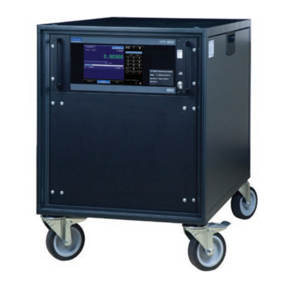
2. Short Overview 2. Short Overview The CPC8000-H hydraulic high pressure controller is a multi-range automatic pressure controller designed to test and calibrate a variety of pressure devices such as pressure gauges, pressure switches, sensors, transducers and transmitters. It can have up to two internal pressure reference transducers and an optional barometric reference for gauge or absolute emulation. -
Page 11: Components
2. Short overview Components 2.2.1 CPC8000-HC pneumatic pressure controller The CPC8000-HC is composed of: A CPC8000 pnuematic pressure controller ■ A 35 bar (508 psi) gauge pilot transducer ■ Optional internal barometric reference transducer ■ Touchscreen interface for local operation ■... -
Page 12: Front Panel
To see information about the configuration of your new CPC8000-H, touch the Info button under the settings menu and a window will appear listing the Mensor contact information, model number and the transducers that are installed. Press the back arrow to return to the Home screen. -
Page 13: Display
2. Short overview Display The display is made up of two sections. In the main screen, the left two thirds shows the operating screen displaying the active pressure reading, units, mode (absolute or gauge), setpoint, bar graph (if enabled), zero button (if enabled), tare button (if enabled), and up to two auxiliary displays that are user selectable. -
Page 14: Safety
WIKA/Mensor service engineer. Handle electronic precision measuring instruments with the required care (protect from humidity, impacts, strong magnetic fields, static electricity and extreme temperatures, do not insert any objects into the instrument or its openings). -
Page 15: Improper Use
3. Safety Improper Use WARNING! Injuries through improper use Improper use of the instrument can lead to hazardous situations and injuries. ▶ Refrain from unauthorized modifications to the instrument. ▶ Do not use the instrument within hazardous areas. ▶ Use only hydraulic media specified in user manual. (Consult factory for non-specified media) Any use beyond or different to the intended use is considered as improper use. -
Page 16: Personal Protective Equipment
3. Safety Personal Protective Equipment The personal protective equipment is designed to protect the skilled personnel from hazards that could impair their safety or health during work. When carrying out the various tasks on and with the instrument, the skilled personnel must wear personal protective equipment. - Page 17 CAUTION USE THE PROPER PRESSURE MEDIUM! Use only clean, dry air or nitrogen for the CPC8000-HC and only specified medium on the CPC8000-HM unless otherwise specified by Mensor. CAUTION As with most sensitive electronic equipment, switch the power switch off before connecting or disconnecting to a power source to prevent data loss.
-
Page 18: Transport, Packaging And Storage
4. Transport, Packaging and Storage 4. Transport, Packaging and Storage Transport Check the hydraulic high pressure controller CPC8000-H for any damage that may have been caused by transport. Obvious damage must be reported immediately. CAUTION! Damage through improper transport With improper transport, a high level of damage to property can occur. ▶... -
Page 19: Installation
5. Installation 5. Installation Personnel: Skilled electrical and mechanical personnel The following instructions must be followed in setting up the instrument for the first and any time after transporting to a different location WARNING! READ THESE INSTRUCTIONS BEFORE INSTALLATION! WARNING! Physical injuries and damage to property and the environment caused by hazardous media Upon contact with hazardous media (e.g. -
Page 20: Cpc8000-Hc
5. Installation 5.2.1.1 CPC8000-HC The CPC8000-HC module has 6 pressure ports: barometric reference, supply, exhaust, vent, reference, and measure/control port. • The barometric reference port uses a barb fitting with a 10-32 unf thread. This port is used to monitor atmospheric pressure when the optional barometric reference transducer is installed. -
Page 21: Communication Ports
WARNING! Never disconnect test ports while pressurized! Be sure the instrument is fully vented and the source pressure is turned off while disconnecting connections and hoses from the Measure/Control port. Failure to disassemble the test ports correctly could result in leaking liquids and gasses. -
Page 22: Measure/Control Test Port Prefilling
5.2.4 Measure/Control test port prefilling The Device Under Test must be filled with the hydraulic media to perform to the rated specifications. If there is not an designed user designed method to prefill the DUT, the following method may be used. 1. - Page 23 WIKA operating instructions hydraulic high pressure controller model CPC8000-H...
-
Page 24: Operation
6. Operation 6. Operation General Operation This section describes the procedures for operating the CPC8000-H from the front panel. Instructions for operating the device remotely from an external computer are covered in Section 8, Remote Operations. By following the procedures provided in these two sections and section 9.2, Recalibration, you can expect your CPC8000-H to deliver maximum accuracy and dependability for many years of useful service. -
Page 25: Initial Setup
Select the Settings application on the top right of the screen and navigate to the information application. The information tab will contain the Mensor contact, installed transducers, installed regulator along with instrument and software version information. Figure 6.2.1 Information Screen... -
Page 26: Language Selection
6. Operation 6.2.2 Language Selection Pressing the Settings button and navigating to the General tab, will display the options for Language, Secondary Display, Tertiary Display, Cal Function, Brightness, Volume, Barometer (optional), Load and Save. The language selections available are shown in the column on the right and the active language will be highlighted blue. Figure 6.2.2 Language Selection Application Selection and Parameter Inputs The data entry section on the right third of the screen (see figure 6.1.3 Display Screen Features) is the area where... -
Page 27: Range Hold
6. Operation Figure 6.4.1-B Main Screen w/Auxiliary Figure 6.4.1-C Main Screen Units 6.4.1.1 Range Hold The Range Hold button allows the user to select the active range transducer from a list of installed transducers. By clicking Range Hold, the user can select the active transducer from the primary and optional secondary transducer. The instrument must be fully vented in order to switch between ranges. -
Page 28: Numeric Keypad
6. Operation Figure 6.4.1.2-B Setpoint 6.4.1.3 Numeric Keypad The default entry method provides 10 digits for numeric entry, plus the decimal point and sign key (Figure 6.4.1.3). Each key that is pressed will display in the blue text box directly above the keypad. The sign key will allow the user to toggle between positive and negative values. -
Page 29: Percent Step
6. Operation Figure 6.4.1.4 Number Pad 6.4.1.4.1 Percent Step The Percent Step entry method allows the user to select setpoints based on a percentage of the primary transducer installed. Pressing the transducer range button at the top will open the Step Settings application (Figure 6.4.1.4.1-B). In this application, the user can select between 2 to 12 preset steps in percentages or pressure values, overrange percent, and minimum and maximum DUT limits. -
Page 30: Programs
6. Operation Figure 6.4.1.2.4 Digit Step 6.4.1.4.3 Programs The Programs entry method provides an automated way to interact with the CPC8000-H. Many settings or processes that can be entered manually can be programmed into the unit and saved and used in the Program portion of the keypad entry screen. Programs can be created, edited, deleted and saved in the Program application located under the Settings , then... -
Page 31: Favorites
6. Operation 6.4.1.5 Favorites The Favorites application provides access to up to 8 sequences. Unlike the Programs application, the Favorites does not have a scroll wheel to cycle through all programs available. This application is primarily for programs that are frequently used. The displayed programs can be set/saved in the Favorites application, which is accessed by selecting the Settings button then... -
Page 32: Bar Graph And Control Limits
6. Operation 6.4.1.7 Bar Graph and Control Limits The Bar Graph is always active on the main screen and it displays the real time pressure on the Measure/Control port. It is displayed in the form of a blue bar that spans left to right to provide a visual comparison between the actual pressure and the control limits. -
Page 33: Operating Modes
6. Operation 6.4.1.9 Operating Modes The CPC8000-H has three operating modes: Measure, Control, and Vent. After the system has been switched on and the bootup sequence has run, the instrument will automatically be placed in Measure mode. The operator can switch from one mode to another by using the mode selection keys located on the bottom row of the Main screen. -
Page 34: Vent Mode
6. Operation Figure 6.4.1.9.2-A Control Mode Figure 6.4.1.9.2-B Control Mode 6.4.1.9.3 Vent Mode The Vent mode is activated by pressing the Vent button on the bottom right of the screen. When selected, it will become highlighted blue (Figure 6.4.1.9.3). During Vent mode, the CPC8000-H will relieve all pneumatic and hydraulic pressure that is on the system. -
Page 35: General Settings
6. Operation 6.4.2 Settings The Settings application can be accessed by selecting the gears icon located on the top right of the Main screen. This application gives access to all general, sensor, remote, control, applications and information settings and menus. The settings application provides the user with many customizable options that can be easily accessed. -
Page 36: Auxiliary Displays
6. Operation 6.4.2.1.2 Auxiliary Displays The CPC8000-H homescreen has 2 available slots for additional auxiliary displays. These two displays can be chosen on the General settings application by selecting "Secondary Display" or "Tertiary Display". Each of these options can be configured to show the peak, rate, sensor 3 (pilot sensor), units, tare, or uncertainty. - Page 37 6. Operation • Zero Function When the zero option is chosen, it will become displayed on the upper left side of the main screen (Figure 6.4.2.1.3-A). The zero function allows the active transducer to perform a zero point calibration from the home screen. This operation will be permanently saved to the transducer memory if the instrument is in the native pressure units.
-
Page 38: Brightness
6. Operation 6.4.2.1.4 Brightness The Brightness settings can be adjusted by selecting the "Brightness" button and pressing a location on the green bar graph on the right side of the screen (Figure 6.4.2.1.4). This can be adjusted from 10% at the bottom point, up to 100% at the top. This adjustment will be implemented on all screens and can be saved to configurations. -
Page 39: Configurations Load/Save
6. Operation Figure 6.4.2.1.6 Barometer Units 6.4.2.1.7 Configurations Load/Save The Load and Save buttons will give access to the configuration files that are used to save or load different instrument settings. When the Load button is selected, a list of 8 different configurations will appear on the right side of the screen (Figure 6.4.2.1.7-A). These configurations can be chosen by pressing the configuration button and selecting the button when prompted to load the selected configuration (Figure 6.4.2.1.7-B). -
Page 40: Sensor Settings
6. Operation 6.4.2.2 Sensor Settings The Sensor settings can be accessed by entering the Settings application from the Main screen and choosing the Sensor tab on the bottom row. This application allows adjustments to the filtering, resolution, units, rate units, and user units 1 and 2. All of these adjustments are applied as changes to the instrument software, they are not permanently stored on the sensor. -
Page 41: User Units And Multiplier Settings
6. Operation Figure 6.4.2.2.3 Units 6.4.2.2.4 User Units and Multiplier Settings The User unit settings can be found in the Sensor settings application by pressing the "User Units" button (Figure 6.4.2.2.4-A). These units are used to setup the "base unit" and along with a multiplier used to define User Unit 1 and User Unit 2. For each of these units, the same process can be followed. -
Page 42: Maximum And Minimum Limits
6. Operation Figure 6.4.2.3 Control Settings 6.4.2.3.1 Maximum and Minimum Limits The Maximum and Minimum Limits can be found in the Control application. By default, the Control application will have the Maximum Limit selected when first accessed(Figure 6.4.2.3). The Maximum/Minimum Limit will display a keypad on the right side of the screen that will be limited by a range directly beneath the blue entry box. -
Page 43: Vent Limit
6. Operation Figure 6.4.2.3.2-B Stable Delay Figure 6.4.2.3.2-A Stable Limits Figure 6.4.2.3.2-C Graph Illustration 6.4.2.3.3 Vent Limit The Vent Limit can be found within the Control application by pressing "Vent Limit" (Figure 6.4.2.3.3). This is the pressure at which the controlled vent stops and the vent solenoid is opened, causing the pressure to vent through the vent port uncontrolled. The vent limit can be set within the values. -
Page 44: Tank Pump
6. Operation Figure 6.4.2.3.3 Vent Limit 6.4.2.3.4 Tank Pump The Tank Pump setting can be found in the Control application and modified by pressing "Tank Pump"(Figure 6.4.2.3.4). The Tank Pump is the number of cycles that the priming process will attempt before failure. This process occurs when the instrument is switched from Vent mode to Control mode. -
Page 45: Command Set
6. Operation Figure 6.4.2.4 Remote Settings 6.4.2.4.1 Command Set The Command Set button within the Remote application provides a place for the operator to choose which command set that will be used within remote communication software to control and query the CPC8000-H. When the Command Set button is selected, any of the listed command sets available will appear on the right side of the screen (Figure 6.4.2.4). -
Page 46: Ieee-488 Address
6. Operation 6.4.2.4.3 IEEE-488 Address The IEEE-488 Address button within the Remote application proivdes a place for the operator to set the IEEE-488 address(Figure 6.4.2.4.3). When this button is selected, a keypad will appear on the right side of the screen. The operator can input a value between 1 and 31 to change the address of the instrument. -
Page 47: Applications Settings
6. Operation Figure 6.4.2.4.5 Serial Settings 6.4.2.5 Applications Settings The Applications settings can be accessed by entering the Settings application from the Main screen and choosing the Applications tab on the bottom row. This application allows adjustments to the calibration settings, programs, favorites, troubleshooting and service settings. - Page 48 6. Operation Figure 6.4.2.5.1-A Programs Display The Edit tab(Figure 6.4.2.5.1-B), allows the user to edit existing programs or create steps in new ones. Pressing a command or data point will present the available commands or data entry type in the side bar. The Insert/Delete buttons allow insertion or deletion of commands and data entries.
-
Page 49: Favorites
6. Operation 6.4.2.5.2 Favorites The Favorites application is accessible on the Applications tab. When the Favorites button is pressed, the current list of favorites will be shown in a list (Figure 6.4.2.5.2). The selection bar on the right side of the screen will list all available programs saved to the CPC8000-H. -
Page 50: Remote Operation
Command Set Command Set button – Users’ can select which model remote protocol they would like to emulate for simulation and testing purposes. Selections may include the following or may be added per customers’ specifications: Mensor ■ Wika SCPI ■... -
Page 51: Serial
7. Remote Operation Serial Set the Serial communication parameters as shown in Section 6.4.2.4 Remote Settings. The serial communication port allows the CPC8000-H to communicate in RS-232 format with computers, terminals, PDAs, or similar hosts. These parameters should be set to match your host computer. Default settings are: 57600 baud, 8 data bits, 1 stop bit, no parity, and no echo. -
Page 52: Mensor Command Set
Mensor Command Set This Mensor command set is the default on the CPC8000-H. For queries (ending with a ?), the Data column represents the response of the CPC8000-H. All response strings begin with a space character or an “E” representing that there is an error in the error queue. -
Page 53: Mensor Commands And Queries
7. Remote Operation 7.6.4 Mensor Commands and Queries Table 7.6.4 lists all of the current Mensor commands and queries. Table 7.6.4 Command/Query Data Function/Response See Section 7.2 Remote Returns data per the current output format. Command Set Absolute? <sp>YES or NO<cr><lf>... - Page 54 AUXDISP2 (kept for backwards compatibility). Baro? <sp>+n.nnnnnE+nn<cr><lf> Returns reading from barometric transducer or “NO BAROMETER” if one isn’t installed. Baroid? <sp>Mensor,SN XXXXXX, Returns identification string for the barometer. VN.NN<cr><lf> Barocaldisable YES,NO Not used, kept for backwards compatibility. Barocaldisable? <sp>(YES or NO)<cr><lf>...
- Page 55 Height? <sp>+n.nnnnnE+nn<cr><lf> Gets the head pressure height in inches. HYDRSN? cccccccc Returns the hydraulic unit serial number <sp>MENSOR, CPC8000-H, Ssssss is the serial number, v.v.vv is the ssssss,v.v.vv<cr><lf> CPC8000-H software version. INSTRUMENT_ nnnnnn Returns the time the instrument has been TIME_ON? powered on, in minutes.
- Page 56 7. Remote Operation Keylock YES or NO Locks or unlocks the entire touch screen. Keylock? <sp>(YES or NO)<cr><lf> Returns Yes or No. Language CCCCCCC Set the active display language. Accepts the following: ENGL, ENGL US, ENGL CA, ENGL GB, GERM DE, GERM SZ, DEUT DE, DEUT SZ, FREN, FREN CA, FREN SZ, FREN CH, FRAN , FRAN CA, FRAN SZ, FRAN CH, SPAN MX, SPAN SP, SPAN LAT, SPAN...
- Page 57 7. Remote Operation Outform 1 to 7 Sets the output format (see Section 8.2) Outform? <sp>X<cr><lf> Returns the output format Overrange Set the overrange percentage Overrange? <sp>+n.nnnnnE+nn<cr><lf> Get the overrange percentage Peakmax? <sp>+n.nnnnnE+nn<cr><lf> Returns the maximum pressure since peakreset was sent. Peakmin? <sp>+n.nnnnnE+nn<cr><lf>...
- Page 58 7. Remote Operation RESET_INSTRU- Reset the "instrument control time on" counter MENT_CONTROL_ to 0. TIME_ON Resolution <n> Sets the number of significant digits. See decpt Resolution? <sp>n<cr><lf> Returns the number of significant digits. See decpt Rfilter Value in % Sets the % of the rate filter. Rfilter? <sp>+n.nnnnnE+nn<cr><lf>...
- Page 59 7. Remote Operation Setpoint% nnn.nnn Sets the control setpoint in %FS of primary transducer range Setpoint%? <sp>nnn.nnnnE+nn<cr><lf> Returns the current setpoint in % of primary transducer range. Alias for “Setpt%?” Setpt nnn.nnn Sets the control setpoint for the instrument. Value must be inside upper and lower limits Setpt? <sp>+n.nnnnnE+nn<cr><lf>...
- Page 60 Returns the tare value applied to all transduc- ers in current units. Termchar Set the termination character for the active command set (for example the Mensor command set will be different from the SCPI command set). Accepts the following: CRLF, CR, LF, EOI, NONE, DEFAULT Termchar? <sp>CCCC<cr><lf>...
-
Page 61: Wika Scpi Command Set
Returns the vent limit in current units. VENT_RATE Set the controlled vent rate VENT_RATE? <sp>+n.nnnnnE+nn<cr>><lf> Returns the controlled vent rate WID? <sp>MENSOR,WIKASN,X. Returns manufacturer, instrument’s Wika XX.XX<cr><lf> serial number, instrument software version number Window Value in current units Sets the exponential filter window for the... - Page 62 7. Remote Operation Table 7.7 Command or Query Response/Function MEASure [:PRESsure] [R]? Returns the pressure from range R. :TEMPerature[R]? Returns the temperature from range R. :RATE[R]? Returns the pressure rate/sec from range R. :BAROmetric? Returns the barometric pressure. :SLEW[R]? See MEASure:RATE? CALibration [:PRESsure][R] :MODE?
- Page 63 7. Remote Operation :ACTive <n> Sets the active transducer :ACTive? Returns the active transducer SYSTem :DATE <i,i,i> Not used, kept for backwards compatibility :DATE? Not used, does not cause an error, does not return a response. :TIME <i,i,i> Not used, kept for backwards compatibility :TIME? Not used, does not cause an error, does not return a response.
- Page 64 7. Remote Operation Index Unit mbar kp/cm² lbf/ft² cmH2O(4°C) inH2O(4°C) inH2O(20°C) inH2O(60°F) ftH2O(4°C) mmHg(0°C) cmHg(4°C) inHg(0°C) inHg(60°F) % of range user units 1 user units 2 OUTPut :STATe ON/OFF/1/0 ON or 1 = Control OFF or 0 = Measure. :STATe? Returns 0 for measure 1 for control.
- Page 65 7. Remote Operation :UPPer? Returns maximum control limit. :VENT <n> Pressure at which the vent solenoid opens for an uncon- trolled vent. :VENT? Returns the pressure at which the vent solenoid opens. :VRATE Sets the rate at which the controlled vent goes to atmosphere.
-
Page 66: Maintenance And Recalibration
The media should be replaced every 2 years to prevent damage to the internal seals. If you have questions not covered by this manual, call 1-800-984-4200 (USA only), or 1-512-396-4200 for assistance, or send an email to tech.support@mensor.com. WIKA operating instructions hydraulic high pressure controller, model CPC8000-H... -
Page 67: Beyond The Warranty
(typically 8 to 10 years). • All repairs associated with the chassis or internal modules should be performed by Mensor due to the complexity of performing these repairs. -
Page 68: Transducer Removal
8. Maintenance and Recalibration Always use the media that is labeled on the instrument, never mix media. 8.2.3 Transducer Removal All transducers within the CPC8000-H can be removed and replaced. The following instructions are to be used when removing or replacing any of these sensors. -
Page 69: Recalibration
Calibration Services by Mensor or WIKA Worldwide Mensor and WIKA worldwide have extensive experience and knowledge of Mensor products. Calibration of the transducers in these products can be performed at the addresses below or by competent internal or external labs using the procedures in this section. -
Page 70: Environment
8.3.3 Pressure Standards Mensor recommends the use of appropriately accurate primary pressure standards when calibrating this instrument. Such standards should be sufficient so that when the techniques of the ISO Guide of the Expression of Uncertainty in Measurement (GUM) are applied, the instrument meets its accuracy statements as required by ISO/IEC 17025:2017, or other applicable standards. -
Page 71: Calibration Data
8. Maintenance and Recalibration 8.3.6 Calibration Data The calibration data information for each transducer is stored under the "Info" tab in the 1 point, 2 point, or linearize calibration application(Figure 8.3.6 Calibration Data). The serial number (S/N), range, units, pressure type, accuracy, calibration date, zero offest (Zero), span offset (Span), calibration interval and transducer software version can be seen on this screen. -
Page 72: Point Calibration Application
8. Maintenance and Recalibration 8.3.8 2 Point Calibration Application The 2 point calibration application provides a place to adjust the transducer zero and span (sometimes referred to as offset and slope)(Figure 8.3.8 Two Point Calibration). Figure 8.3.8 Two Point Calibration Follow the steps below for a complete Two Point Calibration: Select a transducer to calibrate by pressing the corresponding transducer on the bottom of the screen. - Page 73 8. Maintenance and Recalibration transducer should be entered into the column labeled “Actual”. To enter readings, simply press the corresponding point in the “Reference” or “Actual” columns and a data entry keypad will appear on the side bar. Enter and accept the point using the key pad and check mark.
-
Page 74: Dismounting, Return And Disposal
9. Dismounting, Return and Disposal 9. Dismounting, Return and Disposal WARNING! Physical injuries and damage to property and the environment through residual media Residual media in the dismounted instrument can result in a risk to persons, the environment and equipment. ▶... -
Page 75: Return
9. Dismounting, Return and Disposal Return Strictly observe the following when shipping the instrument: All instruments delivered to Mensor must be free from any kind of hazardous substances (acids, bases, solutions, etc.) must therefore be cleaned before being returned. WARNING! Physical injuries and damage to property and the environment through residual media Residual media in the dismounted instrument can result in a risk to persons, the environment and equipment. -
Page 76: Specifications
These specifications are obtained in accordance with the ISO Guide to the Expression of Uncertainty in Measurement (GUM). The calibration program at Mensor is accredited by the American Association of Laboratory Accreditation (A2LA) as complying with both the ISO/IEC 17025:2017 and the ANSI/NCSL Z540-1-1994 standards. - Page 77 0 ... 95 % r. h. (non-condensing) Compensated temperature range 15 ... 45 °C (59 … 113 °F) Mounting position Horizontal Comunication Interface IEEE-488.2, Ethernet, USB, RS-232 Command sets Mensor, WIKA SCPI Response time < 100 ms WIKA operating instructions hydraulic high pressure controller model CPC8000-H...
-
Page 78: Approvals And Certificates
10. Specifications 10.2 Approvals and Certificates 10.3 Approvals and certificates EC declaration of conformity EMC directive EN 61326-1 emission (group 1, class A) and interference immunity (industrial application) Low voltage directive EN 61010-1 RoHS directive 2011/65/EU, article 4 Certificate Calibration Standard: A2LA calibration certificate (standard on factory) Optional: DKD/DAkkS calibration certificate 8) Warning! This is class A equipment for emissions and is intended for use in industrial environments. - Page 79 10. Specifications WIKA operating instructions hydraulic high pressure controller model CPC8000-H...
-
Page 80: Cpc8000-Hm Hydraulic Module
10. Specifications 10.4.2 CPC8000-HM hydraulic module WIKA operating instructions hydraulic high pressure controller, model CPC8000-H... -
Page 81: Cpc8000-Hc Pneumatic Controller (Inches)
10.4.3 CPC8000-HC pneumatic controller (inches) WIKA operating instructions hydraulic high pressure controller model CPC8000-H... -
Page 82: Accessories
11. Accessories 11. Accessories Barometric reference sensor (for pressure emulation) ■ Barometric reference calibration sled ■ CPR8000 reference pressure sensor calibration sled with power supply ■ CPR8050/8850 reference pressure sensor calibration sled with power supply ■ Operating fluid: Sebacate or Shell Tellus. ■... -
Page 83: Cpr8000 Reference Calibration Sled
11. Accessories 11.3.1 CPR8000 Reference Calibration Sled The CPR8000 Reference Calibration Sled Kit is available to provide a way to calibrate the reference pressure transducer remotely. Calibration of the CPR8000 can be performed remotely using the Cal sled, a PC and the software provided. 11.3.2 CPR8050 and CPR8850 reference pressure calibration sled The CPR8050 and CPR8850 have a female 1/4-28UNF port that requires a cone and thread male fitting for pressure connection. - Page 84 12. Appendix 12. Appendix 12.1 Measurement Units Table 12.1 Measurement Units (unitno) Code Description Output Format pounds per square inch inches of mercury @ 0°C in Hg 0°C inches of mercury @ 60°F in Hg 60°F inches of water @ 4°C in H2O 4°C inches of water @ 20°C in H2O 20°C...
- Page 85 12. Appendix User Units 1 User defined User Units 2 User defined 12.2 Conversion Factors, PSI The values listed in the column “To convert from PSI” are the values imbedded in the instrument program. The values listed under “To convert to PSI” are internally calculated approximations based on the imbedded values. Table 12.2 Conversion Factors, PSI Code Pressure Unit...
- Page 86 12. Appendix cmH2O 20°C 70.4336 0.01419777 MH2O 20°C 0.704336 1.419777 WIKA operating instructions hydraulic high pressure controller, model CPC8000-H...
- Page 87 12. Appendix WIKA operating instructions hydraulic high pressure controller model CPC8000-H...
- Page 88 WIKA subsidiaries worldwide can be found online at www.wika.com. Mensor Corporation WIKA Alexander Wiegand SE & Co. KG 201 Barnes Drive Alexander-Wiegand-Straße 30 San Marcos, TX 78666 • USA 63911 Klingenberg • Germany Tel. (+1) 512 3964200-15 Tel. +49 9372 132-0...
Need help?
Do you have a question about the WIKA CPC8000-H and is the answer not in the manual?
Questions and answers