
Related Manuals for mensor 9414


Summary of Contents for mensor 9414
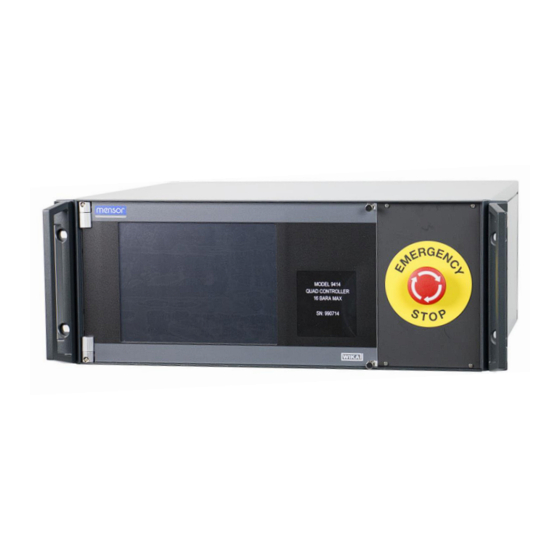
- Page 1 Operation Manual - PN 0017964001 Multi-Channel Pressure Controller Mensor Model 9414 Mensor Model 9414 Multi-Channel Pressure Controller 0017964001A 9/13/12 Mensor LP, 201 Barnes Drive, San Marcos, TX, USA...
- Page 3 Control of up to 8 solenoids valves (12vdc at a maximum of 1 amp) can be done with the 9414 controller and is provided to the user through the same 25 pin D-sub connector containing the RS-485 signals.
- Page 4 P2 and the other is for channels P3 and P4. The quad pressure control output ports are located on the rear of the 9414 and are labeled P1, P2, P3 and P4 Control. Pressure input ports are also in the upper left quarter of the rear panel and are labeled P1, P2, P3 and P4 Measure.
- Page 5 Space is provided in this area to display the channel setpoint, the actual pressure reading and the mode of operation for each of the four channels. If the 9414 is populated with only two channels, the bottom two areas will be blank. In the lower right corner is a status window.
- Page 6 SHUTOFF button has been pressed, this should be rotated clockwise to disengage. The normally open vent valves will automatically close. The system will interrogate the 9414 for installed control channels. This will typically be either two or four. The system will than check for remote transducers. The system can have one to four attached transducers.
- Page 7 1 stop bit and no parity. These RS485 communications along with the 8 solenoid drive signals can be found on the 25 pin D-Sub located on the rear of the 9414. The 9414 handles all communication with the transducer(s) inside the module as well as provide the 12 volt DC power to the external transducer(s) and solenoid valves when present.
- Page 8 Controller. Where applicable, this command set is maintained in the 9414 System Controller/ Quad Pressure Controller. Model 9411 commands that have limited use in the 9414 based system are highlighted in gray. The user should determine if the commands highlighted in gray are necessary based on initial configuration and the overall system configuration.
- Page 9 2 is second. or 0 if not transducer attached. xlo? Returns pressure reading Returns two sets of 8 from both low pressure character values with transducers (x3 and x4) 3 fractional digits Mensor Model 9414 Multi-Channel Pressure Controller 0017964001A 9/13/12...
- Page 10 Energizes solenoid 12 s12off De-energizes solenoid 12 s14on Energizes solenoid 14 s14off De-energizes solenoid 14 s16on Energizes solenoid 16 s16off De-energizes solenoid 16 ventall Turns off regulators and places channels in vent Mensor Model 9414 Multi-Channel Pressure Controller 0017964001A 9/13/12...
- Page 11 Places controller in measure mode. Commands set of the pressure controller portion of the 9414 SetP1= Enters the control pressure Example: setpoint for P1 in the current SetP1= 450 units of measurement.
- Page 12 Returns the status of P2 ReadyP2 pressure channel. Returns YES if P2 pressure is within pressure window setting or NO if not within window. See SETWINDOW command. ReadyP3? Returns the status of P3 ReadyP3? Mensor Model 9414 Multi-Channel Pressure Controller 0017964001A 9/13/12...
- Page 13 (STBY). ModeP2= Sets P2 channel to Measure ModeP2= Vent (MEAS), Control (CTRL), Vent (VENT), or Standby (STBY). ModeP3= Sets P3 channel to Measure ModeP3=STBY (MEAS), Control (CTRL), Vent (VENT), or Standby (STBY). Mensor Model 9414 Multi-Channel Pressure Controller 0017964001A 9/13/12...
- Page 14 The sequence controls the order that operations are executed. See SEQTYPE command below SeqP3 Starts pressure 3 sequence SeqP3 of events. The sequence controls the order that operations are executed. See SEQTYPE command Mensor Model 9414 Multi-Channel Pressure Controller 0017964001A 9/13/12...
- Page 15 100.104 transducer 3, and remote transducer 4. Ver? Returns the version of the Returns: internal software Version: 1.01 Returns the unit serial Returns: number SN: 990248 Lockpanel Disables the front panel Lockpanel Mensor Model 9414 Multi-Channel Pressure Controller 0017964001A 9/13/12...
- Page 16 P2, P3 and P4 valves. RouteP2 Connects pressure P2 to RouteP2 Device Under Test (DUT) if Pressure Select Manifold is present in remote transducer module. Closes vent valve along with P1, P3 Mensor Model 9414 Multi-Channel Pressure Controller 0017964001A 9/13/12...
- Page 17 1.3000, 2.0000,- 0.7000,-1.1000, - 2.0000 mult: 1.000 Mult= Increases or decreases the MULT=1.25 overall gain of the pressure regulators. Default value is 1.0. Values less than 1 decrease the sensitivity of Mensor Model 9414 Multi-Channel Pressure Controller 0017964001A 9/13/12...
- Page 18 Vn2 must be a negative value that is smaller than vn3 and greater than vn1. Vn3= Increase or decrease the Vn3=-2.2 overall sensitivity of the course exhaust control valve. See ‘gains?’ Mensor Model 9414 Multi-Channel Pressure Controller 0017964001A 9/13/12...
- Page 19 Go to next pressure….(step 7A ) Normal Shutdown Sequence: The normal shutdown mode should place each channel of the 9414 in the measure mode. The VAC enable and the AIR enable valves Mensor Model 9414 Multi-Channel Pressure Controller 0017964001A 9/13/12...
- Page 20 Mensor Series 6100 or 6180 Digital Pressure Transducers mounted in the remote transducer module. The range on these transducers is application specific. The Mensor Model 9414 Quad Controller also incorporates four 300 psi Absolute (~2068 kPa) or 233 psi (~16 bar) Series 6100 or Series 6180 transducers internally.
- Page 21 The transducers in the 9414 are not intended as the primary pressure standard in the system. They are intended to operate as feedback devices for the pressure regulators. If calibration of these devices is desired, they can be calibrated in the unit or externally.
- Page 22 0 (control channel P1). This value must be saved with the ‘save0=’ command to be retained through power down cycles. Sc1? Sc1= Sc2? Sc2= Sc3? Sc3= Id0? Id1? Id2? Id3? Save0= Save1= Mensor Model 9414 Multi-Channel Pressure Controller 0017964001A 9/13/12...
- Page 23 Make sure moving mechanical parts are not hindered with dust, dirt and are properly lubricated. This is especially true of the cooling fan in the rear of the unit. The calibration of the Mensor Series 6100/ 6180 Digital Pressure Transducers should be periodically checked.
- Page 24 +Rx (xdcr pin9) Gnd (xdcr pin 5) +12 v (xdcr pin 6) 9 pin signals (labeled Air Supply) Function Function 12 vdc Drive Common 12 vdc Drive Common 12 vdc Drive Common Mensor Model 9414 Multi-Channel Pressure Controller 0017964001A 9/13/12...
- Page 25 Appendix: Mensor CPT6180 Manual Mensor Model 9414 Multi-Channel Pressure Controller 0017964001A 9/13/12...
- Page 26 Mensor Corporation 201 Barnes Drive San Marcos, Texas 78666-5994 Phone: 512.396.4200 Fax: 512.396.1820 Web site: www.mensor.com E-mail: sales@mensor.com Mensor Model 9414 Multi-Channel Pressure Controller 0017964001A 9/13/12...
Need help?
Do you have a question about the 9414 and is the answer not in the manual?
Questions and answers