Table of Contents
Advertisement
Quick Links
PREVIOUS REFERENCE NO. IM-P470-09
4701036/3
IM-P240-02-EN-ISS1
CTLS
DP27T and DP27TE
Pilot Operated Pressure/Temperature
Control Valves
Installation and Maintenance Instructions
1. Safety information
2. General product
information
3. Installation
4. Commissioning
5. Maintenance
6. Spare parts
DP27T
7. Fault finding
DP27TE
© Copyright 2018
IM-P240-02-EN-ISS1 CTLS
1
Printed in GB
Advertisement
Table of Contents

Related Manuals for Spirax Sarco DP27T


Summary of Contents for Spirax Sarco DP27T
- Page 1 PREVIOUS REFERENCE NO. IM-P470-09 4701036/3 IM-P240-02-EN-ISS1 CTLS DP27T and DP27TE Pilot Operated Pressure/Temperature Control Valves Installation and Maintenance Instructions 1. Safety information 2. General product information 3. Installation 4. Commissioning 5. Maintenance 6. Spare parts DP27T 7. Fault finding DP27TE ©...
- Page 2 IM-P240-02-EN-ISS1 CTLS...
-
Page 3: Safety Information
Determine the correct installation situation and direction of fluid flow. iv) Spirax Sarco products are not intended to withstand external stresses that may be induced by any system to which they are fitted. It is the responsibility of the installer to consider these stresses and take adequate precautions to minimise them. -
Page 4: Protective Clothing
Allow time for temperature to normalise after isolation to avoid danger of burns. 1.9 Tools and consumables Before starting work ensure that you have suitable tools and/or consumables available. Use only genuine Spirax Sarco replacement parts. 1.10 Protective clothing Consider whether you and/or others in the vicinity require any protective clothing to protect against the hazards of, for example, chemicals, high/low temperature, radiation, noise, falling objects, and dangers to eyes and face. -
Page 5: Residual Hazards
1.16 Returning products Customers and stockists are reminded that under EC Health, Safety and Environment Law, when returning products to Spirax Sarco they must provide information on any hazards and the precautions to be taken due to contamination residues or mechanical damage which may present a health, safety or environmental risk. -
Page 6: General Product Information
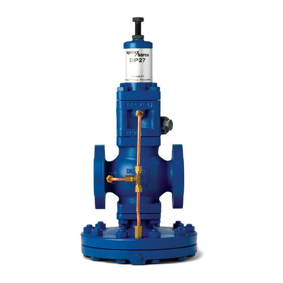
2. General product information 2.1 General description The DP27T and DP27TE are combined pressure/temperature control valves for use on steam applications. They are designed to be used in conjunction with a 2 m length of capillary which is available separately (other lengths available on request). They combine a temperature and pressure pilot valve in one unit. -
Page 7: Temperature Ranges
DP27TE Temperature ranges DP27T Range A 16 °C to 49 °C Range B 38 °C to 71 °C Range C 49 °C to 82 °C Range D 71 °C to 104 °C Range E 93 °C to 127 °C IM-P240-02-EN-ISS1 CTLS... -
Page 8: Pressure / Temperature Limits
232 °C @ 21 bar g Maximum operating temperature DP27TE 190 °C @ 10 bar g 0 °C Minimum operating temperature Note: For lower operating temperatures consult Spirax Sarco. DP27T 17 bar Maximum differential pressure DP27TE 17 bar Designed for a maximum cold hydraulic test pressure of:... -
Page 9: Installation
Referring to these Installation and Maintenance Instructions, name-plate and Technical Information Sheet, check that the product is suitable for the intended installation. The installation instructions are dealt with under two headings, 'The valve' and 'The temperature control system'. DP27TE Control head securing screws Fig. 1 DP27T IM-P240-02-EN-ISS1 CTLS... - Page 10 DP27TE The DP27TE pressure/temperature control is supplied as for the DP27T but a solenoid operated valve is fitted in the pipe between the pilot valve and the main diaphragm chamber, thus in series with the normal pilot valve.
- Page 11 DP27TE Control head securing screws Fig. 2 DP27T IM-P240-02-EN-ISS1 CTLS...
- Page 12 3.2 The valve General arrangement Figure 2 shows the recommended installation layout to ensure satisfactory operation of the DP27T pressure/temperature control. It should always be fitted in a horizontal pipeline with the main diaphragm chamber below the line. Pressure sensing pipe (see Section 3.8)
- Page 13 It should be arranged with a positive fall so that any condensate can drain away from the DP27T. Where the size of the reduced pressure main makes it difficult to maintain a fall when entering the top of the main, the pressure control pipe may be connected in the side of the main.
-
Page 14: Safety Valve
3.10 Bypass If it is essential to maintain a constant supply of steam and the reducing valve station does not include duplication or stand-by equipment, it may be necessary to install a bypass to ensure continuation of supply when the reducing valve is being serviced (see Figure 2). The bypass valve will normally be the same size as the reducing valve. - Page 15 ¾" BSP taper NPT available 3.14 Sensor bulb The type DP27T control is fitted with a plain bulb as in Figure 4, but as an optional extra this bulb is supplied with an adaptor shown in Figure 5, consisting of a union nipple (U), 'O' ring (V) and gland nut (W).
- Page 16 3.20 Wall mounting sensor Fig. 8 Where the type DP27T control is to be used to control from room temperature the plain bulb Figure 4 is used and a bracket and protective shield is provided Figure...
- Page 17 4. Commissioning Warning Direct injection systems This product contains a rust inhibitor to protect it against corrosion during storage. To avoid any possible contamination of your product, after first blowing down the approach pipework, we recommend that the valve is blown through thoroughly in order to remove any trace of the inhibitor.
- Page 18 4.2 To set the temperature 1. Check that the temperature scale can be easily seen. If it is fitted in a confined space facing a wall for example the control head may be repositioned to enable the scale to be more easily read as follows:- Undo the three screws.
-
Page 19: Routine Maintenance
5. Maintenance Note: Before actioning any maintenance programme observe the 'Safety information' in Section 1. Warning: The body gasket contains a thin stainless steel support ring which may cause physical injury if not handled and disposed of correctly. 5.1 Routine maintenance It is recommended that the valve is dismantled once every twelve to eighteen months for a complete overhaul and ideally this should be carried out with the valve removed from the line. - Page 20 5.2 How to renew the pilot filter element: 1. Isolate the reducing valve and zero the pressure. 2. Unscrew the filter cap and carefully withdraw the filter element. 3. Replace the element and tighten the filter cap to 90 - 100 N m. Note: The gasket is re-usable.
- Page 21 5.4 How to renew the pressure control pilot valve assembly: Isolate the valve and zero the pressure. Remove sensor bulb and allow it to cool down otherwise the control system may be strained. Follow Steps 1 to 5 then proceed as follows: 9.
- Page 22 13. Refit the pipework and temperature control pilot assembly, then retighten the unions to ensure a steam tight seal. 14. Refit the temperature control head. Complete assembly by following Steps 1 to 5 in reverse order. Bring the valve back into commission by following as many Steps as necessary in Section 4. The following handling precautions should be observed.
- Page 23 5.5 How to clean the strainer screen: Isolate the valve and zero the pressure. Remove the sensor bulb and allow it to cool down, otherwise the control system may be strained. Follow Steps 1 to 5 then proceed as follows: 15.
- Page 24 21. Fit a new gasket. 22. Replace the screen. 23. Assemble the pilot valve housings complete with the spring housing assembly and tighten the nuts to the recommended torques shown in Table 1, page 18. 24. Refit the pipework and retighten the unions to ensure a tight seal. 25.
- Page 25 5.6 How to renew pilot valve diaphragms: Isolate the reducing valve and zero the pressure. Remove sensor bulb and allow it to cool down, otherwise the control system may be strained. Follow Steps 1 to 5 then proceed as follows: 26.
- Page 26 5.7 How to renew or clean main diaphragms: Isolate the valve and zero the pressure. Remove the sensor bulb and allow it to cool, otherwise the control system may be strained. 30. Undo the long union nut and pull away. 31.
- Page 27 5.8 How to service or renew the main valve and seat: Isolate the valve and zero the pressure. Remove the sensor bulb and allow it to cool down, otherwise the control system may be strained. Follow Steps 1 to 5 then proceed as follows: 38.
- Page 28 42. Remove the main valve spring and main valve head. 43. Remove the main valve seat (see Table 2). Examine the faces of the main valve head and seat. If they are only slightly worn both the main valve head and main seat may be lapped on a flat plate using a fine grinding paste.
- Page 29 45. Undo the long nut and pull away. 46. Undo the M12 nuts and bolts. 47. Drop away the lower diaphragm chamber, the two diaphragms, diaphragm plate and pushrod assembly. 48. Refit the pushrod assembly. 49. Refit the main valve head making sure the valve locates on the seat.
- Page 30 52. Thoroughly clean the upper and lower diaphragm chamber making sure that the contact faces are clean. 53. Replace the diaphragm plate and pushrod assembly and loosely fit the lower diaphragm chamber on the two bolts either side of the union connection to locate the spigot in the recess.
- Page 31 58. Refit the main valve head. 59. Replace the main valve return spring. 60. Fit new gasket. 61. Replace the screen. 62. Assemble the pilot valve housings complete with the spring housing assembly and tighten the nuts to the recommended torques shown in Table 1. 63.
- Page 32 5.9 How to renew the temperature control pilot valve assembly: Isolate the valve and zero the pressure. Remove the sensor bulb and allow it to cool down,otherwise the control system may be strained. 65. Undo the three screws and remove the temperature control head.
- Page 33 69. Unscrew and remove the pilot valve seat (20 mm A/F). 70. Screw the new pilot valve seat into the housing. 71. Assemble the pilot valve housing and tighten the nuts to 40 N m. 72. Refit the pipework and retighten the unions to ensure a steam tight seal.
- Page 34 5.10 How to renew the temperature control system: Isolate the valve and zero the pressure. Withdraw the sensor bulb from the plant and allow it to cool. 74. Undo the three screws and lift off the control head. 75. Fix the control head of replacement temperature control system in position.
- Page 35 5.11 How to service or renew the solenoid valve (DP27TE): Depressurize the valve and turn off the electrical power supply. 82. Remove the retaining clip and slip the entire solenoid enclosure off the solenoid base sub-assembly of the plug nut/core tube of the sub-assembly. 83.
-
Page 36: Spare Parts
6. Spare parts The spare parts available are shown in heavy outline. Parts drawn in broken line are not available as spares. Please note: A Table is shown on page 32 indicating interchangeability of spares. Available spares Maintenance kit A stand-by set of spares for general maintenance purposes and covers all spares marked * Main diaphragm * (2 off) Pilot diaphragms *... - Page 37 Always order spares by using the description given in the column headed 'Available spares' and state the size and type of the pressure/temperature control valve. E xample: 1 - Main valve assembly for a Spirax Sarco DN15 Type DP27T pilot operated pressure/temperature control valve. note below Coil Note: Items E and F are shown 180°...
- Page 38 Interchangeability of spares The following table shows how in certain sizes some parts are interchangeable. For example in the line headed 'Main diaphragm' the diaphragm used in the screwed valves ½", ¾" is common to these sizes by the letter 'a', the letter 'c' indicates that the one diaphragm is common to the DN32 and DN40 valve.
- Page 39 Screwed Flanged ½" ½" ¾" 1" DN15 DN15 DN20 DN25 DN32 DN40 DN50 Control head 'O' ring for sensor bulb adaptor Control pipe assembly Balance pipe † assembly Gasket set † Pilot valve block gasket Set of spring housing securing †...
-
Page 40: Fault Finding
7. Fault finding The DP27T pressure/temperature control system provides a combined unit for pressure reduction and temperature control. It is important to remember that when approaching the set temperature, the temperature control pilot valve will override and lower the downstream pressure. -
Page 41: Temperature Control System
Temperature control system 7.6 Temperature in plant too high. A rise in temperature above the normal control setting could be caused either by the valve failing to shut-off or a break down in the control system. Check as follows:- 7.7 With the plant up to temperature and steam on to the valve remove the sensor bulb and allow it to cool. - Page 42 Temperature in plant too low 7.15 If the temperature in the plant is below the normal control setting this could be caused by one of the following: 7.16 Lack of steam supply. Check that steam is turned on and that the strainers are clean. 7.17 Pipe assembly blocked.
- Page 43 IM-P240-02-EN-ISS1 CTLS...
- Page 44 IM-P240-02-EN-ISS1 CTLS...
Need help?
Do you have a question about the DP27T and is the answer not in the manual?
Questions and answers