Advertisement
Available languages
Available languages
Quick Links
Assembly and operating instructions
DULCOTEST
sensor ICT 5 and ICT 5-IMA
®
Sensor for electrical conductivity
EN/DE
A2632
Please carefully read these operating instructions before use. · Do not discard.
The operator shall be liable for any damage caused by installation or operating errors.
The latest version of the operating instructions are available on our homepage.
982358
BA DT 157 10/18 DE/EN
Advertisement
Chapters

Related Manuals for ProMinent DULCOTEST


Summary of Contents for ProMinent DULCOTEST
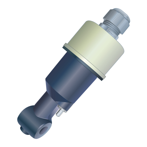
- Page 1 Assembly and operating instructions DULCOTEST sensor ICT 5 and ICT 5-IMA ® Sensor for electrical conductivity EN/DE A2632 Please carefully read these operating instructions before use. · Do not discard. The operator shall be liable for any damage caused by installation or operating errors.
- Page 2 Overall Table of Contents Overall Table of Con‐ Permitted process pressure..32 tents Dimensions........ 33 DULCOTEST ® Sensor ICT 5 und DULCOTEST sensor ICT 5 and ICT ® ICT 5-IMA Sensor für elektrolytische 5-IMA Sensor for electrical conduc‐ Leitfähigkeit........36 tivity.............
- Page 3 Overall Table of Contents Abmessungen......65...
-
Page 4: Tivity
Assembly and operating instructions DULCOTEST sensor ICT 5 and ICT 5-IMA ® Sensor for electrical conductivity A2632 Please carefully read these operating instructions before use. · Do not discard. The operator shall be liable for any damage caused by installation or operating errors. - Page 5 Supplemental directives General non-discriminatory approach In order to make it easier to read, this docu‐ ment uses the male form in grammatical struc‐ tures but with an implied neutral sense. It is aimed equally at both men and women. We kindly ask female readers for their under‐...
- Page 6 Supplemental directives Symbol Description ‘Display /GUI’ Screen elements (e.g. buttons, assignment of function keys). Presentation of software elements and/or texts. CODE...
-
Page 7: Table Of Contents
Table of contents Table of contents Introduction..........................8 Measuring principle......................8 Construction and function of the sensor................. 9 Nameplate........................12 Scope of delivery......................12 Safety and responsibility....................... 13 Labelling of Warning Information.................. 13 User qualification......................15 General safety information................... 16 Intended use......................... -
Page 8: Introduction
You can also use both types of sensor in conta‐ tion on the technical data and functions of the minated water or in aggressive media, which is chemically inert to PVC/EPDM and/or PP/ DULCOTEST sensor for inductive conduc‐ ® EPDM (depending on the design of the sensor). -
Page 9: Construction And Function Of The Sensor
Introduction Construction and function of the sensor The inductive transducer of the two types of sensor ICT 5 and ICT 5-IMA consists of a hermetically sealed polypropylene (PP) body. A transmission coil and a receiver coil are incorporated in the transducer. - Page 10 Introduction Sensor type ICT 5 The sensor type ICT5 is connected to a standard DN40 T-piece (on site) using a threaded socket and a union nut for operation in the flow. A2641 Fig. 2: Sensor type ICT 5 Threaded socket, G 1 1/2” (PVC or PP) Union nut (PVC or PP)
- Page 11 Introduction Sensor type ICT5-IMA The sensor type ICT5-IMA is immersed by the fully assembled immersion tube (1 m) in the storage tank and channel. A2642 Fig. 3: Sensor type ICT 5-IMA Fixed cable, 10 m Threaded connector M16, degree of protec‐ tion, IP68 (up to 0.2 m)
-
Page 12: Nameplate
Introduction Nameplate The cell constant K is needed for calibration on the transmitter/controller. A2637 Fig. 4: ICT5 nameplate A2638 Fig. 5: ICT5-IMA nameplate Scope of delivery Scope of delivery of sensor type ICT 5: Sensor type ICT 5, order number 1095248 Straight solvent union PVC for adaptation of the sensor to a standard T-piece DN40, PVC (T-piece not included in the scope of... -
Page 13: Safety And Responsibility
Safety and responsibility Safety and responsibility Labelling of Warning Infor‐ mation WARNING! Introduction Nature and source of the danger These operating instructions provide informa‐ Possible consequence: Fatal or very tion on the technical data and functions of the serious injuries. product. - Page 14 Safety and responsibility NOTICE! Nature and source of the danger Damage to the product or its surround‐ ings. Measure to be taken to avoid this danger. – Denotes a possibly damaging sit‐ uation. If the situation is disre‐ garded, the product or an object in its vicinity could be damaged.
-
Page 15: User Qualification
Safety and responsibility User qualification WARNING! Danger of injury with inadequately qualified personnel The operator of the system / equipment is responsible for ensuring that the qualifications are fulfilled. If inadequately qualified personnel work on the unit or loiter in the hazard zone of the unit, this could result in dangers that could cause serious injuries and material damage. -
Page 16: General Safety Information
Safety and responsibility Training Definition Electrical technician An electrical technician is able to complete work on electrical systems and recognise and avoid possible dangers independently based on his technical training and experience as well as knowledge of pertinent standards and regulations. An electrical technician must be able to per‐ form the tasks assigned to him independently with the assistance of drawing documentation, parts lists, terminal and circuit diagrams. -
Page 17: Intended Use
Safety and responsibility Intended use Only use the sensor to measure and regu‐ late electrolytic conductivity in aqueous media, which are used in the applications described in these operating instructions. All other uses or modifications are pro‐ hibited. The sensor is not a safety component in the sense of DIN EN ISO 13849-1:2008-12. -
Page 18: How To Store And Transport The Sensor
How to store and transport the sensor How to store and transport the sensor Original packaging User qualification: instructed user, see Ä Chapter 2.2 ‘User qualification’ on page 15 Damage to the product. Only transport, ship and store the sensor in its original packaging. -
Page 19: Assembly And Installation
Assembly and installation Assembly and installation User qualification, mechanical installation: Make sure that the medium flows correctly Ä Chapter through and around the sensor. trained and qualified personnel 2.2 ‘User qualification’ on page 15 Maintain a minimum distance of 20 mm from User qualification, electrical installation: the sensor to the tube wall when installing in Ä... -
Page 20: Installation Of Sensor Type Ict 5
Assembly and installation Installation of sensor type ICT 5 Fitting position You can operate the sensor at any angle (0 ... 360°). The sensor is installed in a DN40 standard T- piece, as shown in Fig. 6 with regard to its flow and the minimum distances from the walls. A2618 Fig. - Page 21 Assembly and installation Hydraulic installation situation Please note the hydraulic fitting position indicated in Fig. 7. It is essential that the following are avoided: Formation of gas bubbles The device running dry Stalling Turbulence A2619 Fig. 7: Hydraulic fitting position / tick = OK, cross = not OK...
- Page 22 Assembly and installation Bonding the straight solvent union into a T-piece Installing the sensor type ICT5 into PVC pipework. You can install the sensor into a PVC section using the PVC straight solvent union supplied Colour Material Beige Grey Use suitable adhesive, resistant to the media, for the materials to be bonded. A2639 Fig.
-
Page 23: Installation Of Sensor Type Ict 5-Ima
Assembly and installation Align the straight solvent union so that the sample medium flows through the sensor eye (5). Align the guide lip (1) of the adhesive connector towards the T-piece in the flow direction. Installing the sensor type ICT5 into polypropylene (PP) pipework You can install the sensor directly into an optionally available PP T-piece (order number 1096349, not included in the scope of delivery). -
Page 24: Electrical Installation
The descriptions of the terminals refer to the ProMinent measuring and control unit, type DCCa. The information about the colours relates to the leads of the sensor’s fixed data line. Connect the data line to the terminals of your ProMinent measuring and control unit, type DCCa. In doing so, refer to the relevant operating instructions Connect the data line to the terminals of your measuring/control unit. - Page 25 Assembly and installation Tab. 3: General assignment for further measuring/control units Function Sensor ICT5 lead colours [bn] , brown Transmission coil, signal [wh] , white Transmission coil, signal, earth [pk] , pink Receiver coil, signal Receiver coil, signal, earth Cable shield for X2.1, transparent Earth Complete cable shield, black [gn] green...
-
Page 26: Maintenance
Maintenance Maintenance Check the complete measuring chain (sensor, connecting line and transmitter/ WARNING! controller) should there be deviations of the measured values with an unknown Danger from hazardous substances! cause. Possible consequence: Fatal or very serious injuries. Please ensure when handling haz‐ ardous substances that you have read the latest safety data sheets provided by the manufacture of the hazardous... -
Page 27: Rectifying Faults And Malfunctions
Rectifying faults and malfunctions Rectifying faults and malfunctions Problem Possible cause Measure No display of measured value No power supply Check power supply, check or signal output terminals Display of measured value is Sensor not immersed in the Top up storage tank 000 or signal output is 0% (e.g. -
Page 28: Disposal Of Used Parts
To do so, remove all traces of haz‐ ardous substances. Refer to the Material Safety Data Sheet for your feed chemical. A current Declaration of Decontamination is available to download on the ProMinent web‐ In accordance with the European Directive site. 2012/19/EU on waste electrical and electronic equipment, this device features the symbol showing a waste bin with a line through it. -
Page 29: Accessories
Accessories Accessories Description Part number Straight solvent union (PVC) + O-ring, for installation of sensor type ICT5 into a PVC 1096348 T-piece DN40 Union nut G 1 1/2”, PVC 1096351 T-piece, PP, DN40 with integral sensor adapter* 1096349 Union nut G 1 1/2”, PP 1096353 * Features an anti-turn locking device;... -
Page 30: Technical Data
Technical data Technical data General data Parameter ICT 5 ICT 5-IMA Design For operation in the flow For immersion Measuring principle inductive Measuring range 0 ... 2000 mS/cm Precision within the measuring range 0 ... 1 mS/cm ≤ 1% 0 ... 10 mS/cm ≤... -
Page 31: Certification/Test Marks
Technical data Parameter ICT 5 ICT 5-IMA at -10 ... +80 °C minimum -0.1 bar minimum -0.1 bar Sensor material, wetted Sensor body Protective sleeve, temperature Stainless steel 1.4571 sensor Seal EPDM Electrical connection Fixed cable, 10 m, PUR, lead Threaded cable connector M16, PBT/PA Length of immersion fitting... -
Page 32: Permitted Process Pressure
Technical data Permitted process pressure Temperature, pressure and the sample medium have an impact on the service life of the sensor. 60 70 80 A2624 Fig. 9: Permitted process pressure type ICT 5 fitted in PP pipework Pressure in bar. Temperature in °C. -
Page 33: Dimensions
Dimensions Dimensions III. Ø44,5 Ø40 120 ± 10 A2620 Fig. 10: Dimensions, all dimensions in mm. Type ICT 5-IMA... Immersion version Fixed cable, 10 m Threaded connector M16, degree of protec‐ tion IP68 (up to 0.2 m), PBT/PA Stainless steel 1.4301, AISI 304... - Page 34 Dimensions Ø41 Ø44,5 A2622 Fig. 11: Dimensions, all dimensions in mm. Type ICT 5 Threaded connector M16, degree of protec‐ tion IP68 (up to 0.2 m), PBT/PA...
- Page 35 ProMinent GmbH Im Schuhmachergewann 5 - 11 69123 Heidelberg Telephone: +49 6221 842-0 Fax: +49 6221 842-419 Email: info@prominent.com Internet: www.prominent.com 982358, 1, en_GB © 2018...
-
Page 36: Leitfähigkeit
Montage- und Betriebsanleitung DULCOTEST Sensor ICT 5 und ICT 5-IMA ® Sensor für elektrolytische Leitfähigkeit A2632 Betriebsanleitung bitte zuerst vollständig durchlesen. · Nicht wegwerfen. Bei Schäden durch Installations- oder Bedienfehler haftet der Betreiber. Die neueste Version einer Betriebsanleitung ist auf unserer Homepage verfügbar. - Page 37 Ergänzende Anweisungen Allgemeine Gleichbehandlung Dieses Dokument verwendet die nach der Grammatik männliche Form in einem neutralen Sinn, um den Text leichter lesbar zu halten. Es spricht immer Frauen und Männer in gleicher Weise an. Die Leserinnen bitten wir um Ver‐ ständnis für diese Vereinfachung im Text.
- Page 38 Ergänzende Anweisungen Kennzeichen Beschreibung „Anzeige/GUI“ Bildschirmelemente (z. B. Schaltflächen, Belegung von Funktionstasten). Darstellung von Softwareelementen bzw. Texten. CODE...
- Page 39 Inhaltsverzeichnis Inhaltsverzeichnis Einleitung..........................40 Messprinzip........................40 Aufbau und Funktion des Sensors................41 Typenschild........................44 Lieferumfang........................ 44 Sicherheit und Verantwortung....................45 Kennzeichnung der Warnhinweise................45 Benutzer-Qualifikation....................47 Allgemeine Sicherheitshinweise................... 48 Bestimmungsgemäße Verwendung................49 Angaben für den Notfall....................49 So lagern und transportieren Sie den Sensor............... 50 Lagerung........................
-
Page 40: Einleitung
Sie können die beiden Sensortypen auch in schen Daten und Funktionen des verschmutzten Wässern oder in aggressiven Medien einsetzen die sich gegenüber PVC/ DULCOTEST Sensors für Induktive Leitfähig‐ ® EPDM bzw. PP/EPDM (ja nach Ausführung des keit, ICT 5 und ICT-IMA. -
Page 41: Aufbau Und Funktion Des Sensors
Einleitung Aufbau und Funktion des Sensors Der induktive Messwertaufnehmer der beiden Sensortypen ICT 5 und ICT 5-IMA besteht aus einem hermetisch verschlossenen Körper aus Polypropylen (PP). Im Innerem des Messwertaufnehmers befindet sich eine Sende- und eine Empfängerspule. Eine Durchflussöffnung in dem Sensor (Sen‐ sorauge) erlaubt die Durchströmung mit dem Messmedium. - Page 42 Einleitung Sensortyp ICT 5 Der Sensortyp ICT5 wird über eine Gewindebuchse und Überwurfmutter an ein Standard T-Stück DN40 (bauseits) zum Betrieb im Durchfluss angebunden. A2641 Abb. 2: Sensortyp ICT 5 Gewindebuchse G 1 1/2“ (PVC bzw.PP) Überwurfmutter (PVC bzw. PP)
- Page 43 Einleitung Sensortyp ICT5-IMA Der Sensortyp ICT5-IMA wird über das komplett montierte Tauchrohr (1 m) in Behälter und in Gerinne eingetaucht. A2642 Abb. 3: Sensortyp ICT 5-IMA Festkabel, 10 m Kabelverschraubung M16, Schutzart IP68 (bis 0,2 m)
-
Page 44: Typenschild
Einleitung Typenschild Die Zellenkonstante K wird für die Kalibrierung am Messumformer/Regler benötigt. A2637 Abb. 4: Typenschild ICT5 A2638 Abb. 5: Typenschild ICT5-IMA Lieferumfang Lieferumfang Sensortyp ICT 5: Sensor Typ ICT 5, Bestellnummer 1095248 Klebemuffe PVC zur Adaption des Sen‐ sors, an ein Standard-T-Stück DN40, PVC (T-Stück nicht im Lieferumfang enthalten) Montage- und Betriebsanleitung Lieferumfang Sensortyp ICT 5-IMA:... -
Page 45: Sicherheit Und Verantwortung
Sicherheit und Verantwortung Sicherheit und Verantwortung Kennzeichnung der Warn‐ hinweise WARNUNG! Einleitung Art und Quelle der Gefahr Diese Betriebsanleitung beschreibt die techni‐ Mögliche Folge: Tod oder schwerste schen Daten und Funktionen des Produktes. Verletzungen. Die Betriebsanleitung gibt ausführliche Warn‐ Maßnahme, die ergriffen werden muss, hinweise und ist in klare Handlungsschritte auf‐... - Page 46 Sicherheit und Verantwortung HINWEIS! Art und Quelle der Gefahr Schädigung des Produkts oder seiner Umgebung. Maßnahme, die ergriffen werden muss, um diese Gefahr zu vermeiden. – Bezeichnet eine möglicherweise schädliche Situation. Wenn die Situation nicht gemieden wird, kann das Produkt oder etwas in seiner Umgebung beschädigt werden.
-
Page 47: Benutzer-Qualifikation
Sicherheit und Verantwortung Benutzer-Qualifikation WARNUNG! Verletzungsgefahr bei unzureichender Qualifikation des Personals Der Betreiber der Anlage/des Gerätes ist für die Einhaltung der Qualifikationen verantwort‐ lich. Wenn unqualifiziertes Personal Arbeiten an dem Gerät vornimmt oder sich im Gefahrenbe‐ reich des Gerätes aufhält, entstehen Gefahren, die schwere Verletzungen und Sachschäden verursachen können. -
Page 48: Allgemeine Sicherheitshinweise
Sicherheit und Verantwortung Ausbildung Definition Elektrofachkraft Die Elektrofachkraft ist aufgrund ihrer fachlichen Ausbildung, Kennt‐ nisse und Erfahrungen sowie Kenntnis der einschlägigen Normen und Bestimmungen in der Lage, Arbeiten an elektrischen Anlagen auszu‐ führen und mögliche Gefahren selbstständig zu erkennen und zu ver‐ meiden. -
Page 49: Bestimmungsgemäße Verwendung
Sicherheit und Verantwortung Bestimmungsgemäße Ver‐ wendung Der Sensor darf nur zum Messen und Regeln der elektrolytischen Leitfähigkeit in wässrigen Medien, der in dieser Betriebs‐ anleitung beschriebenen Anwendungen verwendet werden. Alle anderen Verwendungen oder ein Umbau sind verboten. Der Sensor ist kein Sicherheitsbauteil im Sinne der DIN EN ISO 13849-1:2008-12. -
Page 50: So Lagern Und Transportieren Sie Den Sensor
So lagern und transportieren Sie den Sensor So lagern und transportieren Sie den Sensor Originalverpackung Benutzer-Qualifikation: unterwiesene Person, Ä Kapitel 2.2 „Benutzer-Qualifikation“ siehe auf Seite 47 Schädigung des Produkts. Transportieren, versenden und lagern Sie den Sensor nur in der Originalverpackung. Bewahren Sie die Verpackung komplett mit den Styroporteilen auf. -
Page 51: Montage Und Installation
Montage und Installation Montage und Installation Benutzer-Qualifikation, mechanische Mon‐ Achten Sie auf eine gute Durch- und Umströ‐ Ä Kapitel 2.2 mung des Sensors. tage: ausgebildete Fachkraft „Benutzer-Qualifikation“ auf Seite 47 Halten Sie beim Einbau in eine Rohrleitung Benutzer-Qualifikation, elektrische Installa‐ einen Mindestabstand von 20 mm vom Sensor Ä... -
Page 52: Montage Des Sensortyps Ict 5
Montage und Installation Montage des Sensortyps ICT 5 Einbaulage Sie können den Sensor in jeder Winkelorientierung (0 ... 360°) betreiben. Der Sensor wird bezüglich seiner Anströmung und den Mindestabständen von Wandungen, wie in Abb. 6 gezeigt, in ein DN40 Standard-T-Stück eingebaut. A2618 Abb. - Page 53 Montage und Installation Hydraulische Einbausituation Beachten Sie die in Abb. 7 gezeigte hydraulische Einbausituation. Unbedingt vermeiden: Bildung von Gasblasen Trockenlaufen Strömungsabrisse Verwirbelungen A2619 Abb. 7: Hydraulische Einbausituation / Haken = OK, Kreuz = NOK...
- Page 54 Montage und Installation Einkleben der Klebemuffe in ein T-Stück Montage des Sensortyps ICT5 in einer Verrohrung aus PVC. Sie können den Sensor in ein PVC-T- Stück einbauen, unter Verwendung der mitgelieferten PVC-Klebemuffe Farbe Material Beige Grau Verwenden Sie für die zu verklebenden Materialien geeignete und medienbeständige Kleber. A2639 Abb.
-
Page 55: Montage Des Sensortyps Ict 5-Ima
Montage und Installation Richten Sie dazu die Klebemuffe so aus, dass das Messmedium durch das Sensorauge (5) fließt. Richten Sie dazu die Führungszapfen (1) des Klebestutzens in Durchflussrichtung zum T- Stück aus. Montage des Sensortyps ICT5 in einer Verrohrung aus Polypropylen (PP) Sie können den Sensor direkt in das optional erhältliche PP-T-Stück einbauen (Bestell‐... -
Page 56: Elektrische Installation
Pt100x [ge] Gelb Pt100x Die Bezeichnungen der Klemmen beziehen sich auf das ProMinent-Mess-/Regelgerät, Typ DCCa. Die Angaben der Farben beziehen sich auf die Adern der fest installierten Datenleitung des Sen‐ sors. Verbinden Sie die Datenleitung mit den Klemmen Ihres ProMinent-Mess-/Regelgerät, Typ DCCa. - Page 57 Montage und Installation Tab. 3: Allgemeine Zuordnung für weitere Mess-/Regelgeräte Funktion Sensor ICT5 Leiterfarben [bn] , Braun Sendespule, Signal [ws] , Weiß Sendespule, Signal, Erde [pk] , Pink Empfangsspule, Signal Empfangsspule, Signal, Erde Kabelabschirmung für X2.1, transparent Masse Kabelabschirmung gesamt, schwarz [gn] Grün Pt100x [ge] Gelb...
-
Page 58: Wartung
Wartung Wartung Sollten Messwertabweichungen unbe‐ kannter Ursache auftreten, müssen Sie WARNUNG! die komplette Messkette (Sensor, Anschlussleitung und Messumformer/ Gefährdung durch einen Gefahrstoff! Ä Kapitel 6 „Fehler Regler) überprüfen, Mögliche Folge: Tod oder schwerste und Störungen beheben“ auf Seite 59 . Verletzungen. -
Page 59: Fehler Und Störungen Beheben
Fehler und Störungen beheben Fehler und Störungen beheben Problem mögliche Ursache Maßnahme Keine Messwertanzeige bzw. Spannungsversorgung fehlt Spannungsversorgung prüfen, Signalausgang Klemmen überprüfen Messwertanzeige 000 bzw. Sensor nicht in Medium einge‐ Behälter auffüllen Signalausgang 0 % (z. B. taucht; Behälterniveau zu 4 mA) niedrig Durchflussarmatur verstopft... -
Page 60: Altteileentsorgung
Altteileentsorgung Altteileentsorgung Benutzer-Qualifikation: unterwiesene Hinweis auf Sammelsystem EU Ä Kapitel 2.2 „Benutzer- Person, siehe Qualifikation“ auf Seite 47 HINWEIS! Vorschriften Altteileentsorgung – Beachten Sie die zurzeit für Sie gültigen nationalen Vorschriften und Rechtsnormen Der Hersteller nimmt die dekontaminierten Alt‐ geräte bei ausreichender Frankierung der Sen‐ dung zurück. -
Page 61: Zubehör
Zubehör Zubehör Bezeichnung Teile‐ nummer Klebemuffe (PVC) + O-Ring, zum Einbau des Sensortyps ICT5 in ein PVC T-Stück 1096348 DN40 Überwurfmutter G 1 1/2", PVC 1096351 T-Stück aus PP, DN40 mit integriertem Sensoradapter* 1096349 Überwurfmutter G 1 1/2", PP 1096353 * Mit Verdrehsicherung;... -
Page 62: Technische Daten
Technische Daten Technische Daten Allgemeine Daten Parameter ICT 5 ICT 5-IMA Ausführung Für Betrieb im Durchfluss Für Eintauchen Messprinzip induktiv Messbereich 0 ... 2000 mS/cm Genauigkeit bei Messbereich 0 ... 1 mS/cm ≤ 1 % 0 ... 10 mS/cm ≤ 0,5 % 0 ... -
Page 63: Zulassungen/Prüfzeichen
Technische Daten Parameter ICT 5 ICT 5-IMA bei -10 ... +80 °C minimal -0,1 bar minimal -0,1 bar Sensorwerkstoff, medienberührt Sensorkörper Schutzhülse, Temperaturfühler Edelstahl 1.4571 Dichtung EPDM Elektrischer Anschluss Festkabel, 10 m, PUR, Litze Kabelverschraubung M16, PBT/PA Länge der Eintaucharmatur 1000 mm DIN EN 60751 DIN EN 60529... -
Page 64: Zulässiger Prozessdruck
Technische Daten Zulässiger Prozessdruck Temperatur, Druck und Messmedium beeinflussen die Lebensdauer des Sensors. 60 70 80 A2624 Abb. 9: Zulässiger Prozessdruck Typ ICT 5 montiert in PP-Rohrleitungen Druck in bar. Temperatur in °C. -
Page 65: Abmessungen
Abmessungen Abmessungen III. Ø44,5 Ø40 120 ± 10 A2620 Abb. 10: Abmessungen, alle Maße in mm. Typ ICT 5-IMA... Eintauchversion Festkabel, 10 m Kabelverschraubung M16, Schutzart IP68 (bis 0,2 m), PBT/PA Edelstahl 1.4301, AISI 304... - Page 66 Abmessungen Ø41 Ø44,5 A2622 Abb. 11: Abmessungen, alle Maße in mm. Typ ICT 5 Kabelverschraubung M16, Schutzart IP68 (bis 0,2 m), PBT/PA...
- Page 67 ProMinent GmbH Im Schuhmachergewann 5 - 11 69123 Heidelberg Telefon: +49 6221 842-0 Telefax: +49 6221 842-215 E-Mail: info@prominent.com Internet: www.prominent.com 982358, 1, de_DE © 2018...
- Page 68 ProMinent GmbH Im Schuhmachergewann 5 - 11 69123 Heidelberg Telephone: +49 6221 842-0 Fax: +49 6221 842-419 Email: info@prominent.com Internet: www.prominent.com 982358, 1, en_GB © 2018...
Need help?
Do you have a question about the DULCOTEST and is the answer not in the manual?
Questions and answers